Lima GWR diesel Railcar updating
Posted

Site staff
Installing DCC sound
Nigel - VBG :thumbs
Ron
NCE DCC ; 00 scale UK outline.
NCE DCC ; 00 scale UK outline.

Posted

Full Member
Thanks, it's so far been an enjoyable change of pace. Digging around in the spares boxes I came across an SE Finecast flush window set, tedious work but they do look good. Throw in some hoses and a decent hook and coupling set (also in the spares boxes) and it won't look too bad. Must think about some running lights and interior lighting now it's going to be DCC. A peruse of Russell is called for.
Nigel
©Nigel C. Phillips
Posted

Full Member
Posted
Full Member
Thanks, not up to commercial standards, but they're robust, they work and the P-B wire is hard to see from normal viewing angles.They're not difficult to make and cost almost nothing. I try and spend an hour a day modeling, puts life in perspective.
Nigel
©Nigel C. Phillips
Posted
Full Member
One of those "live and learn" moments when you have one of those "hold on a minute" thoughts.
Having straightened that errant drive shaft, I remembered reading something about them. And there it was in RCTS Part 11 ("The Locomotives of the Great Western Railway. Part eleven. The rail motor vehicles and internal combustion engines", 1952): "The coupling shafts on the bogies of the later cars have most, if not all, been removed so that the drive is on one axle to each bogie only".
Now presumably this refers to #18 and the Swindon built railcars (19-38) and would cover BR "strawberry and cream" (1050's) and "speed whisker green" (1960's) schemes. So I checked the reference books and there they were (or rather there they weren't). Some with the axle gear box left in place and no axle shaft/CJ's, others with standard bearings. Presumably the change in axle box design from that used in 1-17 (single worm) to the later cars (double worm) was robust enough for just one axle per bogie to be powered.
Earliest photo I have found is of #28 in August 1947, and in GWR brown and cream with the Hawksworth emblem. In fact all of the photos of the later cars I looked at post WW2 show the drive shaft has been removed and small blanking plates inserted. I suspect they all went sometime early in WW2 as an economy measure. So unless you model 1940 the shafts should probably go.
Lima didn't bother (one size fits all), and Hornby have continued to get it wrong since they took over the Lima tooling. It's a quick enough fix, the shaft and UJ's just needs to be cut off. I shall take the blade to my blood and custard and speedy green models post haste!
Nigel
Edit 1. A photo of #29 shows it doesn't have the axle (cardan shaft to be precise) in October 1942. Photos from 1941 show them in place when built and delivered. Did the GWR remove them from all cars between February 1942 (when the second twin set was placed in service) and the autumn of 1942?
The photo below is of #29 in October 1942. No shaft. The original axle boxes on the Swindon-built models had SKF roller bearings, the production of which was dependent on supplies from Sweden (a murky subject to say the least). Was a decision taken to remove half the axle boxes and keep them in reserve as spares? The earlier streamlined cars had Hoffmann roller bearings, made in Chelmsford, Essex. They kept their axles.
The cruel magnification of #29 clearly shows the missing shaft and what looks like a replacement carriage axle box (which would have had friction bearings and therefore not dependent on the specialized steel used in roller and ball bearings).
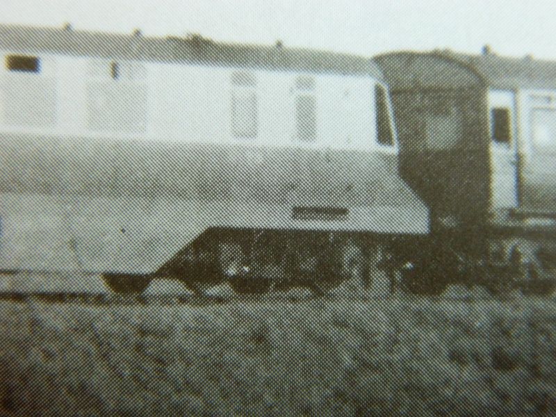
The photo is taken from Great Western Diesel Railcars, J.H. Russell, 1985, Copyright Wild Swan Publications Ltd. and J.H. Russell, and is used solely for purposes of research and education.
Save
©Nigel C. Phillips
Posted
Full Member
I did a bit more reading about the GWR diesel railcars in WW2 last night. Seems it's a bit of a black box - no records on what went on due to war-time emergency rules. And the paper records probably went when Swindon closed or BR threw them out when the cars were scrapped in the 1960's. Maybe the NRM has some information. So my theory as to why the GWR de-axled the later Swindon models (Swedish supply issues) is as good as anything else. Correction on my part - the gearing on the axles was the bevel type, allowing a simpler reverse gearbox arrangement.
What I do find striking is that the only reference I have found to the removal of the axles is in the RCTS book from 1952. Jim Russell in his book makes no mention, but all the photographs I have found show that from late 1942 they ran with one driven axle per bogie.
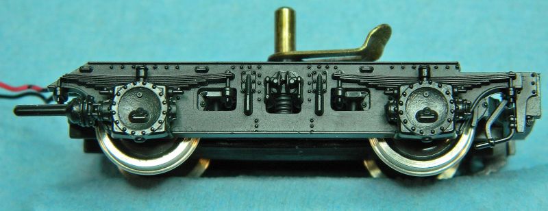
The fix is easy enough - lever the assembly off, 2 cuts and it's done. Fix back on with CA (most solvent glues don't work with the plastic Lima used, it might be different for recent Hornby offerings). This is almost certainly how all the Swindon-built cars ran from late 1942 on (including the 2 twin-sets). So unless you're modeling 1940-1942 or you don't worry about this level of detail (there are quite a few other issues with this model) this is what it should look like. As I said before, it's a pretty good representation of the prototype bogie considering its age.
The restored #22 at Didcot runs with one driven axle. It also looks like single axle driven bogies were found on some of the earlier diesel railcars in the 1950's as well. Cosmetically restored #4 at Swindon has one driven axle. #7 in 1955 was also running with one driven axle. As far as I can see from the online photos from #3 was also modified in the 1950's. Failed bearings and lack of spares? Hope Dapol have got this right with what they are producing. If anybody has any further information on the prototypes or models please let me (and YMRC) know. It's one of those DITD items.
Nigel
Edit 1. Found a comment in RMWeb by DavidCBroad in 2014 regarding "one axle per bogie running which would have limited pulling capacity." Post WW2 they were doing what they did best, branch line runs at 40 mph with passengers. Glad somebody else has noticed.
Edit 2. More photographic evidence at britishrailwayphotographs.com : #s 6, 7 (probable?), 8, 19 (1944), 20, 21, 22 (already noted), 24, 28, 29, 31, 34, 33/38 (twin set). Some of the early ones kept their shafts until scrapped: #s 13, 14, 17.
Edit 3. 7 is now definite in 1950 with a regular axle box replacing the gear box, http://www.warwickshirerailways.com/gwr/gwrms2537.htm
Edit 4. Found photo's of #s 18 (Pinterest) and 23 without cardan shafts between the driving axles.
Edit 5. #4, NRM.Regular axle box replacing the gear box.SaveSave
©Nigel C. Phillips
Posted
Full Member
'Nuff of the bogies, on with the wiring.
Next stage is prepping the body for the wiring and the speaker. Wires have to go in, sound has to come out somewhere.
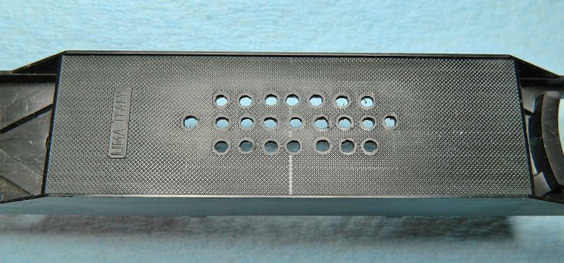
The speaker is going in the well where the weight was, intent is to have the holes in the bottom where the engines and exhaust would have been in the prototype, with the speaker facing down.
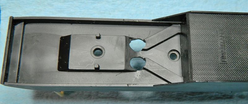
Two holes above the bogie well for the non-driving bogie wires. The wires will then go in the 2 channels that Lima conveniently molding in (see left and right side of the last photo). I made the holes big enough to allow for lateral movement and no rubbing.
And that's the speaker in position testing for fit. I'll be using lead sheeting along the sides and either end of the speaker for some weight (and sound absorption). The decoder is an ESU Loksound V4, so I'm using an 8 ohm speaker with enclosure (biggest one I have). I have a spare bass-reflex speaker somewhere in the spares box, I may wire both of them in.

Now the butchery to the body chassis is done (well, not quite, but the rest is minor) it's on with the actual wiring.
Nigel
Save
©Nigel C. Phillips
Posted
Full Member
Did the basic DCC wiring today Pictures below with some details.
Chassis with all the basic DCC wiring in place.
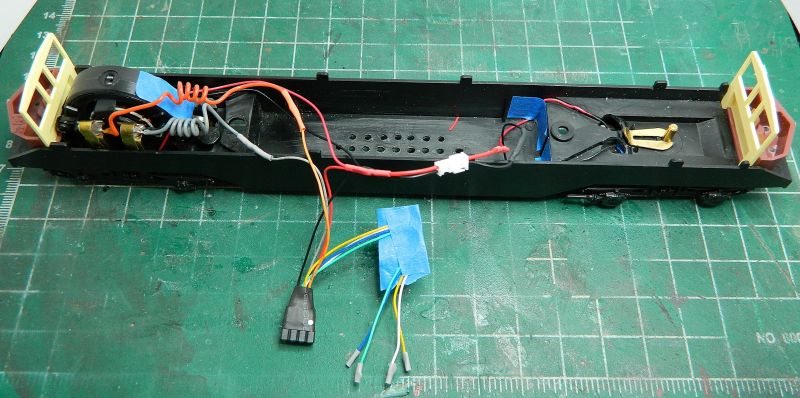
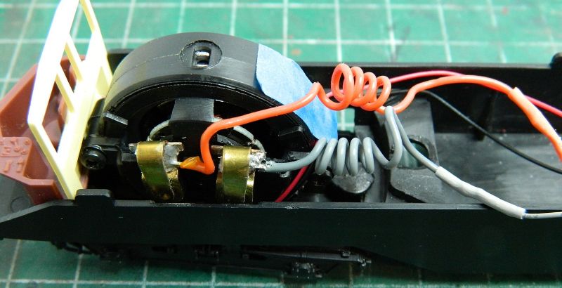
I beefed up the connections to the motor brushes, and put some springing into the wires to allow minimal stress on the solder joints during rotation.
The 8-socket wiring harness (Bachmann) is now wired in. The wires for the lights are protected at the ends with a bit of heat-shrink for the moment. Avoids costly shorts. Using a wiring harness allows a blank plug to be used for testing connectivity with DC, testing DCC with a cheap, non-sound decoder, and for swapping out decoders when necessary. None of which are possible if the decoder is hard-wired in.
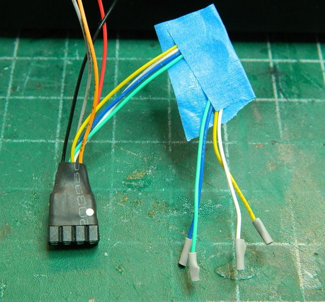
Hard-wired connector between the non-powered bogie and the DCC wiring harness. This allows the front driving bogie or the non-powered bogie to be removed for attention without performing contortions with the wiring. Also keeps the wires short. These are push-snap 2-wire JST-type connectors rated at 2A (and used for charging lithium batteries at way past this capacity). I'll be using these for the lights and the speaker. Plug and play approach.

Non-powered bogie wiring. There is enough slack in the wiring for full movement of the bogie. The wires are attached to the top of the bogie, no strain on the soldered joint to the wipers.

Next up - speaker wiring and some planning for the lighting circuit board (head and passenger). Centrally located LEDs/resistors and fiber-optics to the head lights I think, as space is pretty tight in the driving cabs for dedicated LEDs (unless I use surface mounted ones) and the capacity for butchery is limited.
Nigel
SaveSave
©Nigel C. Phillips
1 guest and 0 members have just viewed this.