Copper-clad sleepers/ties for hand-laid track
Posted

Inactive Member
Making the insulating gap
No. Right on 30, John.It might be the camera angle. The couplers lock right over. That's how I know that it's tight.
It's all good now. It just looks a bit ugly.
I've moved on.

Max
Port Elderley
Port Elderley

Posted

Full Member
Tried the pin hing method using track pins, which have a nice head already built in. Not necessary, as the point rails are sufficiently long and I have a floating hing at the closure rail end. Too fiddly for my pinkies.
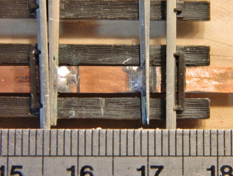
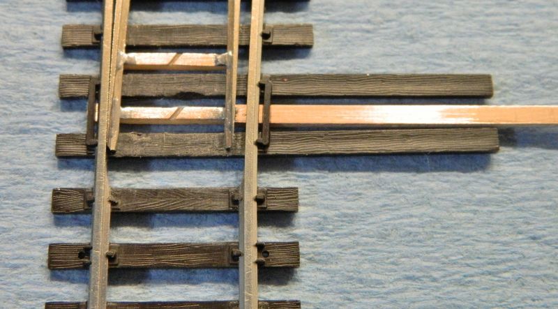
I swapped out the original wide tie bars, replaced with narrower ones (2.3mm wide from Fly By Night Industries) with a diagonal isolating cut. I reduced the gap from 2.4mm on this one to 1.5mm. Did the other 2, which had gaps of 2.6 and 2.8mm. Far East QC. All now at 1.5mm.
""hold on old mate," I hear you mutter, "what about the hole for the motor shaft?". Who said it has to be in the middle? More of that in a bit. I have a plan…
Pictures below, haven't cleaned them up yet. Looks a lot better with the narrower gap between the points and the stock rail.
Nigel
©Nigel C. Phillips
Posted

Full Member
The hole doesn't have to be in the center, I've used the Circuitron off set turnout actuators (wire in tube essentially) when I put a turnout too near a brace.
I didn't like to say about the state of the solder, I will await developments.
John
John
Posted
Full Member
I'm sure you've done this in the past, although I'm following a "how to" I found on the web by Bill Ataras from 1994 and one on using narrow copper-clad as tie bars in S-scale that goes into this in a lot of detail, and deals with how to not have holes in the bars. The aim eventually is to ballast the copper-clad and have cosmetic tie bars (2 of them) on top. I'm considering going to N-scale copper-clad ties which are 1.4mm wide to reduce the visual impact even more.
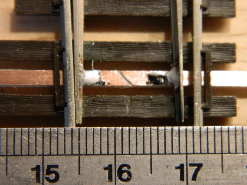
Solder? - it's the light and the angle and I took a photo immediately after I did the swap. Quick clean with-up with #400 paper and cream cleanser and it's fine. Lead-free cadmium-containing solder definitely does not flow as well as regular lead-containing solder unless I go from 25W to around 35W, and needs polishing to give a shiny appearance. Looks like a big blob from above, end on it's not. Something I need to keep in mind is that brushing with an abrasive cream goes through exposed copper-clad core like a hot knife through butter. Looks like I doubled the depth. Definitely an insulating cut. Needs a dab of epoxy in there.
Note I allow a bit of solder to go onto the foot of the rail (this is flat-bottom rail, not Bullhead) and through to the other side of the rail (limit is delineated by a 2B pencil line). I allow for this by a bit of extra metal removal from the foot of the stock rail. I also do not touch the head of the rail, with appropriate filing of the blade it's not necessary to remove any metal. Might be worthwhile tinning the copper-clad if a really neat appearance is desired. I shall investigate.
Nigel

SaveSaveSave
©Nigel C. Phillips
Posted
Full Member
Hi Max,Here we go . . .
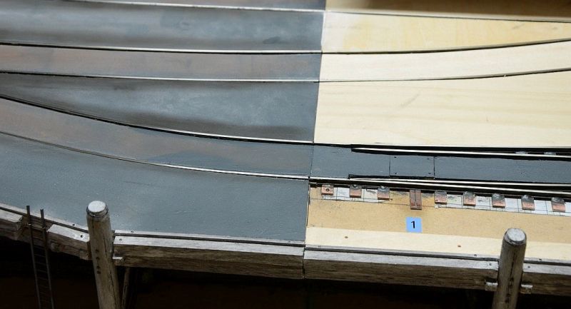
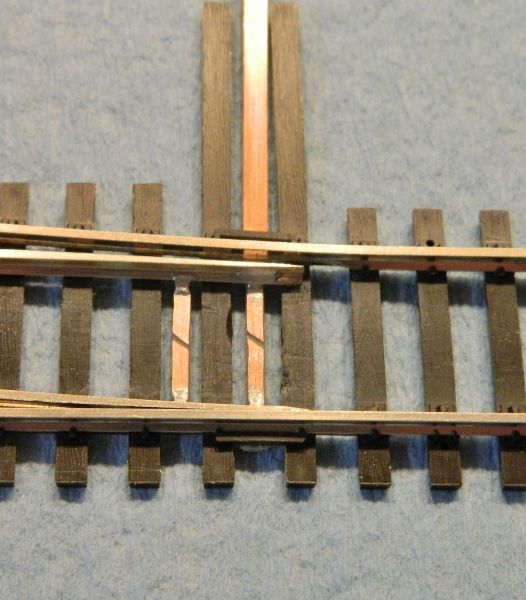
You can see the tight curve leading into the gauntlet on the left.
Allowance for the foot of the far point rail has caused the large gap on the infill. Once the outer filler pieces are installed, it shouldn't look too bad.
I just re-noticed the crappy soldering. I must fix that. :oops:
It helps to have a length of straight track greater than the length of the truck wheelbase leading in to the heel of the turnout. If not the leading wheels of the truck are at a different angle to the rear wheels and will bind. Increasing the gauge slightly on the adjacent curve will overcome this, as will having more lateral movement on the axles.
Nigel
Save
©Nigel C. Phillips
Posted
Full Member
John
John
Posted
Full Member
Thanks. Just ordered some of the narrower N-scale copper-clad, so It will change yet again.
Nigel
©Nigel C. Phillips
Posted
Full Member
John
John
Posted
Inactive Member
We had an operating session for about an hour yesterday. No problems, so I think I've gotten away with it. :cool:
There's nothing like having friends around to find out how it really works - or not!
Max
Port Elderley
Port Elderley
Posted
Full Member
Hi John,Y'know there's a saying "There comes a point when you have to kill the Engineers and get on wi't job". :cool wink
John
T' engineers wor fired eur long tahhm agoa. Wingit 'n 'is pal Bodgit run it naw. Summa' thee doa afta t' pub closes
This is fun stuff, engineering has little to do with it. I'd be using Proto87 parts if I wanted something approaching realism. Which I intend to do, but not on this particular project as they are only made for code 70 and 83 (tie plates, spikes, frogs, tie bars, point blades……). I canceled the order on the N-scale ties, just not cost effective when I only need maybe 2 pieces (12" long) and a pack of 10 is nearly $12 with postage. Out with the big file and some low tech hackery on the Fly-By-Night ones I have which failed QC for being too narrow. Tie bars rather than rods are quite common in North America, and are robust affairs.
Nigel
Save
©Nigel C. Phillips
Posted
Full Member
John
John
Posted
Full Member
I'll get Wingit and 'is pal Bodgit to knock something up using bars.
I've got them down to 1.7mm width from 2.4mm nominal, N-scale ties are 1.4mm. I will need a jig to go narrower, but I recon 1.5 mm will look OK.
Nigel
©Nigel C. Phillips
Posted
Full Member
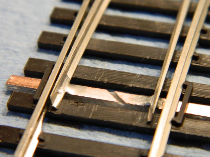
So this is what they look now after a bit of filing and fettling:
Final job will be some cosmetic bars and wivets in styrene.
Nigel
Save
©Nigel C. Phillips
1 guest and 0 members have just viewed this.