Shinohara Code 100 Turnout DCC conversion
Posted

Inactive Member
Power routing to DCC friendly track
I've got an idea that mine were Code 83? Can't be sure - it's all a blur.
Max
Port Elderley
Port Elderley

Posted

Full Member
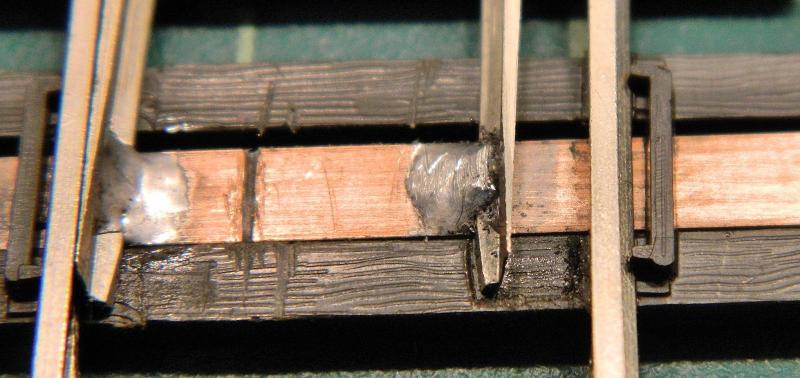
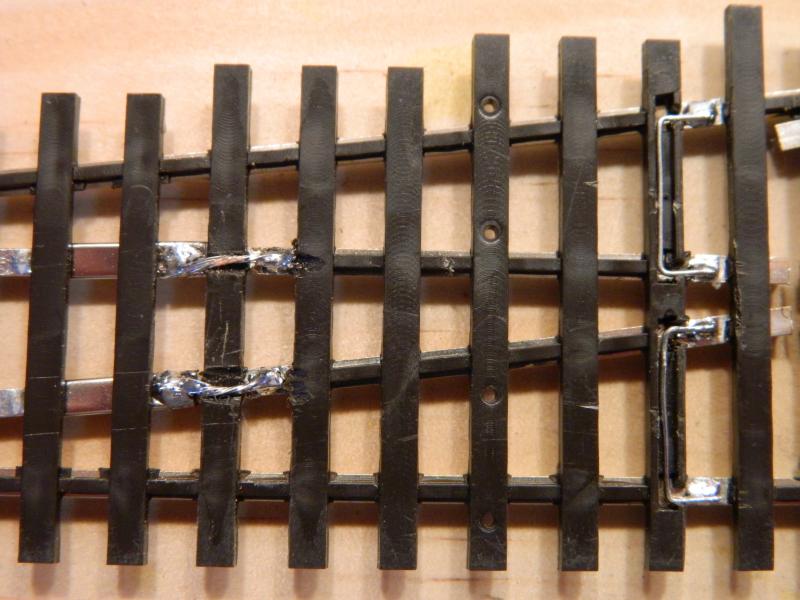
I made a start on the more up-to-date #6 turnouts this morning. I used 4mm copper-clad from C+L Finescale as the throw bar, it fits quite snugly between the retaining ties. There is a reason for this. I normally ballast the top of the tie-bar between the rails and outside of the stock rails, and will be adding 2 cosmetic round tie bars between the blades after ballasting and painting.
The copper-clad was given a very light wipe with #800 sandpaper, followed by a degrease with 91% IPA, and was held in place with masking tape on the bottom. I marked the outside position of the switch blades (the stock rail contact side) with a graphite pencil to stop solder from wicking through. The Shinohara metal connector was then desoldered, and the inside web and bottom the rails was cleaned as above. I soldered up keeping each blade next to its stock rail using 145° solder (Carr's) and organic flux. An insulating groove in the copper-clad was made with a small triangular file. This was checked with a multi-meter to make sure the sides were isolated. I also made sure that a bogie with pizza-cutter rims rolled through without bouncing on the bead of solder. The keen-eyed will note that the RH solder blob needed a smidgen taken off the top.
Completed tie bar.

Close up showing graphite barrier (light grey strip) on the outside of the RHS blade, and insulating gap on the LHS in from the rail. This leaves the center free for a hole if I decide to use stall motors in the future (which will mean another isolating cut on the RHS). Might as well do that tomorrow. The current plan is to use manual throw-switches with inbuilt frog polarity switching (Caboose Industries).
These later turnouts are DCC ready in that there are grooves in the underside of the ties/sleepers for wiring (closure rails and frog exit rails). I cut gaps for the wires, which will be bent to an [-shape, tinned and soldered to the underside of the rails between the ties/sleepers (shown in last photo). My smallest soldering iron tip is way too big for those tiny rectangular gaps, and if I cut the webbing i can move the ties/sleepers at risk out of the way. One tip I've come across is to cover the ties with wet kitchen towel to keep heat exposure down. Not sure about that, I'll experiment tomorrow on some old rail.
The Shinohara code 100 3-rail bridge track arrived this afternoon, very new stock, immediately stripped down to the rails and ties/sleepers. Exact match for the old rail. I'll make a start on the blades for the older #6's tomorrow, and hopefully get everything wired up.
NIgelSave
©Nigel C. Phillips
Posted

Full Member
The gap should be filled, it remains quite noticeable even after painting.
Ain't I just full of great wisdom? Or just a smarta*se.
John
John
Posted
Full Member
Hi Max,I've got an idea that mine were Code 83? Can't be sure - it's all a blur.
Could be, Shinohara do code 70, 83 and still do code 100. Code 83 is now sold exclusively by Walthers as their own brand. Production in Japan is in batches, so it's either feast (lotsa stock) or famine (back-order) regarding new stock availability. Next shipment is due in the shops October/November. New stock is decidedly more DCC friendly than the old. Walters Code 83 is sold as DCC friendly with isolated frogs and jumper wires installed. Their code 83 #6 double crossover is only $99.99. :roll:Isolated frogs and jumper wires to make it DCC friendly. I can do that for nothing on my $20 code 100.
Their HO/narrow gauge dual track is a real temptation to get back into narrow gauge. Cheaper than Tillig and a lot better looking.
Nigel
Save
©Nigel C. Phillips
Posted
Full Member
You've raised a good point. It's piqued my interest.
I've come across the grinding method and have given it a try a few times. Could be me, but there is often delamination of the copper from the base material with the Dremel and a grinding disc. It generates too much heat, and has an effect on the base. It gets hot enough to melt it, which is around 180°C if it's one of those polyimide base compositions, and the copper laminate detaches or reseals improperly. We've all had this happen with a too-hot soldering iron or repeated soldering*. I know the idea is to remove just the copper and leave the base intact, but doing this by hand with a Dremel and grinder disc is going to be hit and miss unless a jig is used to control the depth of cut.
In the past I've always filled that gap with epoxy to get rid of the groove. Remember I said I would normally ballast the top of the tie? I can see where a lot of vertical stress is going to cause a fracture, but most of the stress is lateral compression/expansion. I'm not that convinced that a groove cut through less than 5% of the thickness is going to lead to catastrophic failure. Half-way through I would concur. I know that with a groove this deep I have difficulty snapping the copper-clad with my hands, and that's about 50-60lb of force.
Like a lot of things in this hobby there is often a lot of hearsay and not enough hard data. In this case position of cut, depth, and vertical force required to fracture. Do you know if Norm Solomon really evaluated this or is this "his way"? Wright Track 10?
Which also begs the question, how much weakness is introduced by drilling a hole in the middle to accommodate a stall or solenoid motor wire? A 1mm diameter hole would be 25% of the width removed, even more if 3.5mm width copper-clad was used, leaving 1.5mm either side to take the stress. I would have thought this would be a lot more damaging than a light groove to one side.
I'll think about generating some hard data.
Nigel
*One of the reasons to solder first , cut the isolation groove afterwards.
©Nigel C. Phillips
Posted
Full Member
You are right I have the Right Track video which is where I saw Norm doing this stuff. BTW, it is worthwhile for everyone to watch because he does get into installing Peco track as well as showing how he does the handbuilt. He and Tony were tracklaying on Little Bytham.
Again, you're right, drilling a hole for the point motor pin also weakens the tiebar although perhaps not as much.
The tiebar does see relatively high stresses compared to the the static timbers.
On the other hand, if the tie bar does break it can be replaced in situ.
John
John
Posted
Full Member
In the interests of objectivity I did do a few comparisons this morning of grinding versus a triangular file cut.
C+L Finescale 4mm copper-clad (copper on both sides).
Markway 3.5mm coper-clad (one side only, old material).
Dremel at the lowest speed (5-8,000 rpm) with a 3/8" diameter/1/8 inch grinding wheel (the green one, fine stone).
Triangular file (fine cut).
A source of force - my hands, so this is subjective. Needs a proper lab with calibrated equipment to measure the shear force properly. I'll see if the local community college would be interested.
So, what did I find?
1. It's easier to control the depth of cut with a file than it is with the Dremel. Both would benefit from a jig if doing a lot of work.
2. There is definite copper delamination around the edges of the grind area using the grinding wheel. None with the file.
3. With double sided copper-clad resistance to snapping appeared to be slightly better with filing than with grinding. (I did 10 of each, alternating between the 2 methods).
4. Single sided copper-clad snapped very easily with both methods. Again, resistance was slightly better with filing than with grinding. This was old material, and the composition of copper-clad substrate has improved dramatically over the last 5 years.
5. Cutting a deep groove in the copper-clad (50% of the thickness) made for a nice snap-line and very little resistance. As expected, it's how we snap copper-clad strip (that or the Xuron cutter).
Conclusions:
1. This is another one of those old-wives tales. If the file cut is made just through the copper-clad it's stable. Go deep and it becomes susceptible to shear force. This is where the contention that cutting through the copper-clad with a file leads to instability comes from.
2. It takes very little practice to get a cut just through the copper with a file. Make a jig to get it reproducible. The action of the grinding stone affected the stability of the substrate just as much as putting a small cut with a file.
3. Double sided copper-clad is probably more stable than single sided (although that would need a head-to-head with new stock of the same width to confirm).
4. Use new material, not old stock. The core polymers have improved dramatically over the past few years, and are now more heat and stress resistant.
5. If a gradual transition from copper to core is desired for cosmetic purposes, use emery paper and feather in the gap. Otherwise fill in with 2-part epoxy.
6. Put the gap as far as possible to one side of the tie, and as far away as possible from the hole if using switch motors.
I'll stick with the file, as far as I can determine the structural integrity is as good-as or perhaps even better than when using the grinder. Safest way would be to use etched copper-clad ties/sleepers. DIY or DCC Concepts (their kits include tie bars). No good for me at the moment as they are OO UK outline. I might get an etching kit and do a few of my own for HO and EM. It's what copper-clad was designed for.
Some photo's below.
Nigel
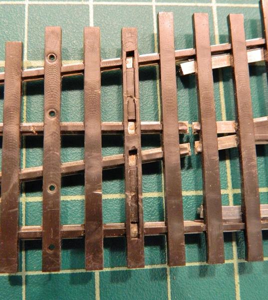
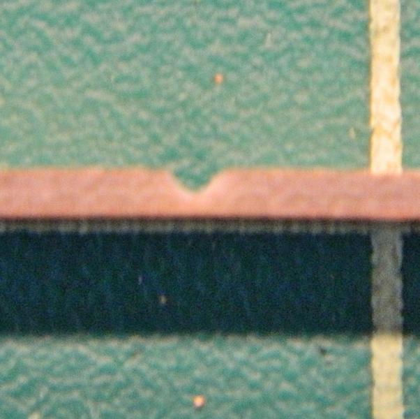
1. File. Through the copper-clad and less than around 10% of the core.
2. Grinding wheel. Even using the wheel some 10% of the core is removed.The top LH edge shows some delamination.
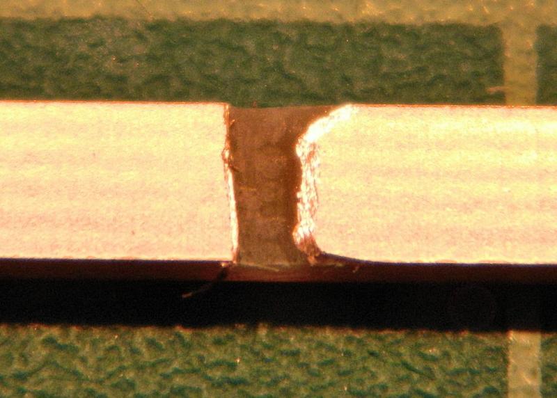
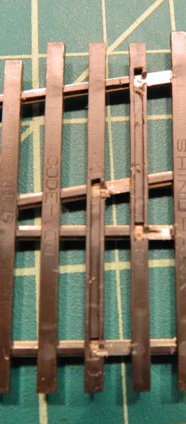
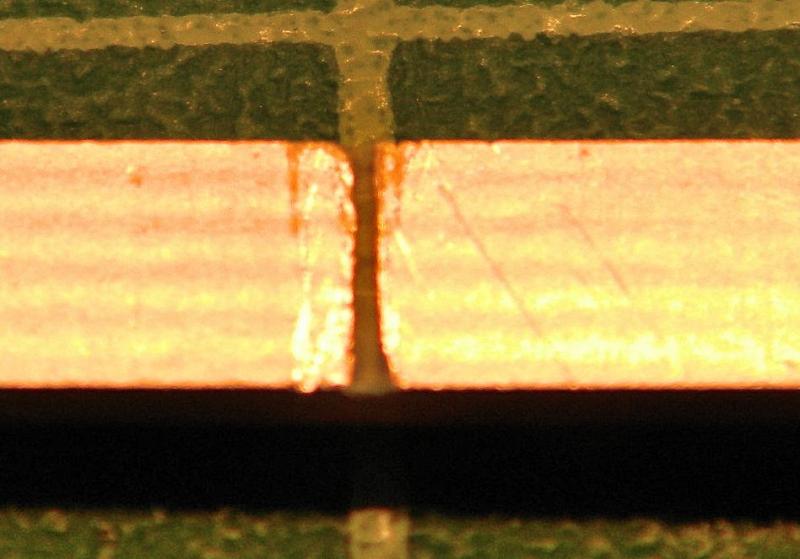
3. Depth of cut with file - good. Just through the copper-clad. (It's that tiny white valley on the upper edge).
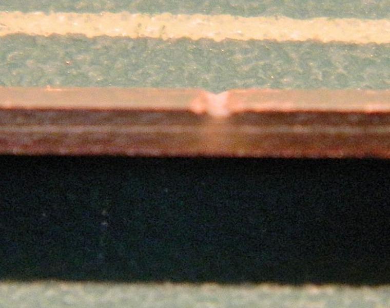
4. Depth of cut with file, 50% thickness - bad. This will give problems as it snaps easily.
Save
©Nigel C. Phillips
Posted
Full Member
I agree that it is difficult to control the depth of "scrape" with the cutting wheel, probably takes practice. You also need to watch that there are no shards of copper left.
Other than that, it is a personal choice as is so often the case. We all do things that are in our comfort zone. It's only modelling after all.
John
John
Posted
Full Member
Write a paper? No way, stopped all of that nonsense when I retired and filed my CV away for good. Never been happier. Mind you, if I get a positive response from the local community college that could change (or if I rig up a test jig to calculate stress).
As you say, we all go with what we're comfortable with. It really doesn't matter diddly whether it's a file cut or a grinding wheel. It's common sense that a deep channel one third or half-way through the copper-clad will lead to failure sooner or later.
What I have done with the next 3 turnouts is to cut the isolating gaps before I solder the rails up. The Shinohara Code 100 rail I got really ties in nicely with the existing rails, no jogs or steps , and the Shinohara rail couplers slide on a treat. It's a pain to shape the curved rail though. I'll be glad when I move onto the Code 70 turnouts. Hold on though a minute, I'll need some Shinohara Code 70 track…
Nigel
©Nigel C. Phillips
Posted
Full Member
I think I've watched that one. The look on Tony Wight's face when Norm Solomon dumped a shovelful of ballast mixed up PVA from a large bucket on the track and then proceeded to spread it around like an apprentice brickie on a Monday morning was priceless. As Tony Wright said "Well..there you have it".Well you're only supposed to scrape it lightly which shouldn't generate much heat. Epoxy fill might mitigate the weakening effect of the notch.
You are right I have the Right Track video which is where I saw Norm doing this stuff. BTW, it is worthwhile for everyone to watch because he does get into installing Peco track as well as showing how he does the handbuilt. He and Tony were tracklaying on Little Bytham.
Again, you're right, drilling a hole for the point motor pin also weakens the tiebar although perhaps not as much.
The tiebar does see relatively high stresses compared to the the static timbers.
On the other hand, if the tie bar does break it can be replaced in situ.
John
Nigel
©Nigel C. Phillips
Posted
Full Member
John
John
Posted
Full Member
Completed the wiring this morning on the newer turnouts The older ones will need grooves cutting in the back of the ties for the wiring using the Dremel at the slowest speed and very gingerly, it doesn't cut so much as melt plastic using a cut-off disc, but it's a lot faster than hacking away with a file. I'll compare with the diamond-coated cutter on some scrap ties and see how that works.
I used 24 gauge tinned wire for all but the switch blade connections. I checked a Peco code 83 I have, the gauge there is 26, so I should be OK re power draw (24 gauge is rated at around 3.5 amp, so unless somebody decides to start an old open-frame clunker on the turnout I should be OK). I used 20 gauge 7 strand wire (3.5 amp capacity) stripped and twisted up for the connection between the rail joiners that are soldered to the foot of the switch blades and pivot on the closure rails. This was to allow a bit of flexibility. I cut a groove in the webbing with the Dremel for the connection. There is just enough flexibility to allow movement of the points without any stress. I gave it a hundred switch movements just to make sure. Still good (although my hand is aching).
The connection to the frog is also 22 gauge and currently naked. This will run through a hole in the baseboard and will get some heat-shrink around it before installation (no naked wires under the board). This will be connected to the ground throw switch.
Apart from filling in the isolating gaps with a dab of 2-part epoxy (and some masking tape on the wheel rim side, which epoxy will not adhere to), and adding some dropper wires soldered to the foot of the stock rails that's it. I checked the continuity with the multi-meter, everything looks good.
Nigel
Photo 1. Exit rail wiring and frog wire.
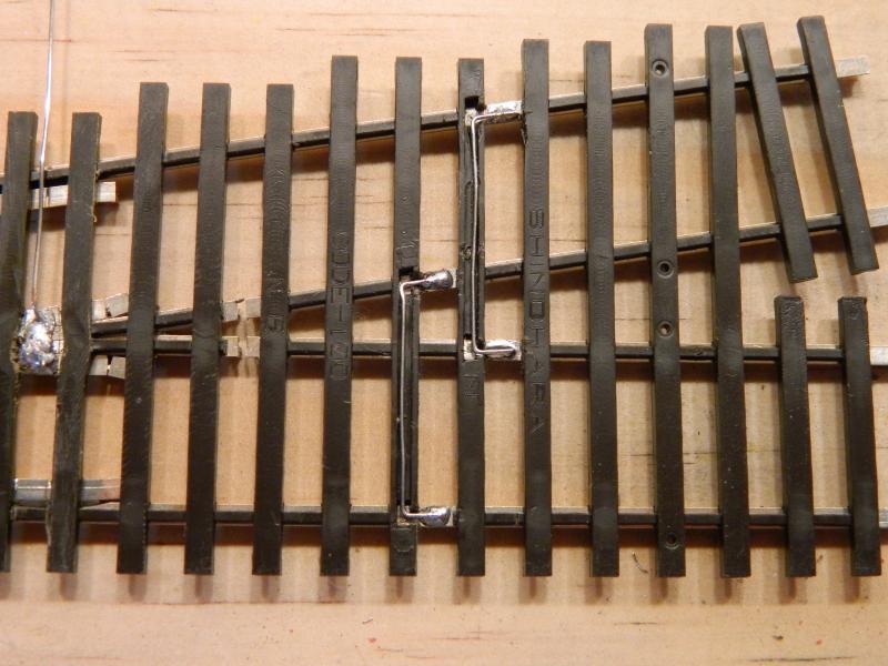
Photo 2. Closure rail to stock rail wiring. Lingered a bit too long with the iron at the frog.

Photo 3. Twisted wire connections between closure rails and switch blade rail joiners (which are soldered to the blades but not to the closure rails - pivot point is preserved).
SaveSaveSave
©Nigel C. Phillips
Posted
Full Member
John
John
Posted
Full Member
Thanks. Not quite commercial standards but it will do. I really must get an iron with a smaller tip for this sort of fiddly work.
Track feed according to the standard is 26-22 gauge, bus is 16-12 gauge. Anderson PowerPoles, which I like, bullet-proof.
Nigel
©Nigel C. Phillips
Posted
Full Member
Last post on the conversions.
I wired up one of the older Shinohara turnouts this morning after making the switch blades. These are pure DC models, no grooves in the ties/sleepers for wiring, power routing design. I decided against the Dremel with either a cutting disc or a diamond wheel for cutting the grooves - both melted rather than cut the plastic when I did some tests. In the end I used a small round needle file and straight edge to cut a shallow groove, and then opened it up with the milled edge of a small rectangular file. The ends of the grooves were opened to the rails up with the round needle file. Took around 5 minutes per turnout. Not as pretty as molded-in slots, but it looks OK from the top (
).Following a post in the "Tips" thread I've been using damp kitchen towel to minimize damage to the ties from the iron when soldering. Works well, although paper 'Shop Towel" is a bit more robust, and avoids questions such as "Where has all my kitchen towel gone?". Three minor accidents in 5 conversions, both confined to the underside and no structural damage. I did get some spare ties just in case.
These turnouts are now 100% DCC compliant, and the conversions did not take long to do. Only thing left to do is some 2-part epoxy in the frog isolation gaps. They don't affect running, but rail will "creep" with continued use, and the epoxy will minimize this. I'll post separately on that.
Next job up - those Shinohara code 70 turnouts, all power-routing design. More of the same. Plus that Gant track.
Some photos below.
Nigel
Photo 1. The operating theater. Damp shop towel on the bottom, kitchen towel on the top. My wife's in Florida at the moment, no questions about this particular usage. The wedge shaped bit in the middle is the soldered bottom of the frog. The power wire is to the right, with a loop in the end to ensure more wire-solder contact than with a straight piece (twice as much).
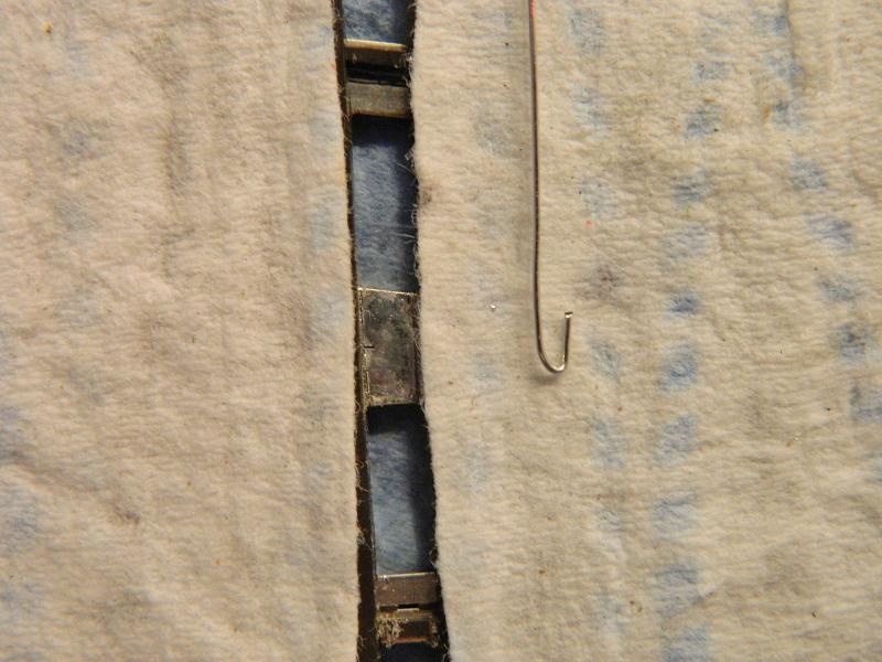
Photo 2. Wired exit tracks and frog.
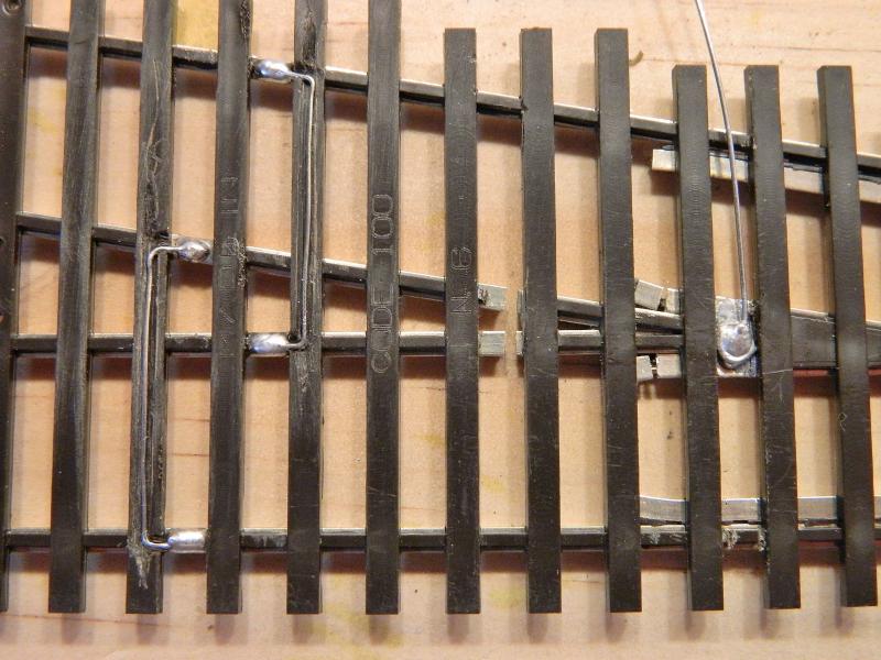
Photo 3. Closure rail and blade wiring. I've staggered the connections here to minimize the number of web cuts on each tie.
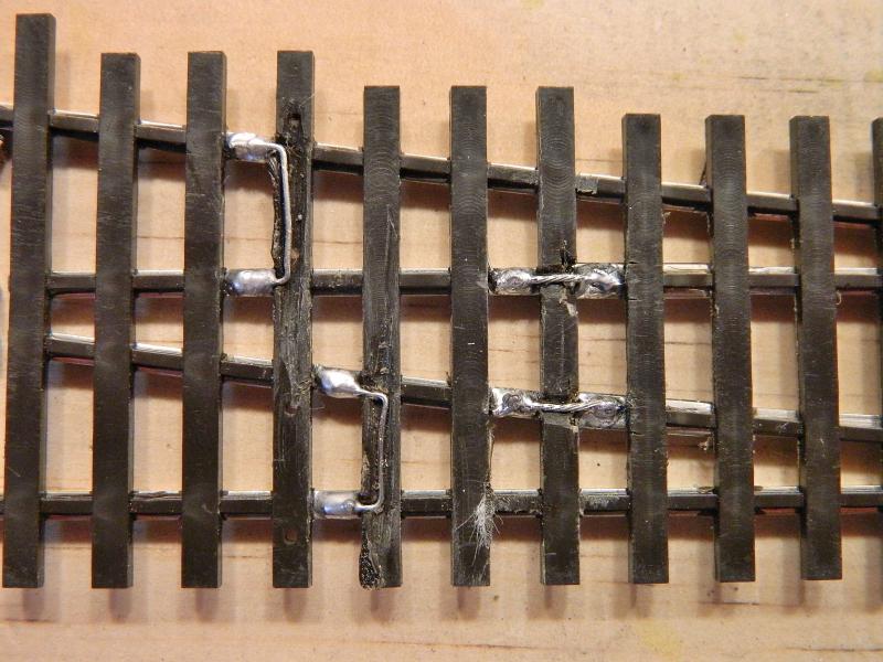
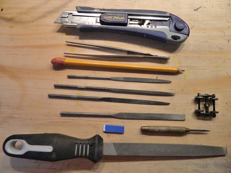
Photo 4. Tools of the trade (plus the 20-45 W iron, Carr's 145° solder, Kester 951 no-clean organic flux, sandpaper, and the multi-meter for checking continuity and isolation). And of course a nice solid piece of wood to work on. It ain't complicated. The blue thingy is my jig for setting the stock rail/point blade gap - 2 bits of styrene sheet with blue masking tape. The pencil is for shading areas where solder is not desired. The Kobalt cutter has heavy duty snap blades, and is a most useful piece of kit for trimming bits off the ties, as is the dart head for cleaning up and generally poking around to see what's going on. The big file is for initial metal removal from the points. The 4-wheel bogie is a Kadee sprung model - most unforgiving when it comes to iffy track, especially point blades and frogs.
SaveSaveSaveSave
©Nigel C. Phillips
Posted
Full Member
John
John
Posted
Full Member
Thanks, it was actually fun. Almost a production line. These old Shinohara turnouts are an extreme case of power routing and an interesting (for want of a better word) switch blade arrangement on the really old ones. Bit of work and they look as good as the latest "DCC Friendly" ones. For about a quarter of the cost. More money for other stuff.:doublethumb
The only down-side to all of this is I am now out of the cadmium-containing 145° solder. Next packet is the new beryllium-containing one, which is not that easy to work with (and just exchanges one toxicity for another). There is probably some of the old one lurking on eebuygum.
Yes, let's hope others are inspired to ditch those insulfrogs, and wire-up turnouts for proper DCC operation, all rails powered, with isolated live frogs. I must say this was more work time-wise than doing it from scratch, which I might have done if the module standards were code 83 track. Then again, the Peco ones look OK if a bit fragile (the rail has a tendency to pop from those very fine spikes).
Nigel
©Nigel C. Phillips
Posted
Full Member
Turnouts can be repaired with copper clad I reckon. In fact my first effort at hand built points was to deconstruct old Peco code 100 and use copper clad. This way I could change the radius. I still had to make the common crossing. Good fun.
John
John
Posted
Full Member
Carr's 145°. Health and Safety said cadmium vapor was not good (which it's not), so it was changed to bismuth instead (which is also not good, but for different reasons). OK as long as there is adequate airflow and a temperature controlled iron is used. An unregulated one can get interesting as the cadmium combines with oxygen at high temperatures. Any soldering needs adequate ventilation across the work and away from you, never towards you. Al fresco is good. As far as I know it doesn't mess with the ozone layer and the amounts released at proper soldering temperatures are minuscule.
The old Carr's 145° sticks nicely to the tip of the iron (I believe it has a wide temperature melt, the new one drips off as it has a short melt. Both do the same job. May behave better with a decent temperature controlled iron. I keep mine at around 25 W for detailing work, I have no idea what the actual temperature is.
Kester 951 organic flux seems to work well with Carr's solders and brass/nickel silver. Safe to work with a no mess.
Nigel
©Nigel C. Phillips
Posted
Full Member
I got some Tix flux from Hobby Junction which I like - so much so that I bought a second bottle.
Tix Flux - RioGrande
I like that it's non-corrosive although I do find it still gets up my nose.
Dave also pressed me into getting some Tix solder which I tried and hated. I'm guessing it's lead free. I've also got a small bottle of a solution that stops parts from being soldered - tried it yesterday when soldering a nut to brass - works well.
I generally set my iron to 350C for 145 solder. If I have a large surface area I'll crank that to 380C. I use 300C for low melt, 70 solder - haven't melted anything so far.
John
John
1 guest and 0 members have just viewed this.