Shinohara Code 100 Turnout DCC conversion
Posted
#219885
(In Topic #11980)

Full Member
Power routing to DCC friendly track
I'm using code 100 track on my modular HO layout (that's the standard, ostensibly to accommodate pizza-cutter wheels and accompanying tread widths of old dinosaurs with wheels and motors). Code 100 corresponds to about 150lb rail, suitable for main line freight running, so it's reasonably prototypical. The standard allows code 70 for branch line work, more to my liking, and no dinosaurs allowed. It's been a few years since I used code 100 track, so after some reviewing (armchair and real layouts) of the choices over here - Atlas, Peco, Micro Engineering, and Shinohara - I settled on Micro Engineering as their flexitrack is available with weathered track and ties (sleepers), and the ties are a lot thinner than those from Atlas and Peco (less ballast, less weight). It also stays put when bent. I have a gantlet bridge in the plans off the main lines, that one will be hand-built.The downside is Micro Engineering do not do code 100 turnouts. Atlas and Peco code 100 turnouts do not look good next to the Micro Engineering flexitrack (they stand out like sore thumbs actually). Shinohara code 100 points can be got as NOS with a wide range of frogs (#2-#8), and types (LH, RH, wyes, single and double cross-overs, slips), and their ties are a very good match to the Micro-Engineering ones. Downside is that they are decidedly DCC unfriendly (I'd go so far as being downright antagonistic). Many a brave soul has tackled making these turnouts DCC friendly, with some good and not so good conversions being posted on the usual sites. The tools required are basic - a Dremel with a cut-off blade (or a jeweler's coping saw will do), soldering iron, and track gauges. Game on!
An eebygum spending spree got the turnouts (all new old stock, #6 frogs, 3 LH and 2 RH, average price $7.50 (about £5.75) and some Shinohara track connectors (pack of 50 for $8.00). These are essential, more on that as the post develops. The turnouts come in 2 types - the older ones which are the DCC antagonistic ones and require the most work, and the newer ones which are just DCC unfriendly. I am going to make a start on the DCC antagonistic ones (3, all LH), the other 2 are RH DCC unfriendly and will come afterwards.
So what's the problem with Shinohara turnouts? Power routing with a vengeance! First photo below shows a #6 LH turnout out of the box. The stock rails are fine, but that's about it. The frog is part of the power-routing, no gaps before or after, the closure rails are continuous with the frog and are way too short, the point rails are connected to each other (twice, once at the switch bar, once at the closure rails). I connected one of these turnouts to some track using insulating joiners at the frog rails, and newer stock with RP-25 wheel treads ran though fine on DC and DCC. However, wide-tread wheels or under-gauge wheelsets (a common problem, especially with metal-wheeled freight and passenger stock) will make sparks fly with DC and short-out DCC.

The figure below shows why these turnouts cannot be used for DCC without modification. Any contact of the wheels on the red stock rail with the black point rail will cause a short. This normally happens at the stock rail-closure rail junction. OK with those old pizza cutter wheels, open frame motors and DC power, just adds to the excitement with a momentary jerk. For DCC power it's a short and some interesting comments and looks from your fellow modelers as the block shuts down momentarily. This is probably why Shinohara used such short point rails to keep this problem to a minimum. Switch the points and it's the same problem in reverse. Electrical continuity depends on a good contact between the point ends and the stock rails, as well as between the closure rails and point rails, the latter of which is a sliding contact under the rail foot. Both of which are a definite no-no for DCC operation.

That's the background, design changes in the next post, then on to cutting, soldering and rewiring.
Nigel
SaveSave
©Nigel C. Phillips

Posted

Full Member
Atlas turnouts from what I've seen are execrable - unless they've changed their tune over the years.
I quite like the look of Peco code 83, but, despite being designed for NA track, doesn't seem very common. Most NA layouts that I've seen (not all that many to be sure) tend to use Peco code 100 with Atlas plain track.
Code 100 is so yesterday. I recall a discussion that we had at the club as to whether the new layout should be code 100 or 75. Code 100 was decided upon because some members thought they might have "dinosaur" stock. In the event, no-one's stock was so old that it wouldn't happily traverse code 75 track. The branchline, you will recall, was code 75, with hand built turnouts.
I suppose the Shinohara that you've pictured will look OK when painted but the heel looks clumsy.
The common crossing can be isolated by cutting the rail just before it and wiring for DCC. Doesn't seem too difficult to me - unless I'm missing something.
Did you consider making your own turnouts?
John
John
Posted
Full Member
In reverse order:
Yes I did consider making my own using code 100 rail, decent prototypical frogs can be had from Proto87 (code 83 would be the closest), along with a raft of detail items (scale spikes, plates, fishplates, tie rods). Too many other jobs on the todoit list, and I've only just started modeling again after an enforced break of 3 months. There is one small section with a gant track over a bridge in the plans, rather than modify existing turnouts it's easier to scratch build.
Wiring for DCC is straightforward.
The heel (of the frog) is poor (non-existent in fact). The turnouts would benefit from the addition of Proto87 frogs except I can't get them in Code 100, so filling with low temperature solder or even metal epoxy filler from the hardware store followed by a bit of judicious filing and sculpting may be called for.
Code 100 is still the NMRA standard, and the club follows the standard. I hate to think what would happen if I turned up with code 83 (which I like, although Peco's efforts are very fragile, the spikes are not robust and the rail will pop out if looked at) or (gasp) code 70 (which I prefer) on the modules. Using code 100 does give some leeway for bad ballasting (i.e. up the insides of the rail). We do have a couple of dinosaurs that get brought out at meetings. Ancient coffee grinder brass heirlooms that cannot have the wheels touched. Probably because re-wheeling would be a small fortune even if the wheels were available (quadruple Ultrascale prices at least for a 4-6-2). Oh well, it's only a hobby.
Peco code 100 HO/OO (which is neither fish nor fowl) and Atlas Code 100 still get used a lot. Atlas is a bit too springy for me. Micro Engineering, even in code 100, is the bees knees as far as I am concerned, although difficult to conform to tight radii. The ties/sleepers are not as thick as Peco or Atlas, so a bit of height adjustment is required whenever Micro Engineering meets them.
The sleepers/ties on the Shinohara turnouts are almost the same as those on Micro Engineering flextrack, and that was the deciding factor as I do like uniformity when possible. Peco/Atlas code 100 turnouts just look out of place with Micro Engineering track.
Nigel
©Nigel C. Phillips
Posted
Full Member
Good news - I was reading my first issue of 0 Gauge Gazette today. There's an article about how railway modellers may be less prone to dementia than others. The author puts it down to the requirement to be physically dexterous and the need for intense concentration.
Anyway, it sounds like you have your pointwork in hand so I will watch with interest …. and stick my oar in when the mood takes me.
John
John
Posted
Full Member
Oars to rowlocks it is then (or in this case, blade to plastic and iron to solder).
Nigel
©Nigel C. Phillips
Posted
Full Member
The diagram below shows the proposed changes to the Shinohara turnouts. Apart from the work necessary for DCC operation, I've added one more change so that the point blades match those on later models (which are longer).

1. Make frog isolation cuts and add power leads from stock rails to frog rails.
2. Infill frog heel infill with metal epoxy (thanks to John for pointing that one out). Wire frog for polarity changing.
3. Make frog isolation cuts
4. Add power leads from stock rails to closure rails.
5. Remove current switch blades and connector, make good sleeper/tie underneath. Make up longer switch blades and solder ends to new copper-clad sleeper/tie.
6. Remove current tie bar and replace with copper-clad sleeper/tie.
Step 5 may be problematic with what would still be short blades and stiff code 100 rail. Testing will tell. Later Shinohara models use rail connectors soldered to the blades and with a degree of lateral movement on the closure rails (their connectors have 4 fishhead bolts/nuts stamped in, a lot finer than Peco/Atlas/Micro Engineering rail connectors, JLTRT). If that approach is necessary some flexible power leads from the stock to rail blades will be necessary to ensure electrical continuity.
Off to the store to get some metal epoxy, then it's out with the Dremel.
Nigel
Save
©Nigel C. Phillips
Posted
Full Member
Code 100 flat bottom rail is pretty hefty so I doubt a (Tortoise) point motor will be able to move an unheeled rail. It does work with code 75 bullhead though - even code 75 FB.
There is a lot of material. When I've made code 100 blades, I start with a grinding wheel to get rid of most of the material, finishing with files. It's more a carving job and art than anything else. A file with a dead edge is useful to have for this. I have the EMGS jig for code 75BH but I'm not aware of one for code 100FB. You might want a rebate in the stock rail too.
For joining the rail to the tie bar, you can solder but fatigue will probably break the joint at some point. From Norman Solomon, I took away a neat dodge. Get some brass pins and drill the tie bar (non copper side up) in two places - where you want the inside of the blade to be. Insert and bend the pin and solder it to the blade web. It is easier said than done I admit, but perhaps worth a thought.
John
John
Posted
Full Member
Shinohara use ground blades, they're substantial bits of gear. Lot better than Peco pressed blades (which should be filled with solder to give them some meat).
Progress today: Isolation gaps cut, blades cut (longer to match the newer turnout) and filed, frog heels filled with 2-part epoxy containing metal filings from the blades, gaps cut in webbing for soldering wires. Shinohara use an interesting "floating blade" on their newer turnouts where the junction between the blade and the closure rails is a rail connector. This is soldered to the blade and is a loose fit on the closure rail. Works fine as long as the tie bar is a reasonably tight fit. I'm going to use droppers on the blades (soldered to the rail connector) to ensure power gets to them. Bit neater than a floating piece of copper-clad.
Next up will be tie bars, and wiring.
Pictures tell the story.
Nigel
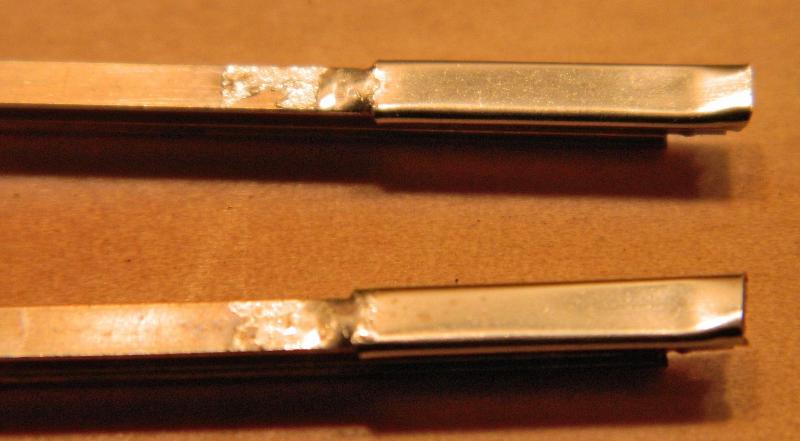
Photo 1. Isolating rail cuts made for the frog, heel of frog filled, closure rails shortened, and new, longer blades made. I'm doing a batch of 5 turnouts at the same time.
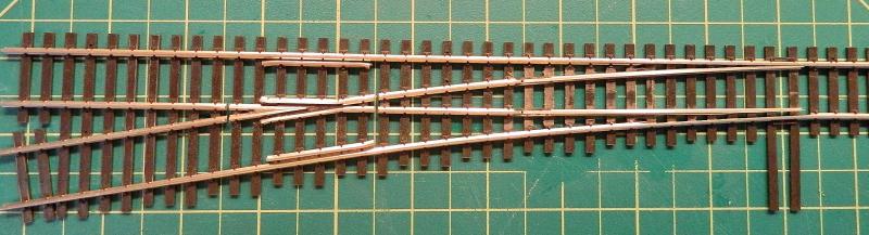
Photo 2. New blades with floating rail connectors to closure rails. The tie bar is meant to keep them in place.
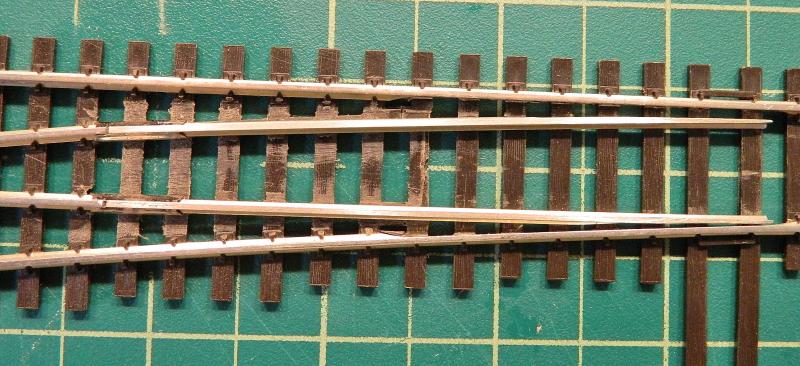
Frog heel filled with 2-part epoxy containing metal filings. This will be painted rust when laying the track. The rails need a polish with some 1000 emery paper.
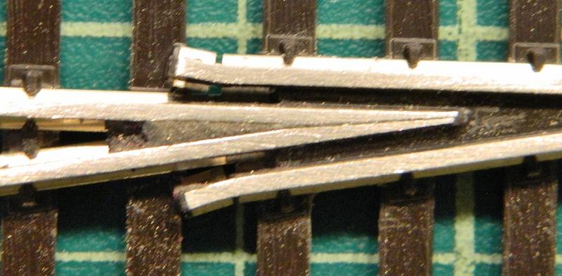
Underside of frog with a section of webbing removed to expose a nice convenient blob of solder just right for the polarity wire.

SaveSave
©Nigel C. Phillips
Posted
Full Member
When I had responsibility for wiring harnesses, conductive epoxy was used a lot. It contained silver particles. I recall that it was eyewateringly expensive - but then anything used for aircraft tends to be silly prices.
Now the turnout is starting to look more convincing and your mods will improve performance. Hope the lads in the club are suitably impressed.
John
John
Posted

Site staff
One of my local modelling mates has been converting the Shinohara Code 75 . Uses the tiebar metal but cut to electoral separate the blades and held to the tiebar with very small bolts and uses metal joiners for the blade hinge point like you are doing.
I will see if I can get him to send me photo or two.
Ron
NCE DCC ; 00 scale UK outline.
NCE DCC ; 00 scale UK outline.
Posted
Full Member
Thanks.
Not all Shinoharas are the same. The pictures below are the newer version, the latest versions in code 83 and code 70 are DCC compliant. I have 2 of these newer ones, not so much work as the 3 older ones. Something to watch out for when buying old stock - make sure it's the black box, not the red one.

First thing to note is that the connecting bar at the junction of the point blades is gone and the connection with the closure rails is now with a rail joiner. There is still the connecting bar at the points, so good old power-routing is still in force. Usual cuts around the frog, copper-clad tie bar and appropriate wiring will get them DCC compliant.
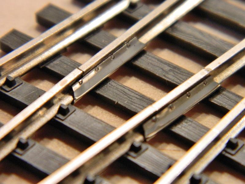
This a close-up of the rail joiners, being used here as a pivot for the point blades. Conductivity is of course questionable as it's a dirt-trap, the contact between the point blades and the stock rails is still the real connection. The plan is to attach some flexible wire droppers to the underside of the connector. Nice idea to have bolt head/nut impressions stamped in, saves on fishplates. I snagged a bag of 50 on eebuy gum for $8.99.
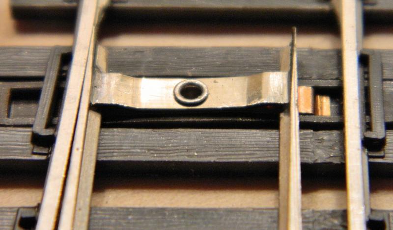
Shinohara's idea of a locking spring - a brass piece under the connecting bar that is supposed to latch under the foot of the rail. I simply ground off the rivet with the Dremel to free everything up.
Underside of the point rails. The rail connector is soldered on. Plenty of room for a connecting wire.

And finally the topside of the rail joiners. The ends have been slightly flared to give about 0.5mm rotation around the ends of the closure rails, so putting the wire about half-way down under a tie will need around 1mm lateral movement (i.e., a 2mm diameter hole in the tie and track bed should be enough with stranded wire.
Nigel
SaveSaveSave
©Nigel C. Phillips
Posted
Full Member
This was a big bugbear of mine with Peco points. I had the hinge of one of my code 75 Peco points fail and had to solder the blade to the closure rail. The Tortoise had the muscle to move it though (0.032" steel wire).
John
John
Posted
Full Member
I had a (subjective) look at what it would take to move an unjointed, fixed switch blade in code 100. The Tortoise may be up for it, the plastic ties are not. Methinks a few (actually a lot) of copper-clads would be required to keep everything in place. Longer blades help of course, but it looks rather odd. Code 100 rail is a lot more rigid and resistant to lateral movement than code 70/75 rail (and a lot harder to bend to shape, I'd hate to do a #4 turnout, these #6's are bad enough). After this quick bit of investigation I'll be going for droppers from the rail joiners as planned. As you say, relying on switch blade contact with the stock rail is not good enough for DCC and the Shinohara rail joiner joint is not intended to conduct current (and will wick paint at the slightest opportunity).
I've come across methods using springs, soldered pins, soldered bolts on the rail in threaded copper-clad (drill and tap the copper-clad, insert cheese-head bolt, solder rail to bolt head), sliding contacts with copper-clad, the list is legion. A lot of this falls into the "just because it can be done doesn't mean it should be done" category. I think 2 vertical and flexible wires is actually the simplest and most robust, and gives the least mechanical resistance for the motor. Solid copper cored wire soldered to the rail connector and dropping vertically would also work as the rotational arc is very small. Connect to the power bus using flexible stranded wire.
Nigel
©Nigel C. Phillips
Posted
Full Member
I'll be building C&L code 75 BH turnouts for my layout (whenever that happens :roll:) so your experience with the tiebar might help.
John
John
Posted
Full Member
Code 100 is tough to bend, you're right, no finesse required. I've been using Atlas code 100 for the new switch blades, and have had some nagging doubts about it. The profile is not exactly the same as Shinohara code 100, the head is slightly wider and taller and presents a distinct step where the 2 meet. Getting Shinohara flex track just for the rails means buying a pack of 10 (a $75 ouch) as nobody seems to have single pieces available. So I ordered a piece of bridge track from my favorite hobby shop for $6, which has a guard rail as well as the stock rails (3 x 20" pieces of rail, which would be almost the same as 1 piece of flex track). Should be enough there for the blades (3 turnouts). Should arrive Tuesday or Wednesday so I'm taking a break until it gets here.
Luckily Shinohara code 75 flexitrack is readily available for the turnouts that I will also need to convert (5 in total). Plus that double cross-over needs converting to DCC operation.
Nigel
©Nigel C. Phillips
Posted
Site staff
Nigel, you should should ask Max about the "fun" he had with the double crossover by Shinohara and DCC !Luckily Shinohara code 75 flexitrack is readily available for the turnouts that I will also need to convert (5 in total). Plus that double cross-over needs converting to DCC operation.
Nigel
But then he may reply himself as he reads all posts.
Ron
NCE DCC ; 00 scale UK outline.
NCE DCC ; 00 scale UK outline.
Posted

Inactive Member

I bought two Shitohara double crossovers for A$100 each.
Somewhere I have a photo of them after I cut them up with the tin snips.
They are complete rubbish.
Max
Port Elderley
Port Elderley
Posted
Full Member
Why am I not surprised. I was waiting for this one. Shinohara Code 10O track is not fine scale, but it's a lot closer (and I do mean a lot) than Atlas or Peco Code 100 track with their over-dimension ties/sleepers and non-prototypical spacing. Closest I've found is the track from Micro Engineering. I'm between the devil and the deep blue yonder here, NMRA still says Code 100 for modules, my club is 100% NMRA with a lot of grandfathering (and grandfathers), so code 100 it is. I'm using Micro Engineering flex track, which has scale ties/sleepers and a decent profile to the rail. Which then raises a bit of an issue, Atlas/Peco turnouts do not match Micro Engineering track (to me they look awful together, anybody who says they look fine after ballasting and weathering is being generous or maybe needs a visit to the optician), plus shimming is the order of the day because of the difference in tie/sleeper height. Micro Engineering do not do turnouts in Code 100. Shinohara turnout ties and rail match Micro Engineering, so it's a no-brainer what the combination of track needs to be.
Their turnout design is interesting. The original approach from what I've read was to get rid of gaps in the rail so that it looked more like the real thing. Which is only reasonable if it's power routed from tip to tail. As I've said previously, OK for DC, not so good for DCC. Shinohara's Code 100 turnouts are actually more robust than those from Atlas or Peco, and it's not a lot of work to get them DCC compliant.
Now onto those "rubbish" crossovers. I've got a Shinohara #6 double crossover in Code 70, which works fine as is with DC. Making it DCC compliant is just more cutting/wiring, and frog juicers will eliminate much of that (with or without power routing). The two frogs that look as if they're insulfrogs are not, There is a live section of track exposed with opposite polarity to the crossing rail, it's a potential short area. Easily addressed by fully isolating the frogs Mine is the intermediate one with the rail joiner connections between the closure rails and the point blades. The tie bar connection at the points needs removing and replacing with copper clad, more for appearance sake than anything else. It's one of those cases where power routing actually makes more sense than independent, live circuits. Given that frog juicers are now quite happy with power routing, it's a viable option with minimal changes. This is for the home layout, and I know my stock (including locomotives) is at the right gauge and there is plenty of space between the point blades and the stock rails for my semi-fine scale stock wheels. Not something I could guarantee with the modular club.
I've already been over the track with the meter to identify potential short areas (in addition to the obvious ones). These two highlighted in red are the worst (there are a couple more minor issues):
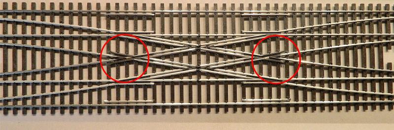
What look looks an insulfrog is far from it - there is a naked bit of rail in the middle.
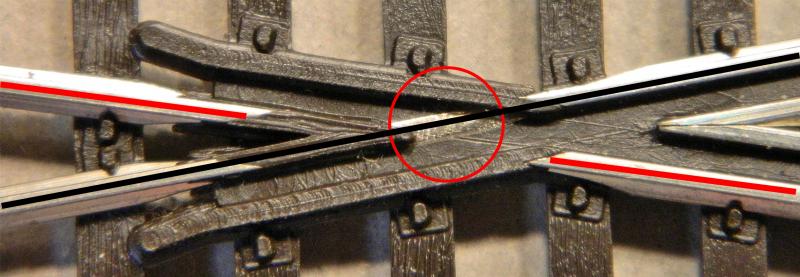
One of the "insulfrogs" magnified. The wheel on the red rail is supposed to ride over the black rail (opposite polarity) when crossing the frog. Hmm. Bit of use and some wear on the plastic frog tip or some pizza-cutter rims - sayonara! Isolating the 2 frogs by cutting the rails before and after and using a Frog Juicer with the as-is power routing would be the obvious way to go. Or simply grind the rail down and fill with epoxy, although the guard rail/stock rail opposite is also a problem area. This one cost me $20, current retail is around $60, an afternoons work and two single juicers for around $23 (which I'd need anyway), job done.
Now with a bit of careful snipping you can get 2 single cross-overs out of a double cross-over, but Shinohara do perfectly good left- and right-handed single cross-overs, so no contest there either.
Careful analysis shows these turnouts are not "rubbish" (very bad; worthless or useless), far from it. They're a good compromise between prototypic dimensions and robustness. One questionable design element (presumably for structural stability) in my book is no justification for binning it, especially when it's easily corrected. I'm almost tempted to get some code 70 frogs from Proto87.
Building a double cross-over from regular turnouts and a regular piece of cross-over is of course feasible, but at almost double the length. If I can get an old Shinohara double cross-over in code 100 at a reasonable price it's going in a club module. Useful piece of gear when it comes to switching trains from one track to the other. Double track here doesn't mean "up" and "down" lines. The direction often depended on gradients and traffic.
One man's meat…
Nigel
SaveSaveSaveSaveSaveSaveSaveSaveSave
©Nigel C. Phillips
Posted
Site staff
http://yourmodelrailway.net/view_topic.php?id=14142&forum_id=6#p256860
not for the faint hearted.
Ron
NCE DCC ; 00 scale UK outline.
NCE DCC ; 00 scale UK outline.
Posted
Full Member
I read it some time ago. If I want to preserve the geometry and the 2" track centers I'm looking at a 9.5° diamond crossing, and those are long (and far and few in Code 100). Plus I'm mixing Code 100 and Code 75. And it's Peco ties/sleepers (which I'm trying to avoid). Easier to go with a Shinohara, warts and all, and spend an afternoon fettling and grumbling. Project for the future.
Now if the NMRA decided to modify the HO module standard…
Nigel
©Nigel C. Phillips
1 guest and 0 members have just viewed this.