John Street - BR(E) - 1960
Posted

Full Member
My second bash at model railway-ing
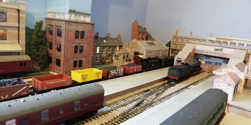
Well, that's the Terminus more-or-less completed.Over the past week or so I've been working on trying to get an uncoupling ramp to work. Time has been at a premium recently so not much progress has been made on it. At the moment it's in two parts - first part (the ramp) is only on a spare length of track and the second part is still in the "I'm still working on it" phase - but the idea, culled from a number of various ideas from across the model rail community, appears to work nicely - up to a point! In the process of this project I'm learning quite a lot about controlling servo motors.
One important point I wasn't aware of (and doesn't exactly get mentioned on the 'spec sheet') is the amount of current these little devices take - and I get the impression that I'm not alone in this respect. Given that these devices can be used in model aircraft, I expected they would be relatively low current devices and so I thought a 7805 (a 1amp device) power supply would be more than adequate to run a single servo at a time out of a bunch of six. How wrong I was. That poor 7805 got stinkingly hot when two or more were connected, but with only one being operated!
But then again, all the servos did appear to be randomly 'jittering' while ever there was no command to move one of them. So I guess I need to find out why that is happening - then the current might drop (to the delight of the 7805!). There's plenty of code snippets out there so I have a few ideas to work on.
The controlling device is a PICAXE chip (18M2+ in my case - it's capable of controlling up to 8 servos; but only 6 will be used here) with a rotary selector switch and a push-button to activate/raise a particular ramp/servo. Following a 10 second delay the ramp lowers. That's the premise of it all. With only one servo in the program it works well, very well; add a second routine (servo no.2 control) and the jittering starts. Back to the drawing board on this one - I'll not be beaten, but time at the moment is not being kind to me.
Anyway, the following is a brief description of my version of the uncoupling ramp for standard tension hook couplings.
The servo used is an SG90 mini servo, bolted onto an angle offcut from an old VHS tape case, a length of 3.5mm OD tube and a couple of thin nails to keep the ramp aligned between the rails. The ramp itself is yet another VHS case offcut which sits down on the baseboard itself (once a few sleepers have been removed - this aligns itself nicely to the height of the remaining sleepers). The length of tube is glued into the ramp and passed down through the baseboard - the tube will be linked to a servo horn with a short length of wire (piano wire would be ideal). The nails and tube are all a loose slip-fit through the baseboard.
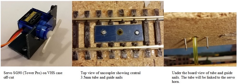
A sprinkling of ballast over the top of the ramp will hide it nicely. That's the 'plan'.
I had hoped a few more items might get installed before the festivities get fully under way - some street lighting at the rear of the terminus and a set of traffic lights. Then once all the uncoupling ramps are installed I can get on and get the ballasting down, followed by the platform lights.
That's it for now. Soon be time to down tools and enjoy the festivities for a few days.
Here's wishing you all a peaceful Christmas - I hope Santa brings you whatever is at the top of your wishlist.

Posted
Full Member
I do like the look of your station, very nice. I’ve only used the Peco ramps/standard couplings on Woodside and found them to work reasonably well, but adjustments to get some couplings at the same height is needed on a fairly regular basis. Two methods I’ve used to disguise the ramps – in stations, darkening the ballast around the ramp – particularly Woodside Station, where the ballast is fairly dark to begin with near the buffers and in the marshalling yard putting the ramps ‘in’ the boarded crossing. Also, with the overall roof at Woodside, the ramps can’t really be seen. On Woodside station I’ve put a baggage trolley on the platform perpendicular to the track at the centre of the ramp – makes ‘seeing’ the ramp very easy when trying to uncouple an engine. In the fiddle yard I’ve got marker posts to do the same thing. No doubt all your computery stuff will be able to stop the train exactly over the ramp, but we simple souls need some help. I’d caution putting ballast on the ramps, certainly with my simple set up it could be that the coupling ends up between individual stones and then may not lift the coupling sufficiently to operate properly – if you see what I mean. If this is all rubbish, and I’ve got the wrong end of the stick, not unusual, please ignore.
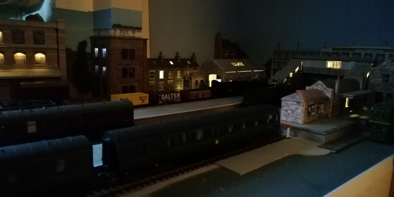
Couldn’t agree more about lighting – definitely does bring a layout to life, day or night – and yes, don’t just light every ‘room’ – much better just to box in a couple of rooms or floors in a factory, and vary the brightness too, it all helps.
All the best for the festivities.
Keith
Do I have a plan? Na, if I did I'd spend most of my time trying to remember where I put it.
Posted
Full Member
All my computery stuff, as you kindly put it, doesn't stop the trains - that part of it is still manually and visually needed to make the 'stop' in just the right place. OK, so I use DCC, but it's still a visual job. Signposting is a definite must fit.
Where the computer thing comes in is to remotely activate the uncoupling ramps, mostly in places where I'd not be able to physically reach, or it would become too fiddly to use some form of manual rising mechanism. It seemed a good idea at the time, sounded promising - at least in my own mind!, and others have had a go at it. Not sure of the success rate, but who's counting?
Once we get the festivities out of the way, I'll give it some more thought and have another bash at it. There is already a glimmer of thought of one way to achieve what is required but…… I'll leave that for a last ditch method.
All understood about the ballast on top of the ramp possibly fouling the uncouplers - maybe I'll need to give that some more thought and just colour the surrounding ballast to that of the ramp itself. I'll keep posting on progress - one way or the other.
Anyways, have a good Christmas - here's to you and your family (and also to other readers of this thread).
Cheers
Dave
Posted
Full Member
Hmmm! Not overly good progress initially - but finally, there is success. After many attempts at getting the program to function correctly (worked ok in simulation mode) and having spent a fair amount of time trying to get the servos to operate on the bench I found they kept twitching whenever they're not operating. When each servo is called to raise the ramp, it works nice and smooth, taking around a second an a half to lift (nothing too fast or jerky), and then slowly drops down again after around 10 seconds. And then, while in 'doing nothing mode', they all just twitch every few seconds. And this is where I was having a problem - getting rid of the twitching. And I've had to break out my trusty old oscilloscope to see if I could figure out what was going on and causing the twitching - all to no avail. I could see the pulses ok and also whatever was causing the twitching - certainly not the servo(s) themselves. Nice to see the waveforms though! So it was all down to the software/my programming.
A question was asked on the relevant forum and a few suggestions came back to me, such as power rail and layout and decoupling (capacitors) and some programming hints - there's some commands there I've never come across before and in routines that do not use the - what might be considered - 'normal' servo commands.
A change I made, initially to try to be rid of the twitching, was to use a more substantial power supply rather than my trusty old (power limited) item built many, many years ago. Break out an old, redundant computer power supply. Now that should be able to provide enough power for the entire layout. Currently 12v, then a 7805 regulator to the chips and 5v to the servos - nice and totally separate supplies, and hopefully nice clean supplies.
But, thanks to those guys on the PICAXE forum who kindly offered code samples, I now have a working mechanism that can uncouple tension locks remotely. It still needs to be mounted onto the layout though, but I'm now able to make slight adjustments to the code to make it do what I need it to do; and without twitching! What's more, the same code - with a few minor changes - can now be adapted to operate and control other bits of kit still in the thought processes of my mind.
I should add that this uncoupler design is not entirely new. I have compiled it from a number of designs - Alan being one contributor on RMWEB some years ago and also an 'N' gauge design (author currently unknown, sorry) as well as a few other contributors to my research.
The following photos were taken using a spare length of track on a scrap piece of baseboard material.
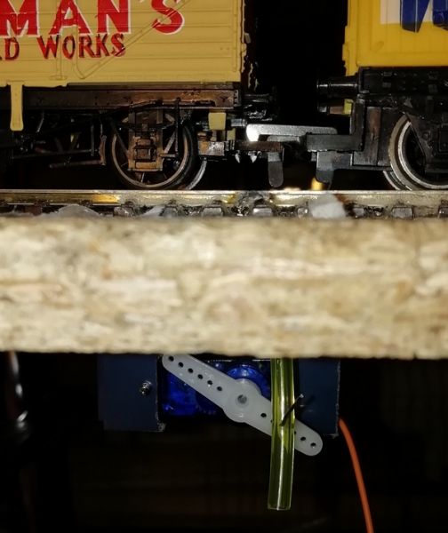
Ramp in the lowered position.
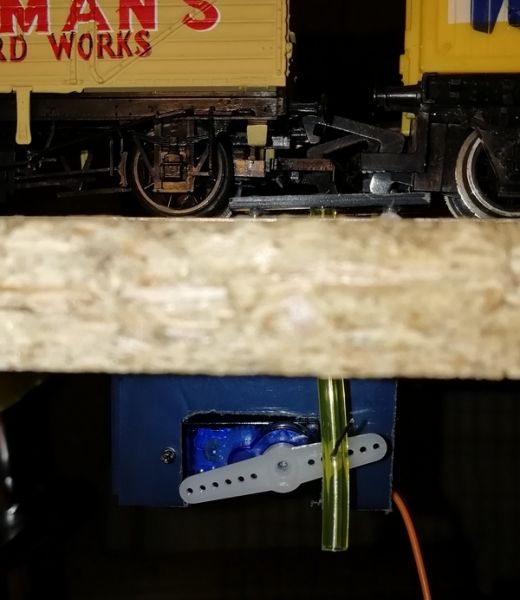
Ramp in the raised position.

Under the baseboard before the servo gets fitted showing the activator tube and the guide nails.
Again for completeness, the servo is a Tower Pro (others are available) SG90 9g, the mount is an off-cut from a VHS tape case, the uncoupling ramp is likewise ex-VHS, the tube is a short length of flexible 3.5mm tube with the short link to the servo arm an off-cut of wire (from a resistor) and a pair of thin 25mm nails as guides. The ramp lays on the baseboard (sleepers cut away) and needs to be raised by around 9-10mm. The controlling chip is a PICAXE 18M2+ with a rotary selector switch (for 6 servos) and a push-button activator.
All I need now is to transfer the design (many times over) onto the layout in spaces where a mouse would have little headroom! That'll be 'fun' - or not, as the case may be!
Posted
Full Member
What a job that was! Talk about difficult, frustrating, and a pain in the right arm. Not easy fitting a servo on a bracket to the underside of the upper baseboard when there is only 85mm clearance between that and the tracks on the underneath board and the fitting is at near full arm's length away; not to mention you can't see what you're doing, such as putting in the bracket mounting screws (due to the logistics of where my head is located in relation to my arm and shoulder - head above the top board and arm under it) and the screws being at the back of the bracket and only visible in a mirror. Now, if I were a contortionist…..maybe with x-ray eyes….
So it was a case of curse and curse some more till I managed to get the bits fitted. And to think this is the first of possibly 12 (maybe more) ramps to fit. At least this was the worst of them all (I hope).
Only two small changes from that described in my last post, and that was for a stronger piece of linkage wire between the servo horn and the tube. I found, almost as expected I guess, the wire offcut used was too flimsy. This time I've used a length of 1mm copper wire (from some old twin&earth cable) - this provides a tight fit to the holes in the servo horn and is strong enough not to bend. Seems to do the job just fine. The other change being that the ramp lowers after 5 seconds; 10 seemed a little excessive (but that's trial and error programming).
No photo of the finished/fitted item at this time as it's not a million miles from the prototype posted previously (post #81) - a little longer, but that's all. It'll look better when I get some ballasting around it, maybe on top of it also, but at least it will be blended in to the surrounding trackwork. But I want to get some more ramps fitted before starting to do the ballasting. Hopefully, the next ramps will not be quite so awkward or take so long to fit.
Posted

Site staff
I understand those type of "modelling" problems Dave and the older we get we seems to get less flexible in arm & head movements and the eyes don't want to see what we want them so see either.What a job that was! Talk about difficult, frustrating, and a pain in the right arm. Not easy fitting a servo on a bracket to the underside of the upper baseboard when there is only 85mm clearance between that and the tracks on the underneath board and the fitting is at near full arm's length away; not to mention you can't see what you're doing, such as putting in the bracket mounting screws (due to the logistics of where my head is located in relation to my arm and shoulder - head above the top board and arm under it) and the screws being at the back of the bracket and only visible in a mirror. Now, if I were a contortionist…..maybe with x-ray eyes….
But outside of that, looks the goods….
Ron
NCE DCC ; 00 scale UK outline.
NCE DCC ; 00 scale UK outline.
Posted
Full Member
Having said that, we bravely battle on. One day the layout will be finished (if layouts are ever fully finished?).
Not been able to get much done over the past few weeks, but hoping to get back in there this next week to finish off the next few ramps and get them working.
Dave
Posted
Full Member
One or two problems appeared along the way - don't they always.
Originally I used a 7805 regulator to control the +5v supply voltage to the servos (only 4 of them at that time of testing) and the device got horrendously hot very quickly - so that was a non-starter. To fix this I then switched to using an old PC PSU which I knew had more than enough current capacity. At the same time I swapped to a different software command to move the servos and, at the same time, to get rid of the twitching effects noticed. I did a 'Google' on the current taken by these small servos and found that they could be quite current hungry - something approaching an amp per device - which I was surprised about. Anyway, since installing all six servos, I've now taken the time to measure the current taken by them - with interesting results. The original 4 took a lot more current than the latter two - all servos used (different batches) have the Tower Pro SG90 brand name. At peak current, while each servo is being operated, the original 4 took around 650mA each while the 2 newer ones took only 110mA. That's a heck of a difference between two batches of what is supposed to be the same servo. With the servos quietly doing nothing much I measure around 30mA average, and a peak reading of not much above this.
Certainly something to bear in mind when next using servos - not all (even of the same [stated] make) are rated equal.
Anyway, they have now been set up (a few minor height related tweaks may still be required) and covered over with a layer of ballast so that they can hardly be seen - from a distance, anyway!). There's no way that these things can be totally hidden, but once they and the rest of the ballast get a coating of "muck" they should blend in a bit better.

Now that all the ramps are (finally) in place, and following various complications such as under-board point activation rods, cabling runs and track powering connections getting in the way (together with a need to make up a small mimic board with some very small SMD LEDs - this is still in progress), I can run a few more trains and easily, and at the push of a button, do the uncoupling and allow the loco to move away.
If I thought fitting these 6 were difficult, the next set in the marshalling yard will be even worse. Maybe I'll skip these!
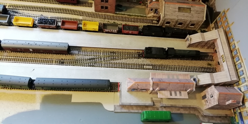
I've also taken the opportunity to add some ballasting in the terminus, plus a bit of ground scenery. The Terminus is starting to look something like at last. Also added, has been a very low relief customization and cut-down version of the Model Railway Scenery's 1930's Factory - complete with the obligatory lighting in some windows - this item covers the door frame of what was a fitted wardrobe with the doors removed. The lighting being provided by 0805 SMD LEDs - very fiddly to solder to due to their very, very small size (2.0mm x 1.25mm), some 38swg enamelled wire, 25watt iron and my ham-fisted fingers! It's not easy stopping these miniature LEDs moving around while trying to solder to them.
There's still a fair amount to complete on the Terminus - such as platform lights, people, more ballasting, roadway….. The list goes on.
Next up… After a bit more fiddling on and around the Terminus, a start on some scenery together with a tunnel entrance near the halt station.
Posted
Full Member
Posted

Full Member
Michael
Posted

Legacy Member
And your uncoupling arrangement seems to be working well after sorting the usual teething problems.
You will be able to play trains properly once you have fitted the others without the hand of god then.
Brian
OO gauge DCC ECOS Itrain 4 computer control system
Posted

Full Member
I’m not looking forward to soldering SMD LEDs but as I’m modelling in N scale I think I’m going to have to give it a go for street lights, etc.
Posted
Full Member
Best of luck Marty when you start with the SMD LEDs; with the size of those things you'll need a magnifying glass as well as nimble fingers! One hint I saw the other day for soldering to these things was a length of double-sided sticky tape (or ordinary tape doubled over). Must try that!
The (very) low relief factory around the wardrobe door post is only 6mm thick to the outside wall, not including the parapet - the front facing wall is even thinner, hence no lighting here; no room! The side facing wall has 2mm thick card as the outer wall and 4mm of internal spacers (to give some depth) on which I needed to fit the lighting - the SMD LEDs face rearwards from the back of the front wall to reflect off the rear panel. I'd been trying to figure out what I could do to camouflage that post for some while without the need to simply stick on a picture of some factory or housing or what-ever. I think it works ok - and it meant I could add the lighting to it as well to give it that feeling of depth and usage and to actually being a building rather than a flat picture. I think the brightness of the LEDs might need increasing though; at the same time as reducing it in the terraced housing (these are a bit too bright I feel). It's all these little tweaks as the area gets more complete; in isolation each part looked fine.
I took a bit of a diversion over the past day or so. I decided I was fed up with the jerky nature of my Lima Class 117 DMU (circa 1983) at slow speeds, despite a good and thorough clean up. It was fine once a bit of speed had been gained, but slowing to a halt was hugely upsetting. Just the nature of the 3-pole motor, I guess.
So I decided to upgrade the motor from the old original pancake motor to an old CD player drawer motor. Calling on the usual selling site, a new 8-tooth gear and a small length of thin brass tube (for alignment purposes) soon arrived. Add to this a couple of back-to-back 1N4148 diodes (2 in series each way) and a generous helping of hot glue to hold the motor in place soon had it up and running. Hopefully the diodes will cope with the current being drawn (measured at a maximum of 100mA free running motor). At the slowest speed step, which is quite slow and steady, it does suddenly stop and no amount of tweaking with the dither settings makes it any better. But it IS a huge improvement! I may have a play with individual speed steps to see if i can improve it further; but I;m not holding out a lot of hope in that direction. Maybe another diode or two……?
I wonder whether my old Lima Class 33 (circa 1986/88) would also benefit from an upgrade, or my Hornby A4 (1979), a similar motor but with a different housing I believe, and an 11-tooth gear. I'll think about these for another day.
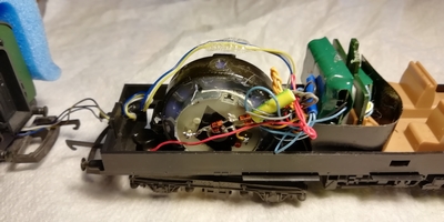
Quick photo of the motor upgrade. Fitted with TCS MC2 decoder with Keep Alive module.
The wires going between the units is for front/rear lights fitted back in 2013 - from http://www.blackcatteck.co.uk.
Posted

Full Member
Posted
Full Member
Dave
Posted
Full Member
It does have tags and I soldered directly onto them, but it didn't work. I was wondering if maybe there was some trick to soldering stuff to them properly. I'm rubbish at soldering, mind you.Maybe I was lucky (or maybe your CD motor didn't have any tags) but I just soldered direct onto the two tags on one side of the motor (the side away from the spindle that goes to the gears) - the diodes went direct to one tag while the other (return) wire went to the other tag. Surely, your motor must have had some form of connector - be it tags or a plug/socket arrangement, or else how could it have had power applied to it.
Dave
Posted
Full Member
No idea why it might not work. Could it have been from a faulty CD drive (motor u/s)? Could you measure any voltage on the tags of the motor when it failed to work? I'm assuming there was voltage getting to the track and onto the motor. DC or DCC?
There's no special issues to soldering to these tags - unless, maybe, if too much heat was applied or for too long and the internal connection got lost.
No real answer for you I'm afraid without getting some test gear to it and checking what's what with it.
Dave
Posted
Full Member
One other thought came to mind regarding your CD motor not working…..
Did you install/fit any diodes between the supply/decoder and the motor? If so, one of them may have been bad or not fitted in the correct polarity/orientation. Back-to-back diodes are needed so that the motor will run in both directions (as per the top drawing).
My two pairs of diodes are connected as per the bottom drawing, i.e. between the pickups (DC) or decoder (DCC) and the motor:
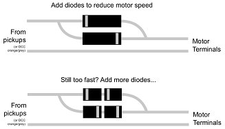
My slow speed (at step 1) is quite slow and steady but still relatively fast such that I get a sudden stop when going from step 1 to step 0. So maybe a few more diodes are needed; maybe even a resistor across the motor terminals might work hopefully without drawing too much extra current from the decoder - maybe I'll give that a try one day! I'll check the diodes first in case they have gone short circuit. I don't really want to fit any higher rated diodes due to their additional size and somewhere to fit them is concerned (1N4148 are ok size-wise - maybe I could find some SMD versions of the 1N4001 diodes [higher current capability] - they might be easier to fit somewhere out of the way of the motor).
Dave
Posted
Full Member
Posted
Full Member
After a bit of a problematic testing time with the new CD motor in the Lima Class 117 DMU (post #93 & #98) whereby speed step 1 seemed rather fast and being unable to get it to slow down further by various decoder settings, it has now been much improved.
The original notes I had read indicated adding two-by-two diodes back-to-back to reduce the voltage being applied to the motor (0.7v per diode drop). As the speed was still fast on speed step 1, I initially thought that by adding an extra diode-(or two)-pair it would improve the slow running as it was effectively further dropping the voltage being applied, But no; quite the opposite, it made matters worse by running faster. Eh? How does that work?
So now, instead of the 2-by-2 diodes back-to-back, I just have a single diode back-to-back and things are much improved. I still need to tinker with the mid and high volt settings and maybe a couple of others to achieve a more normal (higher speed) running, but I'm happier now that I can get the DMU to run very smoothly and quite slowly to a stop. I consider it a success.
Also, there's now a small mimic board for the uncouplers in the Terminus area using SMD LEDs to make life easier than just having a loose 6-way switch literally hanging off the processor board and me not being totally sure which uncoupler is being lifted. Another small success.
And now, back to getting the Terminus finished (well maybe!).
MEMO to self:
stay focussed on one thing at a time! (My mind tends to wander onto building other sections around the layout).
Some hope!
1 guest and 0 members have just viewed this.