John Street - BR(E) - 1960
Posted
Full Member
My second bash at model railway-ing
Very fast reply from AA - and, yes, they can supply just the post-mounted Position Signals - no electrics, just two white LEDs - but the price, at least in my mind, is a bit pricey given that I would be looking for (probably) eight of them. Makes the job somewhat prohibitive.So, at the moment, it's back to the scratchbuilding with - using the Blue Peter methodology - sticky backed plastic sheeting and some miniature LEDs I've already got lying around.
So it's a case of watch this space - but don't hold your breath in the meantime; this may take quite a while to sort! So it's back to platform building and a few other what-nots before I get to thinking about building these lights.
Dave

Posted
Full Member
I would agree that AA are by no measure the cheapest, but as ever in this world, you get what you pay for – and in my humble opinion Matt really does produce what I consider some of the most accurate model signals on the market. I’d just try one position light, see how it looks, then you’ve got a template for the rest…..
So you’re another Blue Peter follower…. must admit I use that methodology all the time…
Incidentally, the two paragraphs in post 59, which is all about chips and stuff makes me realise what a good decision I made at the start of this second stab at model railways (steer clear of all this DCC nonsense and expense) – that’s not modelling – that’s computing!!! I fear I am in an ever decreasing minority, but I’ll keep flying the flag for the original, and best, DC. At the end of the day of course, each to his own, but for me – better the devil you know. Ah, ZX BASIC… memories, memories… personally I was a simple FORTRAN man, never really got into FORTRAN77, despite the Lab having written a couple of compilers….. but that was all a seriously long time ago…..
Incidentally you sound like I did when I was battling whatever lurgy it was that was doing the rounds here – certainly the better weather did improve things. I have to admit that three days hard graft in the garden getting this pergola so that it now looks the part and has reverted to being the support rather than the supported has also helped…. trouble is the gardener now has other jobs in mind…. at least the weather taking a turn for the worse, again, has stemmed the flow of ideas in that department for now.
Keith
Do I have a plan? Na, if I did I'd spend most of my time trying to remember where I put it.
Posted
Full Member
Over recent weeks I've been having a look at creating some backscenes from photographs and having a 'play' with some software that 'stiches' together and merges a number of sequential photographs onto one long picture. There are a number of freebie packages available - the one I've been looking at is Image Composite Editor (ICE, from Microsoft). Another package (though not installed) is Hugin'. Then there's Adobe's Photomerge, part of the Photoshop package. A quick net search will bring up many such packages, many of which are freebies. I like freebies!
I've not entirely got to grips with ICE yet as far as making the picture a suitable scale size for the backscene contents - but with a quick load of two pictures taken some years ago it seems to produce a well blended/matched output. All I need now is to find a shop somewhere that can print long banner-type images onto decent quality paper once I get to grips with the scaling of the output image. My printer, like most I would guess, is only capable of standard sized papers, A4, A5, etc. My old dot matrix printer (retired many years ago) would print banners of any length - in black and white. I guess this is what they call progress.
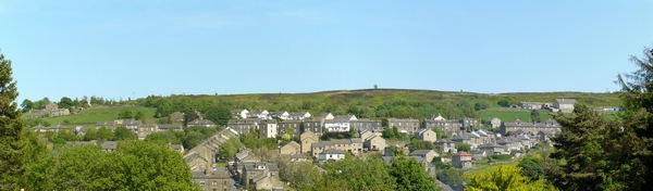
This is output of the stitching together of the two photos mentioned (size and quality much reduced).
My camera will do a similar thing, a panorama shot (I think a maximum of two photos only though), but even this I've not entirely gotten familiar with, and there is no way I've found where the result can be scaled ready for printing at the correct size. No doubt there is a way, but I think the software will probably do a better job if there are multiple photos to stitch together.
Plenty of time to do more research on all this. Now back to where I left off - something to do with building a model rail layout I think. More to come in a week or so when there's something to report.
Dave
Posted
Full Member
I've made a little progress (in my mind at least) regarding them. I've seen some very small SMD LEDs (currently on order from the Far East) and these will (I hope) be sandwiched between layers of black plastic and cut down to the correct size/shape. The theory appears good but I'll not know the final outcome until I get hold of the LEDs and start construction. But the idea is there! The LEDs are 0805 SMD types - the size is 1.25mm x 2.0mm x 0.8mm - I just hope my fingers can handle and add wires to such small components. The LED lens is just oversize for the size of the aperture they need to shine out of. Hopefully, they'll do the job. But there's plenty I would still like to get done (finished) before I start on these.
Right…..back to the drawing board and to progressing other parts of the layout while I wait for the post and the LEDs.
Dave
 Last edit: by spurno
Posted
Full Member
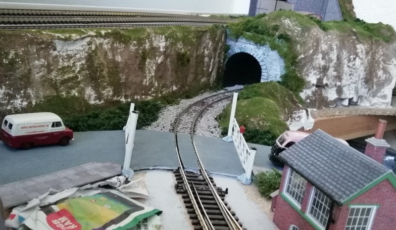
But I do seem to have been concentrating around the area south of the Halt station - I really must give it a name! In fact just about everything between the two tunnel entrances has been worked on over the past week or so. More needs to be done on the Halt itself before I can upload anything relating.
There's been some rusting of the rails towards the Halt, together with some ballasting along that bit of track. The 'south' tunnel entrance itself and its surrounding hillside has been modroc'd, painted over (Woodland Scenics C1221 Raw Umber) and a few bits of various (Woodland Scenics) greenery have been added. Possibly a few 'trees' will be added at a later stage.
I've been raiding the garden for some off-cuts that "might" make some half decent trees. After a lengthy search, I came up with the name of a bush we've had in the front garden for many a year - rubella (skimmia japonica). The flowers are just coming out and with a bit of hairspray and/or spray paint with some additional greenery thrown on, it might look just the job. The jury is still out on this at this time! It might work - it might not. First impressions of having used a spray paint and a sprinkling of "leaves" might appear to be a workable idea. I'll know more when the entire flower heads totally dry out and any additional work that might be needed is carried out.
A level crossing and approach roads with some pavement strips have been (loosely/not fixed) added at the end of the Halt and siding together with its associated signal box - note the small area near the left pavement awaiting some modroc!. The level crossing gates are simply 'propped' upright with blobs of Blutak at this time (having come from my old Langley Junction layout where they were a fixed & unmovable item). Hopefully at some stage in the future a new kit will be purchased and I'm hoping the gates will then be made to open/close by means of servo motors. Some research has been going on but I fear that may be quite some time away.
Looking back at an early image of this area (below)……Ugh! Newspaper fillings on the hillside; no tunnel entrance, just a hole in the layout; the crossing gates held upright with screw terminal blocks - and no road. What a difference a week or two can make!
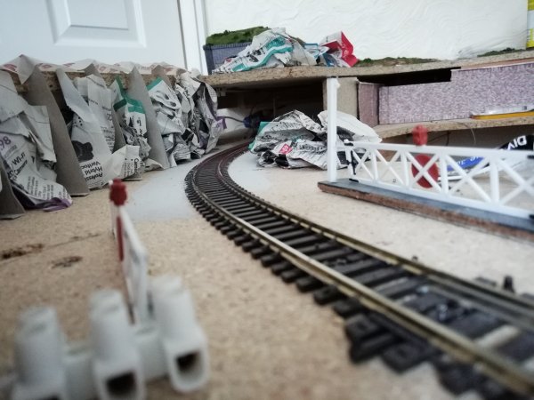
When I started this item, I said not much had been done. Having read over the above, I'm not entirely sure it was the correct statement! Quite a lot appears to have been achieved. And that was a surprise in itself.
So there is progress being made - not always where I'd rather be working, the Terminus and the Turntable; but it is still working towards a finished idea (not that it will ever be finished, of course; these layouts never are!).
Watch this space for further updates and ramblings from John Street. Cheers for now…..
Dave
Posted
Full Member
I've now given the heads a spray with some green paint and with a moderate sprinkling of Woodland Scenics leaves I think they will look just the part once they dry out a bit more and get "planted" on the layout; a bit of work yet to do on the trunks. All nice and varied in size and shape from around 10ft to 40ft scale height.
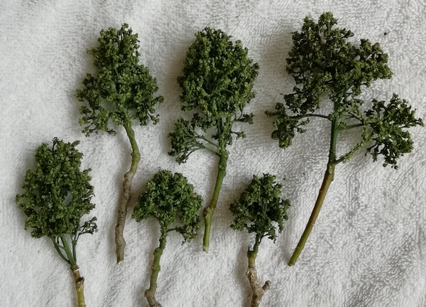
As a result I've been out again and decimated the bush further - selective pruning I call it! So in a day or two they'll also get a blasting from the spray tin.
Cheers
Dave
Posted
Full Member
I’ll have to have a word with the gardener about rubella, don’t know what it looks like, but it certainly looks like a useful source of trees… are these the new flower stems, or just leaves? I always thought rubella was something to do with measles…. I’ve still got some dried buddleia heads in the loft to be going on with for now – but these look a lot more convincing. Perhaps I should get out in the garden a bit more…. Na, perhaps not.
Keith
Do I have a plan? Na, if I did I'd spend most of my time trying to remember where I put it.
Posted
Full Member
As you say, I always though rubella related to measles. You learn something new every day. It took me quite some time to find the name of the plant - not easy when you only enter a vague description of the flower heads to do the search on. Google can be so frustrating at times!
I think these flower heads look far more convincing than the buddlea flower heads and they can look pretty good themselves. To see what the plant looks like, take a trip to the RHS web site.
I've not seen too many of the plants around, certainly not in my village. No doubt any reasonable garden centre will have them on show. This is the right time of year for the flower heads to come out a fragrant white after being in a red closed state since late winter. I've caught them just before the white flowers have fully opened out.
I've planted a couple of the "trees" on the layout late this afternoon and they do look quite good (certainly from a distance!). I'll get a few more planted over the coming few days or so and post another picture or two when there's a bit more to show around the (as yet un-named) Halt station. But with the Bank Holiday coming along and the Tour de Yorkshire passing this way, time in the train room is likely to be limited for a week or so.
Anyway, keep on trucking and shunting the trucks, etc.
Dave
Posted
Full Member
I also thought I would prefer some better grassy areas than just a sprinkling of flock onto and around the area. This involved researching the subject and eventually building a Static Grass Applicator; my build is here: (http://yourmodelrailway.net/view_topic.php?id=15726&forum_id=56&jump_to=281141#p281141). P.S. Not my design but is simply my "take" on it. So that's taken time away from the layout.
And so these and other jobs went on and on, etc. ….. Anyway…. So this is a rather lengthy update to fit it all in relating to this one small area of the layout. So forgive me for the following, I was never much good at precis at school! (And that was a LONG time ago!).
A nice long and warm late Spring/early (swelteringly hot) Summer period over the recent weeks or so hasn't helped the model building (or the garden!) but…. At long last I can report….. The turntable has been completed and put into place. Hurrah!
It's taken quite a bit of doing. Going back a couple of months or so and after many fruitless attempts at getting it to rotate properly, I needed a jig so that I could work on the underside of the turntable away from the layout as it was impossible to do so with the very limited height between it and the hidden tracks that run underneath - only around 90mm. An old kitchen cupboard door with a suitable hole cut in it provided the means for this. The indexation disk had became slightly distorted - due to various causes - and with the rather small (3mm) gap between the InfraRed LED and its associated sensor made the overall flatness of the index disk quite important - this is where I was having problems - the cut slots were catching on the sensor edges (a slight filing down of the leading/trailing edges of the LED/sensor unit helped with this). Also the screw fixings on the coupling between the turntable spindle and the motor became stripped of their threads (that's me being a bit 'ham-fisted'!); so fresh, larger screws had to be found and utilised (this didn't help the index disk and its distortions - the screwheads were a bit large and pushed against the disk distorting it slightly).
One modification made to the (Locomotech) motor kit was the addition of a small relay close to the turntable to do the rotation direction changeover as I found there was too much voltage drop on the thin cables I've used that would otherwise have carried the motor current between the mimic/control panel and the (remotely placed) turntable. Not only that, but I had to by-pass the bridge rectifier when supplying a 12v dc voltage to the pcb. Just a little too much voltage was being dropped across the rectifier to make it properly functionable.
One issue I've had with the indexation disk is the width of the cut ('stop') slots (not that they could be cut any thinner); and not that I can do anything about them. Turning anti-clockwise I can adjust the disk to stop the turntable correctly on all but one position; but clockwise it stops a little (varyingly) short of where it needs to be on all positions - off alignment enough to cause a derailment. With a bit of tapping of the 'rotation start button' I can nudge it forward to the correct position before it goes whizzing round (albeit slowly) to its next stop position. And adjusting the 'Brake control' makes little or no difference to the actual stop position. Anyway, it is usable and is now functional; I just need to remember the clockwise alignments - and to have my glasses on as the turntable is some distance away from the operating position.
Following on from the turntable, as this is in the same area, came the Small Engine Shed (Scalescenes R021a) - nice kit. Various layers of card of different thicknesses make up the height of the "concrete" floor to the level of the track. Some concrete-colour paint added to the card and some lighting (yet to be done) completes the project. I had thought about cutting out an Inspection Pit - then thought better of it. A reasonable job of it was done as a "try-er" on a spare piece of track but given the angle of the Engine Shed from the viewing area, no-one would ever see it, not even me! So the idea got ditched. Why make additional work!
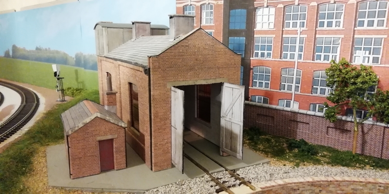

Then there's the small Crew Room (Scalescenes T024 - Weighbridge [!]) located off to one side of the Engine Shed - that was supposed to be for another day but I couldn't resist building it! It was supposed to be a bit of a 'quickie' to put together. But it took weeks to go from start to finish - "Life" got in the way. As it does. Some lighting here also required.
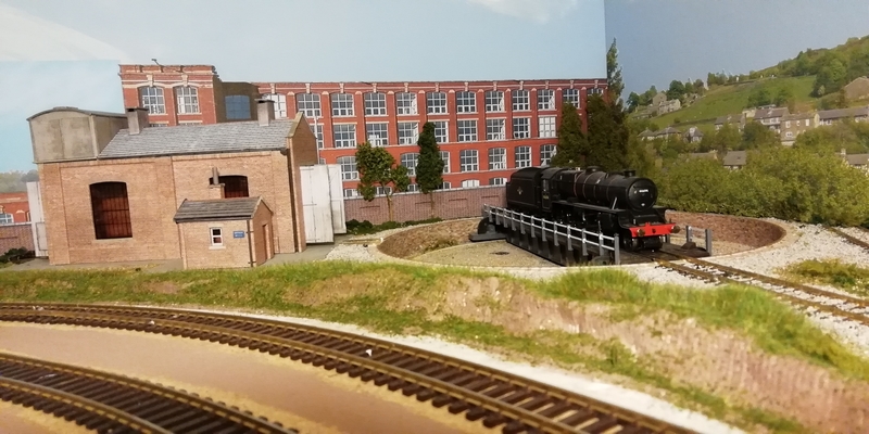
As you can see, there's been a bit of scenic stuff (including the static grass!) added around the turntable and also in front and to the side of the Engine Shed.
A few trees have been added, mostly to blur the transition between backscenes in the corner. A few more trees will be 'planted' as time allows.
And talking of trees…..
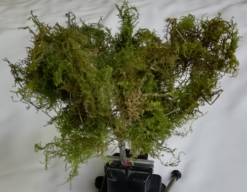
I've also had a dipping of the toes into making "wire trees". So some old BT solid core wire (stripped of its insulation) was pressed into use together with some moss dragged from the garden some 12 months or more ago and stored away and now simply "thrown" onto the bare wire (no adhesive yet). All it needs now is a light coating of polyfilla to hide the wires in the trunk and a coat of grey/brown paint to the wires. I think (from a distance) it looks pretty reasonable. Sufficient for my needs anyway. This, when it gets completed, will probably represent an age-old tree (due to its size) as a 'feature' when I get further into the wider scenery areas across the layout.
This was just a try-out - seems to work relatively well, if a little large. But that can be easily rectified with a few less wire strands and shorter lengths of them.
Right then; it will soon be time to move on towards getting some more work done to the Halt station and the area surrounding it - if I can keep 'on track' that is (pun definitely intended!) and not to deviate from the plan (yet again!). Or shall I make a start on the Terminus platforms? Time will tell over the next week or two. Must think of a suitable name for the Halt station! Watch this space to see quite where I move onto next.
Cheers for now.
Posted

Inactive Member
Max
Port Elderley
Port Elderley
Posted
Full Member
I have now completed the Home Approach Signal which will remain at Danger until a train approaches when it will auto-change to Clear together with a platform number display but only if the approach road over the cross-over points is actually clear and then to auto-return to Danger once the cross-over has been reached.
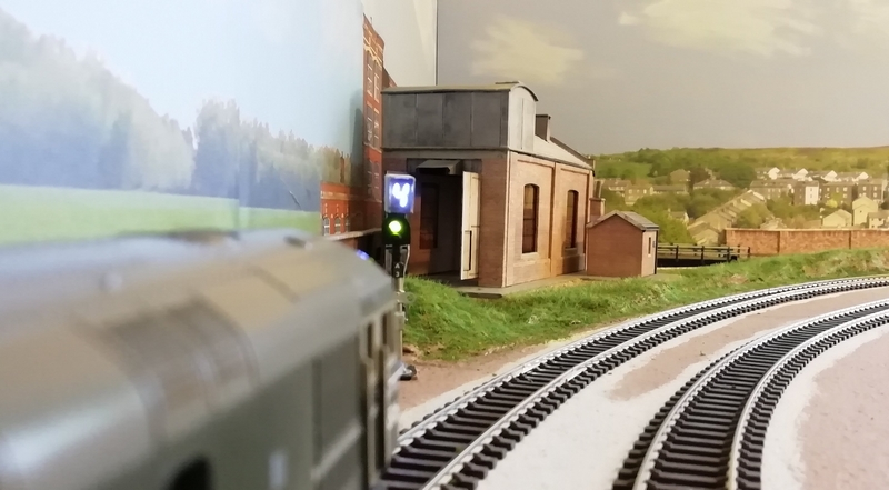
D6506 Class 33 on approach to the Home Signal and Platform 4
Post #59 shows the signal/display in close-up. The circuit board below it has been further developed from that point and populated with a load more ICs, etc.
I've used RPR-220 infra-red LED and sensor pairs buried under the track between sleepers together with an LM339 comparator feeding into a PICAXE chip to control things - activated by a small silver foil strip under the loco. The display is also driven from the PICAXE into a 4511 BCD decoder. I prefer the PICAXE system as it uses the BASIC programming language - I never got to grips with much else or I might have used the basic PIC chips or Arduino bits and the C language.
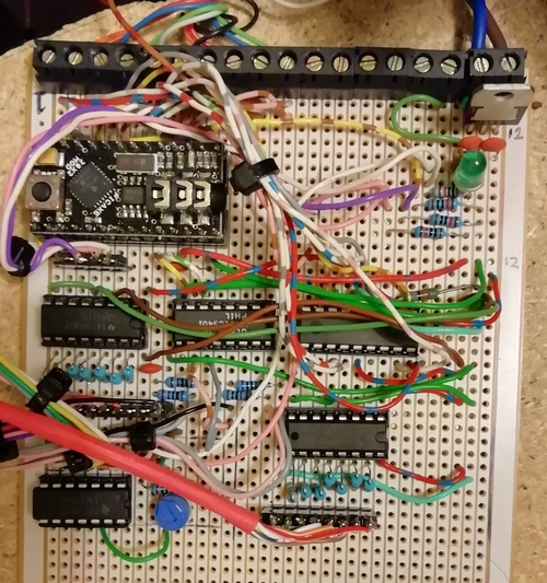
Home Signal & Display Logic PCB
Probably not the tidiest of pcb work, but this is what happens when a Plan(?) get progressively added to as and when it gets thought of!
This is the start of what I hope will be a fully interactive signalling system across the layout and is based upon the traditional "block system" by knowing a train has passed one signal but not yet clear of the next. No track current monitoring required - just under-track sensors watching for a train to pass over it and some cunning programming. There's no actual "track" isolation sections should a signal be at danger; as with the real thing, it's up to the driver (namely me!) to actually stop the train in good time.
I've also built another display unit to sit on the mimic panel as an 'always on' duplicate of the Home Signal Display. Makes life a little easier to at-a-glance see which platform is live to the layout. The use of another PICAXE chip and 4511 completed this little 'add-on'.
Will I ever get round to getting on with the Halt Station? Actually, no, not yet; but plans are on-going relating to motorising the level crossing gates - that'll be interesting!
I think I'll start on the Terminus next. Watch this space, you never know where I'll wield the soldering iron or glue…..
Posted
Full Member
Impressive stuff… although how it all works with all those chips and pickaxes is a bit beyond me - BASIC and C rings a few bells mind, well perhaps one bell…
Keith
Do I have a plan? Na, if I did I'd spend most of my time trying to remember where I put it.
Posted
Full Member
Your layout and electronics are great, looking forwards to future updates!
Posted
Full Member
Re the turntable, I used the MERG turntable controller with their recommended stepper motor and gearbox from RS Components on my Peco Turntable and it worked a charm, you can have up to 16 positions and they can be anywhere on the turntable, you just lay the track as you want then calibrate the turntable to the track. Works every time faultlessly.
Total cost is around £80 but most of that is the motor and gearbox, you may finder a cheaper option if you understand stepper motors and their spec, I don't so just went with MERG's recommendation, and more than happy I did.
Paul
Last edit: by Paul-H
Posted
Full Member
Thanks Paul for pointing me in the direction of the MERG kit. Regrettably I've not joined the group so can find little or no information on it or how to put it all together and set it up. I appreciate instructions come with the kit but I always like to know what I might be letting myself in for before taking the plunge (including joining the group) and exactly how customisable stop positions are as a retro-fit to an existing set-up.
There are a few videos on YouTube which I will study more at a later date. But, in all honesty, having spent out on the Locomotech kit I am slightly reluctant to try to get further funds past the 'chancellor' for something that does already actually work, albeit with a bit of tweaking. I'll certainly be keeping it in mind.
As you can see Chris, my circuit board building is, like yours, close to a zero point. I'm ok with stripboard but that's as far as I'm prepared to go these days. You'll notice I've not posted any pictures of the reverse of my stripboards - not a pretty sight! I did try etching a few boards many years ago when active with the Ham Radio and found the boards to be not a great success. Maybe things might be different at DC frequencies rather than HF. But now that there are so many multi-pin logic devices around rather than the wide-spaced legs of a transistor, it's probably going to be even less of a success story.
And incidentally Keith, a little bit of programming with BASIC is dead straight forward(-ish). It's almost like posing a question in English and then reacting one way or another with a few other simple (English-like) commands depending on the result. I knew nothing about programming these processors until recently - it's been a learning game and, although I may seem to be promoting the PICAXE system, I've no connection to them. There's an editor that gives hints as to where you may have gone wrong with a command and it even programs the processor without anything else (other than the cable). The number of times I've had to refer to the manuals for the correct instruction layout, I simply can't count them. I have used a bit of BASIC programming in the distant past when I had an old ZX Spectrum to play with (it's currently residing in a tea chest in the garage - why I've still got it, I have no idea other than for sentimental reasons). PS As I said, I've no link, other than as a buyer of a few bits, to Revolution Education (the makers of the PICAXE system - it's mainly aimed at school kids as an intro to computer programming). It's surprising quite what can be done with these devices.
Cheers
Dave
Posted
Full Member
The layout has been idle for quite a time while working on parts of the layout (and during the summer of course) and a few of the locos would no longer run smoothly - disappointingly sluggish to say the least despite the track having been cleaned. So I decided to do some serious maintenance on each of the stuttering locos (and check the others over also while I'm at it) - an ageing Lima Class 33 (always been a good runner - till recently) has been renovated and now runs nice and smooth again. Also, so was my (also ageing) Lima Class 117 - just waiting for some lost (no idea where or when?) traction tyres for the 117. I was surprised at the amount of muck and corrosion that had built up. Then I found a number of points across the layout (8 in all) that failed to switch/change-over. These have been down to:
i: a few linkages needing a slight adjustment, - done!
ii: a diode matrix error for a three-way point was causing problems - the matrix was fine as designed, but the connections got totally screwed somehow; so rewired from the start, - done! and then
iii: three of the MOSFET coil drivers having failed; these have now been successfully replaced - done!
I got to thinking as to "why" they failed (MOSFETs are pretty rugged devices) - then I read the spec sheet, checked with a DVM as to the (peak) voltage being applied to the 'Gate' and found it to be 11.7v, admittedly in a short pulse, whereas the spec sheet says it should only be a maximum of 10volts - and this is from sticking to the original design of applying 12v across a 22uF dc blocking capacitor to pulse drive the 'Gate'. So that's another little job done building a 10v supply instead of the 12v as specified. This appears to give 9.96v on the Gate; the switching is still good and solid. See my post #16 for more detail re the design for the switching/driver circuitry. We'll see how that works longer term and whether any more fail. I wonder how much lower the gate voltage could go…… Maybe one day I'll experiment further.
Autumn has seemingly arrived and is just as well by the way things are going; it'll at last give me a chance to spend a bit more time building, tinkering and (hopefully) running some trains again, smoothly I hope.
Life's not always easy - not in "my" modelling world anyway!
Posted
Full Member
All-in-all, it's been a bit of a labour of love as there was a lot more to do than I first envisioned and it would look nothing without it nearing completion before posting any photos. And again life seemed to get in the way more times than I might have wished, so progress has again been relatively slow.
Anyway, this is by way of a preliminary report on where I'm up to.
The platforms themselves have been made up re-using some redundant 12mm chipboard sitting on top of some strips of thick and medium card to bring it all up to the correct height, with a side edging of brick stuck over thin card and the ledges overlay stuck onto lengths of thick card. The platform top layer is then made up of thick card covered with a slabbed print and the edge layer over the top and wrapped under - all from the Scalescenes Station Platform (R008) kit. At last it's starting to look something like it ought.
Sitting on the platforms is a cut-down/reduced-width (from that used on the previous layout) footbridge (Scalescenes R007) and reused station buildings (Scalescenes R004). The length of track on Platform 1 had to be shortened to accommodate it all - still long enough for the Class 117 2-car DMU though. Plus the Goods Shed (Scalescenes R009). Lighting on and around the terminus has yet to be connected up (the wiring is in for the buildings fitted - all I need is an operating board and some switches).
A (half-)section of road and pavement has been added to the side (or is it the front) of the station - I'll probably make this part of a one-way system with bill-boards/hoardings on the side of the road opposite the station. I ran out of available space to make it a "normal" road! - this being due to bits of radio kit requiring an operating home.
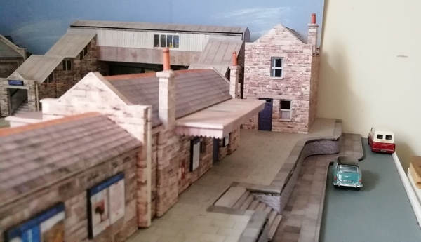
So, we have the Terminus more-or-less complete - Station Buildings and Footbridge, the pavement and roadway. Now I just need a few more bits to add as and when I get time to build them up, namely starter signals, station nameboards, some Platform Lights and then a few passengers milling around. There's also the working traffic lights to fit controlling the station road exit and the hoardings to put up as well as a background at the end of the station.
I still need some ballasting plus some coaling muck to darken the ballast and uncoupling ramps (still working on ideas for this). And then there's some fencing and scenery work to do to the side of Platform 1 leading down to the footbridge over the tunnel entrance. Still plenty to do on the station.
So that's where I'm up to.
I've also got plans on building….. But that's for another report!
In the meantime….. Back to the drawing board with card and glue in hand!
Posted

Full Member
Doug
'You may share the labours of the great, but you will not share the spoil…' Aesop's Fables
"Beer is proof that God loves us and wants us to be happy" - Benjamin Franklin
In the land of the slap-dash and implausible, mediocrity is king
"Beer is proof that God loves us and wants us to be happy" - Benjamin Franklin
In the land of the slap-dash and implausible, mediocrity is king
Posted
Full Member
I'm sure you could make a better job than I did - but it was a first try with them and I think they turned out reasonable (viewed from a distance!).
I'm always on the lookout for interesting plants and such-like as I'm out walking. This Rubella plant in our front garden took my eye earlier this year and I was quite pleased at the early results. Perhaps with next year's cropping I'll try to make something more - some differing colourations of foliage to be added.
Cheers
Dave
Posted
Full Member
It's still only on the laptop though but it appears to run through its simulation ok - only when I get the signals, etc. installed onto the layout and run a few trains through will I know for certain what amendments I might need to make.
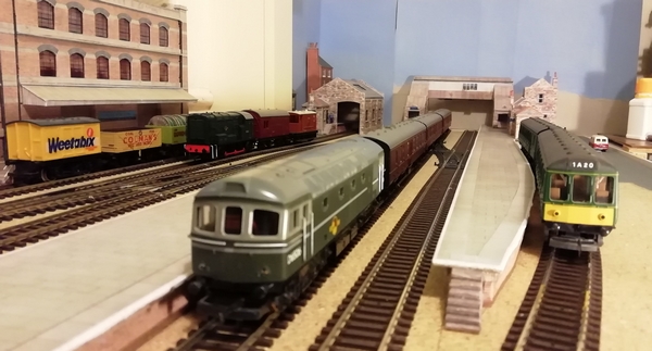
As the old grey matter has got a little frazzled by it, I've also been doing work elsewhere on the layout. What little work I've done is to add some lighting and a backscene to the Terminus.
What a difference adding a few lights into various buildings can make to how a layout appears - even during a daytime running session. Even better with the room lights turned down. Brings it all more to life.
Over the past week or so I've been adding a few small LEDs into the various buildings on and around the Terminus, even retro-fitting them into a previously built Metcalfe set of terraced houses (PO221). The back panel needed cutting off and a few strips of internal "wall" inserted to make a couple of rooms rather than the whole thing being totally empty. Another Metcalfe kit that had a retro-lighting makeover was the corner pub (part of a set of three models, R205). The bar area can now be well lit - all it needs is a few tables and some customers! And connecting to its supply rail - and adding power to some of the houses also.
Fortunately, the other station buildings fared sufficiently well enough after being removed from the old layout that their lights still worked - if only I had made a note of the resistor values I used for some of them! I found a few values, but with a bit of experimentation and the taking of current measurements, I soon had it all back to (more or less) normal. It never amazes me how essential paperwork such as this can mysteriously disappear over time.
Just a couple more lights to add to light the backscene (some street light simulation) and also some platform lights and once in place we'll see how it goes from there. In the meantime…..
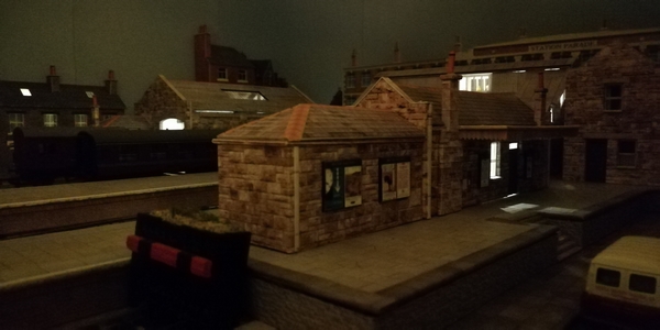
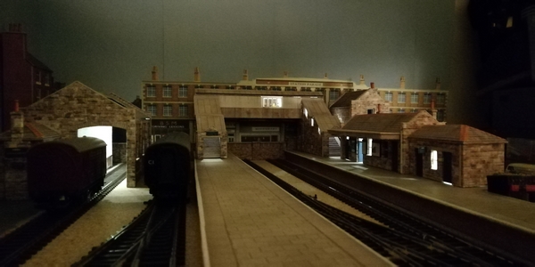
These images are still in the early stages from a construction viewpoint and are a few quick snaps on the phone taken in a rather dark environment (to show the lighting). When I get a bit more done and a bit more time, I'll drag the trusty camera out and see what sort of image that will produce.
1 guest and 0 members have just viewed this.