John Street - BR(E) - 1960
Posted

Full Member
My second bash at model railway-ing
At long last, after a few weeks of doing very little (it was "summer" after all - what little there was of it!), the Terminus area has now had all its track laid and the track wiring completed and things are starting to look something like the plans. A few more minor changes to the layout have been made….. but that's another story. The turntable still has yet to be finally fitted and connected - that's a 'to do' for another day. A couple of buildings, taken from the old layout, have been added (generally for effect) but will form the basis of where they will be placed when the platforms get constructed.
The hidden sidings area has been completed together with "end-of-line" warning sensors and a strip of foam rubber across the track ends in case of over-runs - of which there will no doubt be quite a few! The turnout solenoids here have yet to be connected as are the frog connections. But it's getting there.
On the subject of solenoids - nothing has yet been wired to some form of activation switching. This I am still looking into. A bit late in the day you may query - but on the old layout I used a "pen and stud" method of switching but there were times when sparks were drawn from those studs on making (or is it breaking) contact and on that I'm none too keen to replicate. Possibly all that would be needed is a diode or two across the coils. I have seen a form of electronic switching using low voltage level switching and MOSFETs (with built-in diode protection) and it is this I am looking into at the moment. I just need to build up a prototype to drive a couple of solenoids and see how it performs. More on that later.
There's still quite a fair amount of wiring yet to be finished - DCC droppers mostly around the main trackwork. At the moment I'm largely relying on the good hearted nature of the rail joiners to provide connectivity in many places. All the track sections will have its own DCC feed at some stage in the near future. At the moment I'm happy to be able to run a train or two around the layout and now that the terminus is connected, I can run the full circuit, out and back again. The first train out will be the Black 5 pulling a rake of 3-coaches (plus a truck), currently sitting on Platform 2 in the photo above - departing very shortly.
Then there's the 12 volt supplies to the building lighting circuits and a 5 volt supply to the turnout switches for mimic and, later, signal logic stuff. All yet to be built. But we're getting there…….
More news as and when,
Cheers
Dave

Posted
Full Member
The CDU currently in use is one of many very similar designs easily found on the web which gives a quick burst of power and then, effectively dies - putting only around 50mA into the coil until the coil is removed from the circuit, i.e. disconnected either via the (momentary) switch or contact. So, the spark I have been seeing is probably being made when the connection is initially made and not the removal of the power and the back-emf from the coil. Or maybe I was too fast to remove the stud and it was the back-emf I've been seeing.
Over the weekend I tried out a new scheme using a pair of MOSFETs to do the actual switching of the solenoid coils. The MOSFETs are driven by a low power 12volt supply via a simple ON-ON switch (nothing momentary of this type of switch) putting a pulse onto the Gate of the MOSFET. After blowing (destroying) one device, probably due to too high a Gate voltage being applied I finally got it going and it appears to work well. All mounted onto a small piece of stripboard measuring approx 25mm x 12mm (one inch x half inch in old money!) for the one turnout motor (Peco PL-10WE).
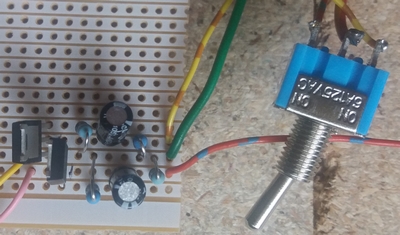
I can't claim originality for the circuit - it came from a design by Ken Stapleton, easily found on the web.
All I need to do now is to duplicate it across all 26 solenoids, mount it all on one piece of stripboard and then mount the switches (and indicator LEDs) onto a (yet to be built) mimic board.
Other than that, I've finally been able to run a few trains around the layout - the Black 5 was the first out, quickly followed by the DMU (strange how I missed operating the trains
 ). The problem at the moment is I need relatively long arms to reach over and manually switch the turnouts as required!
Next job, after finishing the solenoid driver switching and mimic panel will be the turntable so I can turn around the arriving locos.
So much to do; but at least now that October has arrived, we're back into the modeling season into the run-up to the "C" word in a few months, and then summer to look forward to.
Cheers for now
Dave
Posted
Full Member
The layout itself is up and running - which is good. A couple of decent running sessions have been had - if only to get a feel for it all.
The next stage is to get it electrically sorted. The connectivity of it all! A bit overwhelming at this stage.
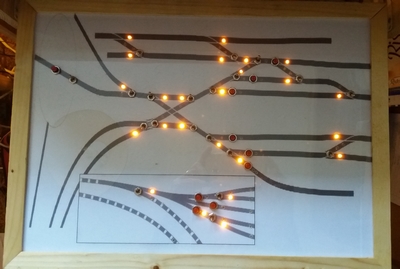
The point solenoids are connected to a tag strip - and they operate ok using the old pen and stud method. These terminations will next connect to the MOSFET driver board and thence to the mimic panel where the points will be controlled by their respective switches as per the picture in the previous post. The CDU has been modified with a smaller reservoir capacitor plus the addition of a 12volt regulator for the MOSFET gate drive power.
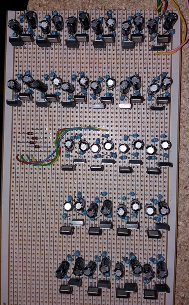
Above, the photo shows the completed MOSFET driver board for the solenoids. All it needs now is the wiring to be added to the switches on the mimic board and to the solenoids track-side - almost 100 separate wires! Also showing is the diode matrix for the 3-way points set in the hidden area (hopefully it'll work on the input rather than on the output as on the previous layout). As an aside, the photo was supposed to be displayed sideways on but Windows, in its superiority, decided not to rotate it after I rotated and saved it back it in the edit suite. One of the little idiosyncrasies I love about Windows

The building of the mimic panel seems to be the stumbling block at the moment. A backing-print of the layout is (more-or-less) prepared and this will be stuck onto a piece of hardboard as a rear panel and then spray varnished over to protect the inks. The various switches and LEDs will be fitted onto/through this following the appropriate drilling. Then a sheet of clear perspex will cover the LEDs and have holes created for the switch levers to poke through. Getting a method of mounting the mimic panel is a bit of an issue - but it's being worked on and should be ready when I can get some wood cut to length to support it all; some strips have already been cut and grooved with one still to cut (and one to re-cut due to it being cut 3mm short).
Then there needs to be some further thought on all the wires that will need to go between the mimic board, the MOSFET driver board and the layout itself (and the logic side of it all at a later date). So long as it doesn't end up like the rat's nest as on the previous layout then I'll be happy!
That's it for tonight - a long walk tomorrow with the local walking group - around 12miles or thereabouts, so no train stuff till at least Monday.
TTFN
Dave
Posted
Full Member
Back to railway matters…..
The next stage of John Street is on its way to being been completed - the construction of, what some might consider, a small and possibly insignificant part of any layout - the mimic board. There's still a long way to go, but it is getting there, albeit slowly.
I had this idea of wanting to have a mimic board that was of a decent size so that the switches and indicators for around the Terminus area didn't appear to be cramped together and that it could be put out of the way when the layout wasn't actually in use. I arrived at the idea of making a grooved wooden mitred frame with a hardboard backing board to hold the switches and the LEDs together with a clear perspex cover to protect the 'diagram' all inset into the grooves in the framework and the whole thing put onto drawer runners held underneath the terminus. The idea took some while to come to fruition with many hours of playing around with various ideas in the back of my mind of how to put it all together. It still ended up with the make-it-up-as-you-go-along principle! (never fails).
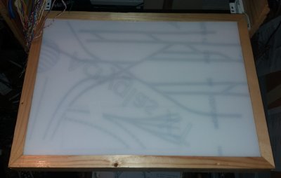
The photo shows the frame on its runners and the image of the terminus (and the hidden sidings underneath) under the perspex cover but without any of the switches and LEDs that will be scattered across it all.
The frame has been given a coat of varnish to give it some protection from any knocks and bangs that might come its way. Under the frame itself has been added a plywood base, partly to protect the wiring and the LED leads under the mimic board, but also to add some additional space at the rear on which to place a PCB or two.
Some may consider all this as a bit of an over-kill for something so simple as a method of switching points and having some form of indication as to which way the points have been thrown - and also with signals repeater LEDs. But, in my mind, quite a lot of time is likely to be spent gazing at this and, therefore, it needs to be relatively pleasing to look at and easy to use. My previous layout had nothing more than an offcut of white uPVC cladding, black marker pen lines and a number of holes drilled into it for the switches, etc. It worked; but was not over-pleasing to the eye and there was far less on that board than there is (or will be) on this one - and the underneath….words can't describe the rat's nest of wires; nothing organized about it at all! Hopefully this board will be better organised.
This photo shows the MOSFET board for the solenoids with some of the wiring added. The CDU is currently in the process of being upgraded to supply a separate 12v line for the MOSFETs - the solenoids run from the full 20+ volts.
A secondary mimic panel has also to be put together - this will be another off-cut of redundant uPVC cladding (I never throw anything away) - but it will only have switches and indicators for the three points, those away from the main terminus area, and a couple of associated signal repeater LEDs. This will be screwed to the layout boarding closer to those points affected.
Right, back to the grind. Let's see what other disasters are heading out way!!!
Posted
Full Member
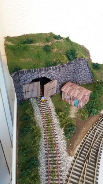
From my original idea posted in item #39 back in August of having a short length of disused track disappearing into the wide blue (or should that be, green) yonder, I have now developed this into some form of reality. The line now veers off to the left and disappears into a blocked off tunnel mouth.
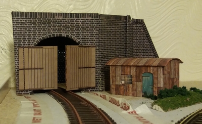
This is the basis of the idea - a tunnel mouth and some retaining walls with the line closed off with some large doors. The lineside hut, to the left, is a camouflaged points motor which had to be mounted above the baseboard due to a lack of space below (at least I think that was the theory at the time!). The track has been rusted over and some preparation made for the ballast to be added which will stop it from spreading too far from the track.
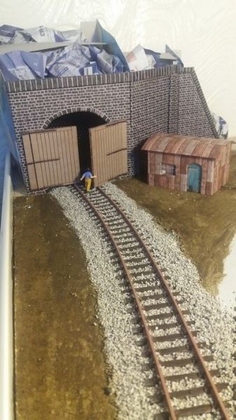
It's my first go at ballasting and I don't think too bad a job has been made of it - unless someone would care to advise otherwise. Some Woodland Scenics Raw Umber painted over the baseboard ready for the addition of some "greenery".
Not for from finished, this little corner of the layout. There's even a 'gate keeper' trying to shut the tunnel doors. All that's left now is to add the "hillside" above the tunnel mouth and away to the right and maybe a couple more lineside workers to add.
Feeling relatively pleased with it so far. Constructive criticism is always welcomed.
So it's still work in progress; some static grass may get added when I get hold of a suitable static machine (without spending a fortune for one! i.e. DIY).
Next ….. finish the hillside - or back to the soldering?
Posted

Site staff
Ed
Posted
Legacy Member
reg
Posted

Site staff
http://brian-lambert.co.uk/Electrical.html#One describes one method for solenoids or useRegarding Dave,s requirement to switch points and have an indication by way of say an LED or signal on track. I suppose one would need a passing contact switch ,which at the end of the throw on each direction makes a normal switch contact . Does anyone know of such a switch ? of all the manufactures out there maybe someone would come up with that.
point position indication
Ron
NCE DCC ; 00 scale UK outline.
NCE DCC ; 00 scale UK outline.
Posted
Legacy Member
reg
Posted
Site staff
Ron
NCE DCC ; 00 scale UK outline.
NCE DCC ; 00 scale UK outline.
Posted
Full Member
Thanks for joining in the discussion on the mimic points indicators. Not sure if this will help Sparky's question though, but for what it's worth…..
The method I use is with Peco points (either electrofrog and/or insulfrog) with PL15 (double) switches added - one switch is used for switching the 'frog', the other switch for the mimic indicators. It also makes use of a single wire back from the point indicator switch to the mimic board.
I use a positive supply (either +12v or +5v, which ever is your preference) to one side of the switch and ground (0v) to the other side. The switch blade then feeds back to the mimic board and goes to the centre of two LEDs wired in series between the positive supply and ground. Then depending on which way the switch is made, one of the LEDs will light. Not forgetting of course the current limiting resistors in series with each of the LEDs, as per the quick diagram below:
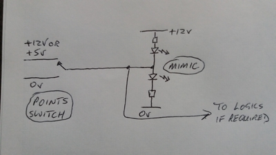
This diagram shows the point switch where the positive supply feeds to the top of the lower LED, lighting this one. Had the switch being in the lower half, to the 0v line, the top LED would be lit. Incidentally, it would be essential to use the same voltage throughout, i.e. to the point switch AND to the LEDs (not made clear on the diagram - too quickly drawn up!).
I have now decided to use a +5v supply to one side of the switch as the switch blade also feeds nicely into some logic circuitry (using PICAXE chips) as it gives me a logic "1" or "0" to allow some determination as to whether I get a green "OFF" signal depending on whether an exit route is fully setup, or not. But this has no effect on the wiring to the mimic LEDs - it's just an added complication that I've added over and above the basic mimic indicators.
The method I use for switching the points solenoids is taken from Ken Stapleton's 751D diagram, see previous post #42 and http://www3.sympatico.ca/kstapleton3/751D.HTM. The reason behind this was, on my previous layout, I was using the stud and probe method of switching the points and I was dismayed at all-to-often having sparks at the point of contact between the stud and the probe at the moment of contact. I think that this sort of spark would be generated irrespective of the type of (momentary) mechanical switch in use; hence I opted for the solid state method and a low voltage (+12v), low current simple single-throw single-pole changeover switch (not "momentary" type) and which now doesn't have the sparking issue. I measured the current at the switch and it was very, very low (milliamps) as opposed to the relatively high current drawn by the solenoid itself - something in the order of 2amps or more. The MOSFETs being used are rated at 7amps continuous (31A peak) and are more than capable of switching the sort of current required by the solenoids.
Yes, it's more expensive, and yes, it's more complex but I'm happier with it and without the sparks, which I am sure would, over time, cause problems with the mechanical switches themselves. My posts #42 and #43 shows my stripboard layout for a multiple of these solenoid switch circuits, (25 of them).
But I think I digress from the initial query regarding the mimic indicators.
I hope this helps. My view is there's no "right" or "wrong" way to do things, just so long as they work and they work for you.
Dave
 Last edit: by Dave C
Posted
Legacy Member
Looks like an answer there . Thanks again.
reg
Posted
Full Member
In view that I want to get hold of some (flexible-ish) wire mesh before I do the scenery stuff, I've decided to have a go at finishing the wiring. Problem is, there's that much junk built up under the layout, it is now difficult to get to anything where I need to work - and there's very little space to move the 'junk' elsewhere in the room.
It makes sense to finish the wiring though as it will make the layout operation activities that much easier; instead of manually changing the point directions by hand, it'll be done at the flick of a switch with an immediate view of the track direction. The switch will give me an indication of direction, but an LED is far easier to see and spot an error in route selection/setup. As mentioned previously, the switches are simple change-over (not momentary) switches (SPST).
Part of the wiring has been done in the past day or so, in so far as the wiring of the frogs in the hidden sidings. I still can't switch to any of those tracks yet as the solenoids have yet to be wired. Should have done this months ago! But life is never that simple or straight forward and I'm easily sidetracked to something else.
Note to Self - "must keep focused on the job in hand".
As this will probably be my last post before Christmas, allow me to wish everyone a Happy Christmas and a hope that 2018 will be kind to us all.
Dave
Posted
Full Member
I didn't take a lot of notice of it (never in all reality did I think I would). I digressed and got the Turntable up and running and connected to the layout (it's been sitting in situ and unconnected for months - prepared but disconnected from power and the rest of the layout). It took a number of attempts to get it to run properly - firstly the motor wouldn't grab the turntable spindle, so it kept spinning while the turntable didn't; then in an effort to tighten the grub screws further, their threads stripped, so new screws were pressed into service; then the index disk seemed to be distorted and fouling the sensor (probably because of the screw heads distorting the disk), so that needs to be sorted. All probably down to my ham-fisted working methods rather than any issues with the motor/indexing kit. So it's still lying in situ and still in a non-working state.
It won't beat me! For what it has cost - it WILL become fully working.
Anyway, I wanted to get this update finished before the end of the month - squeezed in (almost) at the last minute!
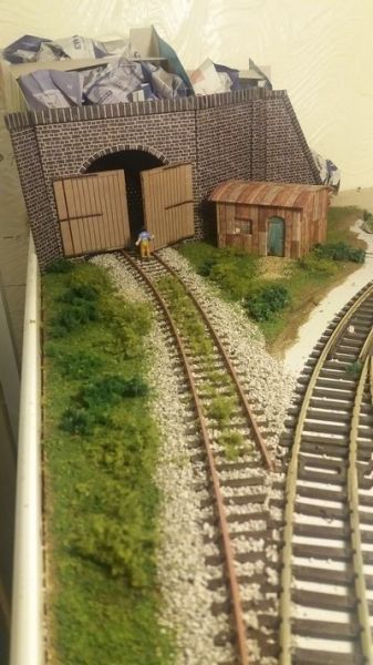
Also, I've completed the disused track and tunnel entrance with some hillside and greenery added. Starting to look something like it ought to be. Will still need to add some sort of back-scene at a later date and possibly some small trees to blend the back-scene to the hillside. All these distractions to keep me sane and away from the many, many wires that have had to be soldered to LEDs, switches and to the MOSFET solenoid driver board.
Back once again to the mimic board and electronics - that part of the layout I was trying to keep focused on to be completed after my last post.
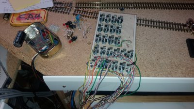
It has now (at last) been progressed somewhat - point switches and LEDs fitted and most of the wiring added. Another slight change of plan (again) - after many versions of the wiring/connection scheme (I like to keep things flexible in my mind!). Planning? What planning? - and this now allows the fitting of the turntable buttons and hidden-section-sidings end-of-line LEDs to be added. It's up and working, but with some stuff that still needs to be added - such as for wiring to the signal indicators for the platforms.

The above picture shows the MOSFET board complete with its myriad of wires - 49 in and 50 out. The missing input wire is part of the diode switching for the 3-way points. I'm sure the cabling could have been neater, but it works. It may get tidied up and tie-wrapped later. One side point about the MOSFET design from Ken Stapleton is that if using relatively heavy duty wires feeding the solenoids is not your thing, then this design (in singular form) can be fitted very close to the solenoid and only thin wires are needed from the switching location to the MOSFETs as the inputs run only a few milliamps at +12 volts - it's the output from the MOSFETs that is in the order of several amps. In my case, I've lumped all the MOSFETs on one board relatively central to the terminus area where the majority of the points are (thus defeating the idea of not wanting heavy duty cables running everywhere!).
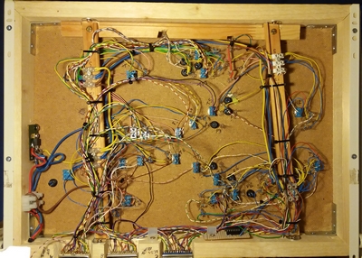
…… And the underside with the 25-way connectors feeding the MOSFETs and the direction LEDs, etc.
Now that this board has been finished to an operational level, there's the secondary mimic board that controls a few other points elsewhere to be built on the layout and away from the Terminus - in comparison, a quick and easy job.
All-in-all, quite a progressive few weeks since my last post. Even had the chance to have a couple of running sessions - and that's what it's all about. Made a lot easier now that the mimic board is mostly finished - no more reaching across to manually change the points. Luxury!
Posted
Full Member
Now that both mimic boards are fully (well, mostly) up and running, making life so much easier to run the layout, the time came to give the soldering iron a welcome rest.
As there was a huge gaping hole leading under the terminus entrance where three tracks disappear, I thought it time to build the tunnel entrance. But not simply just a tunnel entrance (there's a couple of other, more conventional, tunnel entrances to build elsewhere on the layout) but a footbridge over the tracks in front of the scenic stuff and the upper (Terminus) tracks. Essentially it's still a tunnel entrance but with a bit of a difference.
Using one part of the Peco Girder Bridge Sides pack (LK-10) it fronted a piece of hardboard (which fitted the girder inner slot nicely) with a 6ft stone wall (RailwayScenics) to the rear and the steps at one end taken from the Scalescenes Footbridge kit (R007) bringing the level up to the upper baseboard. I've yet to decide what to do at the other end; no doubt it will become simply a normal footpath across the scenery with, possibly, a few concrete slabs coming away from the footbridge.
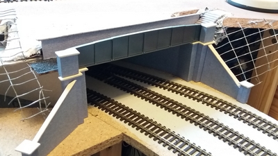
More scenery is to to be added at a later date to cover the wire hillside formers - early days yet on the scenery building.
I now need to find the soldering iron again and get the signalling installed. One colour light signal has been added at the Halt exit - fitted to the baseboard but not yet wired to anything. Also a small Theatre Display has been built (and tested on the breadboard) using a 4511 BCD chip that will be driven from a PICAXE chip which will control access to the Terminus from the UP line. Since the following photo was taken, it's all been given a coat of grey paint so it should look the part a little better. I have yet to build the signal upon which it will be mounted - but one step at a time! If anyone should be interested in the 4511 chip and the display itself……just ask.

The Display is, admittedly, not truly prototypical being a slanting display; but my fingers are not into fibre optics and the associated gubbins required to make it all work in a neat and small enough package to sit atop a colour light signal. So a small 0.3", 8mm high, 7-segment display was found on-line, purchased and utilised.
The PICAXE chip has had its program written and tested/simulated (in theory it works); the chip has been bought - I just need the two pulling together and some more wires adding from the pointwork in the Terminus area so that the correct platform number can be displayed. One day when the other bits of software have been written for the Terminus itself then the two chips will tend to run hand-in-hand - along with a couple of other chips along the way that need to interact with what's in front of the signal(s) they control.
And thoughts on getting the turntable up and running…… Moving swiftly on!
More on all these as and when I get my mojo back into gear. It's seized up with the cold weather!
Cheers for now.
Dave
Posted
Full Member
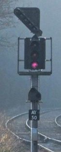
The Associated Position Light being that item above the number board and below the signal itself.
From: Dartmoor railway.
Can I find any to suit? No way.
I've tried to make one (I need many more than one though) out of black plastic (from old food trays) with a couple of very small SMD LEDs sandwiched between two layers of the plastic. Not entirely successful but with a bit more practice, buckets of patience and a brain-storm along the way it might do the trick. The idea was by taking measurements from a Ground Position Signal (Eckon ES24) - just the top part - and make something up from that. But with the sizes being down to a few millimetres each way (6.5mm high, 6.5mm max width) …. my fingers (and eyes) are struggling. And there seems to be nothing available on the web. Unless someone knows different. Maybe this is where a 3D printer would come in handy, but I can't justify the cost of one of those things just for this.
But I'll keep trying the scratchbuild idea - and then there will be the logic and programming to go along with controlling it all - it's part written but the mind keeps going numb and the need for silence to concentrate becoming ever more a pre-cursor to thinking logically about anything. Must be an age thing!
So there we go. Another small step forward with the Home signal completed and a long way to go yet on the Terminus signalling. But we're getting there.
Posted

Full Member
Posted
Full Member
Regarding your shunt signal, now known as a Position thingy - for reasons just a bit beyond me, I obtained mine for the approach to Woodside Station from Absolute Aspects. Matt does do post mounted shunt signals as well as ground signals, I just ordered the whole thing, including platform indicator. I know you're into building your own, but you could try AA, see if you can get just the shunt signal (for post mounting). More on the AA signal, see
http://yourmodelrailway.net/view_topic.php?id=14114&forum_id=74
Cofion
Keith
Do I have a plan? Na, if I did I'd spend most of my time trying to remember where I put it.
Posted
Full Member
I've not been that active on the railway front over the past few weeks or so, this mostly due to my mojo definitely having gone AWOL - I think it decided to go to warmer climes - shame it didn't take me with it! Anyway, apart from one or two health issues now being put aside, which haven't helped, I think things are starting to get back into some sort of wanting to get on and actually do something. No posts for over a month, then two within the space of a couple of days. But when there's something to celebrate…..
First off has been the completion of the Home Signal and Platform Indicator for the Terminus approach; it's now complete with a second coat of paint on the Indicator display and has been mounted onto the baseboard a short distance from the UP/DOWN cross-over. The picture shows the signal/display against a temporary background - the background will be where the turntable should be but which is currently a big hole in the baseboard waiting for the index disk being correctly aligned to pass through the sensor.
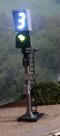
The display, as previewed on the previous/above post, is now fully installed atop the Home signal; the cables have been run back to the control circuit board (a PICAXE chip) together with indicator (monitor) feeds from the points within the Terminus so that the controlling chip will know exactly which platform the approaching train will arrive into and will make the correct display on the Indicator Board.
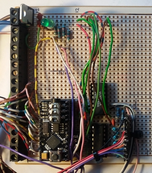
The board shows the brains of the signal control - the PICAXE 28X2 (bottom left) - together with the 4511B display driver chip (to its right) and the ULN2003a (above that) that drives the red/green LEDs and which in time to come also drive the mimic indicators. It's still a bit of work-in-progress but it does indicate which platform is set and that the approach is 'safe' over the cross-over. The pcb itself is a little untidy, but it works and does the job. Hopefully there will be space for the terminus chips as well.
Not much else has been achieved on the layout itself - much time has been taken up getting my head straight to think "programming", not just for this chip but also the chip controlling the Terminus exit and ensuring an OFF signal is given only to the appropriate platform and only when the exit route is correctly set. The programming is only in BASIC; nothing involved like C++ or anything complex (never got my head around C of any variety - my mindset still goes back to the days of the ZX Spectrum and it's variety of BASIC) - it should be fairly straight forward to program, but when the head is a bit muffled, nothing is straight forward or easy.
Hopefully, I can now start to concentrate further on the Terminus signalling and then getting the platforms built (initially starting at the small Halt station).
Dave
Posted
Full Member
I've had a look at the AA website and can find nothing related to post-mounted 'position indicators' such that I'm looking at making. The only signals of this sort are the Ground Mounted Signals that sit on the trackside - unless, as you say, you buy and entire signal complete with theatre box and the position signal.
They've got some interesting signalling kit - especially the direction indicator board which you have made excellent use of at your Woodside approaches.
Shame, as I had my hopes raised. Thanks anyway for mentioning their website to me. I will email them and see if they can supply just the position indicator bit that I'm looking for.
Dave
1 guest and 0 members have just viewed this.