John Street - BR(E) - 1960
Posted
Full Member
My second bash at model railway-ing
Oh boy! Has it ever been hot! Not a lot of activity in the Train Room over the past couple of months as a result. At last, it's forecast to cool down, albeit with some much needed rain.One small project I managed to get to grips with, was a cut-down version of the Scalescenes (R019) row of cottages. As designed and published, it was for a row of four con-joined cottages. But I didn't have that much room on one part of the layout - so I decided to convert it down to a two-cottage set. Thank you Inkscape for allowing me to copy and print only those selected parts required and not whole pages full of other unnecessary "clutter". And that program was a bit of a learning curve in itself! But we got there in the end.

I know, there are no chimneys fitted - or barge boards. But there is some internal lighting; so you can't have everything. The chimneys are always the last to be fitted and the first to be knocked off - so I just wait until I'm ready to put it onto the layout along with other items in that area (reduces the risk of accidental damage - me being a bit 'ham fisted' at times).
Now I just need to build a few more of these cottages - and to probably make up the "proper", as designed, kit of four cottages, if space permits in the small village scene I have in my mind. If I seem a little uncertain about available space it's because I tend to make it up as I go along and muddle through what goes where and what seems to look better. At least the track plan is fixed down, so there's not much chance of playing around with that!

Posted
Full Member
Anyone who reads my posts - or shall we call them "ramblings" - I do tend to 'go on' quite a bit - no comments please! And as a result of my single grey cell sometimes being overloaded, I do like to make copious notes on how everything is constructed and, more especially, wired up - mostly in case I need to fault find or to reconstruct something that wasn't quite straight forward.
As a result of many, many pages of 'stuff', for which most of the time when I need to find something I needed to spend ages searching through for not just for the right piece of paper before finding the right information, I decided, while the weather was so very hot and sitting quiet was the best way to cope with it, was to make up a mini pseudo web site with links to here, there and everywhere. So every piece of information is now a couple of clicks away via links within each "page".
It was all basically hand-coded using an old copy of MS Office's Front Page as a kind of syntax checker in case I missed an occasional "<" or ">" around a link - of which I did miss many - typos in my case! Or a simple text editor, such as Notepad, could be used. It's all done in (simple, straight forward) HTML5. Nothing fancy, nothing complex; but - even if I say so myself - it looks quite good. Just a load of writing with a few "<a href=….>" and "<img src=…..>" commands for the links to other pages or images and bits of it put into "tables" so that the writing appears to wrap around the images. Getting some of the syntax wrong can lead to some quite "interesting" outputs!

Sample page showing how the Home Signal and its Theatre Display was constructed, wired up and connected from its processor to the signal itself.
The next step was to copy all the files and numerous pictures over to the mobile phone and using a simple (free) web server app allowing me to view the information in the same manner on there and I don't need to have the laptop up and running all the time. As yet, some of it doesn't get displayed quite correctly, but I'm still working on it. One minor issue - now it's getting a bit more complex - I found was that the mobile phone ought to have its IP address fixed (made static) so that the local "web site" can be found quickly (this is done in the router set-ups under Local Network - might be called something else on your router - DHCP?). Without this, the phone's IP address can change, especially if the phone is powered off overnight, as mine is and finding the correct IP every time can be a nuisance. The phone IP address can be found under Settings / About / Status Information.
Posted
Full Member
 Last edit: by Phil.c
Phil
Posted
Full Member

Posted
Full Member
Phil
Posted
Full Member
I seem to be going through a phase of starting something and then not getting it finished before moving onto something different.
On the last post, I had built one the Scalescenes Cottages (R019). Then another got started, same as that photographed earlier. It almost made it to the completed stage except for the addition of some lighting needing to be added. Then I thought I would move onto building a walled section to hide the gap between the upper level from the hidden lower section. That got very well under way and is, much like the cottages, almost complete - lighting was fitted into one of the units through the brick walling before I moved onto the next section of that walling block - the road tunnel and in the next wall section a set of steps leading from the road up to the top level - that took some work putting that together; a total of about 60+ pieces of card glued together to form the staircase. Anyway, that did get completed (now there's a surprise!) - well almost completed!.
All I need now is a section of baseboard to fill a hole between the Longmeadow station and the walled unit. Trying to find a piece of 12mm chipboard (same as everywhere else) of suitable size has proven difficult to say the least. I've ended up with 12mm plywood - a huge 4 x 2mtr sheet of the stuff. I just need the time to cut it more to the size needed (0.7 x 0.6mtr). Most of the remainder will have other uses elsewhere away from the railway. So all is not lost or overspent!
For once I do have a plan of where I'm going with this next stage of building up the village of Longmeadow. I usually just "wing it" in the hope it'll look right at the end of the day.
So, at this stage, there are no new photographs to add.
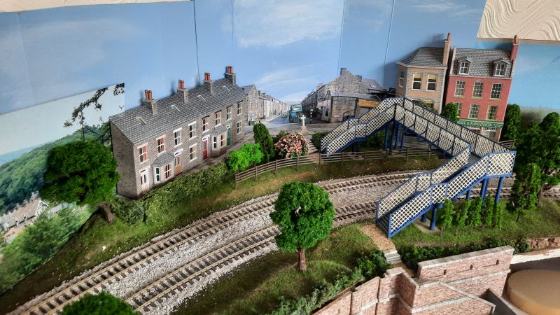
Oh, all right then. Just a quick snapshot of where the walled section is right now - in it's not in its complete state. It still needs finishing off once the piece of plywood has been cut and fitted under the wall section to match up with the road level. So at this stage it's just a preview of how it might look once it all gets joined up and fitted into place.

Work in progress…… You can see the gap I'm needing to block/hide at the right of the photo.
Back to the workbench. Hopefully, now that the weather is turning more inclement with the onset of autumn and then into winter (despite the unusually warm temperatures at the moment), I might get some of these outstanding jobs finished and I might even get to run a train or two (miracles do happen!).
Posted
Full Member
It's a power supply unit. The old power pack was starting to show signs of insufficient available power to be considered stable. So, an old computer power supply, modified to give some protection against any short circuits, has been pressed into service - a bit "Heath Robinson" I'll admit; but it works. Each wire coming out of the PSU has been given an in-line blade fuse - 'cos there's an awful lot of available power in these things, enough to melt the cable and probably do a lot more damage as well (perhaps) should a short circuit occur. This way, I'm limiting any damage that might be caused.
There are a number of articles around the web on how to get these things to work outside of a computer - like how to get it to power-up (by shorting the PS-ON pin to ground) and giving the PSU a "load" to start with (in this case a 4R7 10W resistor between the 5v rail and 0v, bolted to the inside of the case near the fan for heat dissipation as well as a pair of ceramic cased 3R3 resistors (at the back of the fuse block) connected between the 3.3v rail and 0v to give that extra bit of "load").

I can now have a number of separately fused +5v rails and same again for +12v. There's a 3.3v rail as well, though not in use for the layout (yet). Good and stable at 5.1v and 12.07v. The red LED is for mains power on (+5VSB) and the green LED is for the PSU actually turned by a small switch behind the fuse box (connects PS-ON to ground) - or simply connected direct to 0v, if that's your wish.
So that has side-tracked me a little.
Other jobs still in process - changing a couple of colour light signals back to working semaphore signals (almost there) - the building of the rear wall (from the last post - waiting for some landscaping at the back of it - almost there) - and building some more buildings for Longmeadow village (a long way to go!). Thank goodness winter is coming along rather rapidly now.
Posted
Full Member
They're a pair of Ratio 486 LNER Lattice Post Signals (recycled from my old layout). So, even though I've not had the pleasure of building them at this time, there's been the fun of writing the program to operate them and they seem to work without any modification to the main layout signals control program - which was a relief. They've been made to operate by using a pair of small SG90 servo motors and some stiff(-ish) wire linked through the board to the operating levers. The processor doing the work is a much underworked/under-utilised 18M2 PICAXE. For more information on the control programs take a look at https://yourmodelrailway.net/view_topic.php?id=16438&forum_id=7&page=1 - this covers all sorts of signal and some layout automation stuff based around the PICAXE processors.
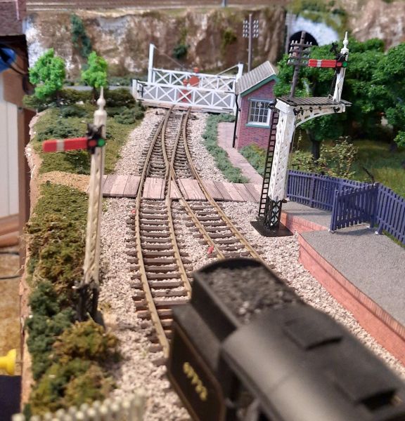
The sequence of events is that when a train is detected as being on approach, the level crossing gates open, the signal is raised into the OFF position. This state remains until the train has reached a sensor just beyond the level crossing. At this time the signal drops to the ON position (complete with a "bounce") and once the train has fully passed that same sensor, the gates will close.
Then there was the required add-on piece of board adjacent to the walled section also mentioned in the previous post; this has now been sourced, cut and fits nicely, so that can soon be semi-fixed in place and populated with something, as yet, not fully decided.
The walled section has gotten a stage closer to being fitted - a bit more scenic work still needs to be finished on the top level at the back of it and then that can be secured in place. That will be pencilled in for doing later this week.
All in all, a decent few weeks of rather slow progress. But (just like British Rail used to say back in the old days) "we're getting there". Rome wasn't built in a day - and neither was this layout!
Posted
Full Member
After a slight mishap from a dangling piece of clothing (but it's been soooo cold, bbbrrrrr), the siding starter signal suffered a catastrophic malfunction - the top 3/4 of the lattice support broke away from its remaining bottom 1/4, rendering it somewhat un-fixable. It was in a bit of a sorry state after being stored for a few years anyway, but nevertheless I tried to fix it and it looked a complete 'dog's dinner', so to speak. Shame really, as I had just completed getting it setup with the servo and arm positioning.
Somewhat gutted, yet fortunately for me, I had a spare 486 kit and after a few hours work, a replacement signal was built and pressed into service after salvaging the signal arm and head structure from the damaged item. Another hour or so and the servo and arm had again been aligned to provide the correct arm positioning.
All systems are (essentially) "go" again. But it taught me a lesson about leaning over the layout with dangling clothing!
Now all I need to do is to sort the control program out and fix a strange error that causes the level crossing gates to close before a train has had the chance to start to reverse in to it. This aspect of layout operation has never been tried and fully tested. So now I have to try to figure out the programming again and get it sorted. Surely it can't be 'that' difficult to sort - probably one command in the wrong place.
Posted
Full Member
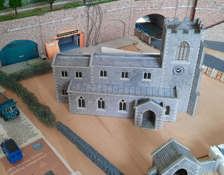
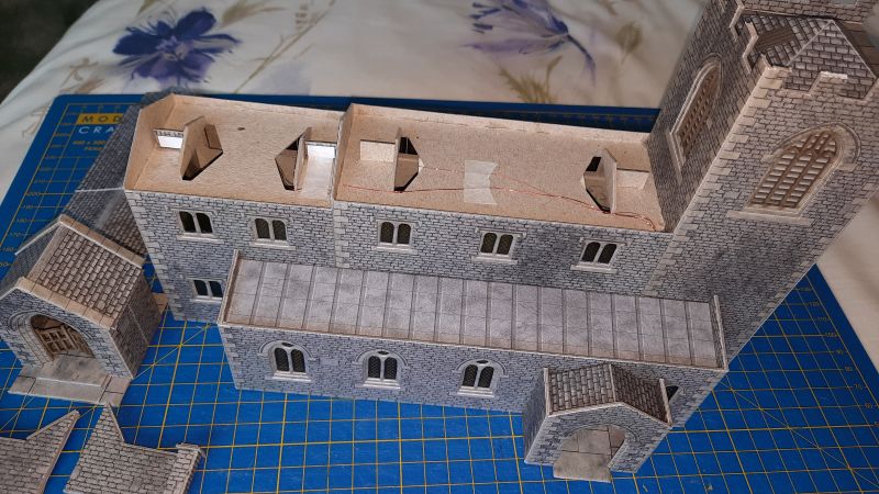
Over the past month or so, I've been busy constructing the Metcalfe Parish Church (PO225). Quite a build in many ways. Took a bit longer than I had expected, mostly because I wanted to add some internal lighting as the construction went along - but health issues also got in the way which didn't help. But we're about back on track and firing on at most three of the four cylinders again. There's still the siting of the Church and its associated churchyard and grave stones to be completed yet. The Church is looking good though - photos to follow when things get nearer to completion.
Also, as the semaphore signals (as mentioned in the previous posts) are working well now that the software has been modified, I thought I would add another two further back on the layout, replacing colour light signals - that's another Ratio kit needed to be purchased! So I now have a mix of colour light signals:
on the John Street terminus platforms and at the terminus Home (entrance) position, also at the top of the passing loop.
And then there'll be (soon) 2 new semaphore signals at the first and second signal positions prior to those at Longmeadow station where they are already in place and working; so that will make 4 working semaphore signals up and running.
So there'll be a bit more (automated) animation going on - I still need to build the kits up and make further modifications to the software that runs the signalling - and they will (hopefully) have small LEDs to light up the aspects (that's the plan); I've had a try out with one signal lamp unit and it seems to have worked ok - very fiddly though, my ageing fingers were not designed for such small things!
If only there were more hours in a day, it would help and I might get something completed!
Posted
Full Member
If nothing else, the top corner of the layout has had some more work done on it and is just about complete - all it needs now is some people dotted around to bring it more to life.
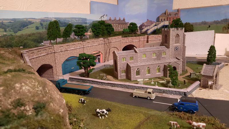
Also, the church is finally in position now that the add-in and removable piece of board has been cut and fitted. The church has yet to be fixed down, and the surrounding greenery/churchyard and its boundary walling needs to be sorted. As promised, a photo is attached showing the overall area together with the temporary and very much simulated boundary walling, hedging and new roadway.
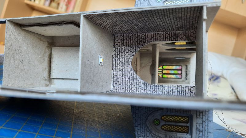
The next 3 photos show the Church internal lighting using small SMD LEDs. The windows have also been painted using permanent ink pens - although they don't really show up too well here.

The new semaphore signals are still in the work phase on the bench. Getting the distant signal's black chevrons on yellow (white to the rear) painted has proven more difficult than I had expected. A few emails later and a better solution came forth - obtaining some replacement signal arms from MSE (https://www.wizardmodels.ltd) and some waterslides from Hall Royd Junction (http://www.hall-royd-junction.co.uk/Products/Signal_Transfers/index.html). The "lamps" have been very carefully chiselled out to insert a miniature SMD LED so that the signal aspects will show the relative aspect for night-time running (I like lighting on the layout!). So once these parts arrive, work can (hopefully) progress here - photos at a later date.
In the meanwhile….
Printouts for the Scalescenes Terraced Houses (R022a) have been printed and some more printouts are needed for a few more Scalescenes Cottages (R019) to populate the village scene next to Longmeadow station. Plenty to do in the coming weeks/months(/years?).
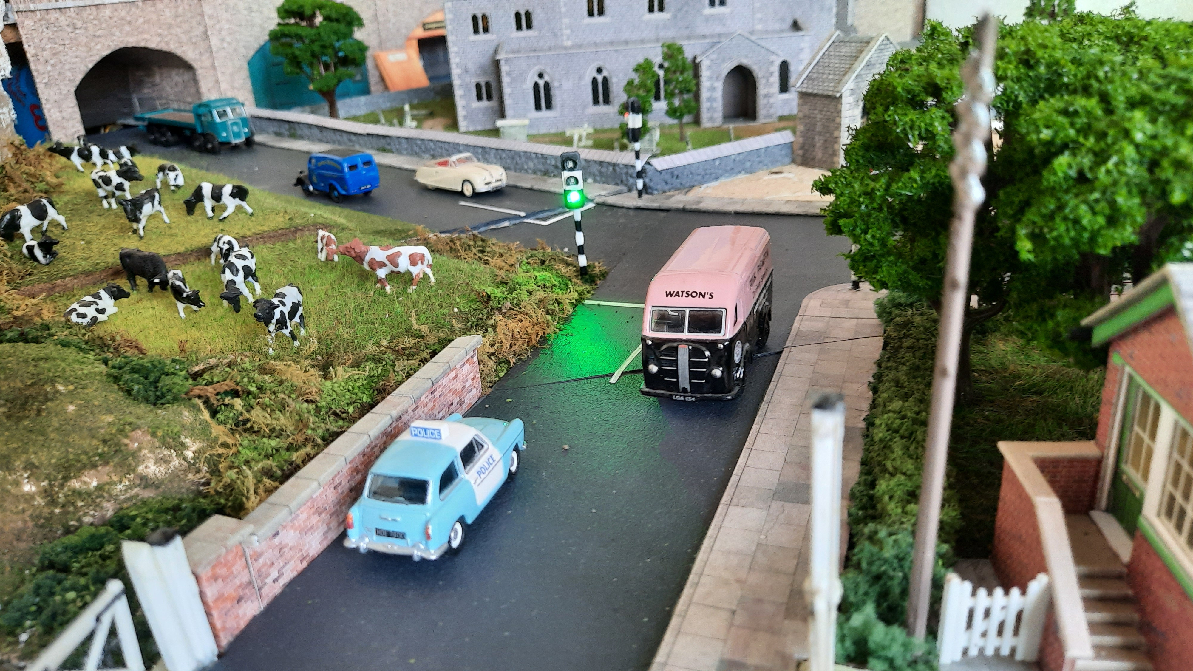
The next small project is an idea for working road traffic lights now that the baseboard has been extended (the central "hole" filled with and the Church in place) so these can be added shortly. The road has been marked out (with newspaper) disappearing into the left side road tunnel - road painting to be added as and when time permits.
A design has already been published for operating just one traffic signal head - see https://electronicsclub.info/docs/trafficlight.pdf. This uses a 555 timer chip and a 4017 (divide by 10) counter ic. I did make one of these - it worked very well, but only had the single head, so it was a little limited in where it could be placed. It's been installed near the Terminus (where only one signal head is visible anyway). My brain cell couldn't work out how to add an opposing/joining signal and to maintain the correct light phasing - although I'm sure it can be achieved. Hence the idea of this PICAXE chip design. I believe in the KISS principle.
Again, like the signalling (and other stuff on the layout) this design is created using a PICAXE processor - a 14M2. The traffic light heads complete with posts, were bought from the well-known auction site and shipped half-way across the globe; this included everything needed for the lights themselves - and ready made. The only other work needed was to add the black and white stripes to the mounting posts (lengths of heatshrink tubing over-painted) as typical of the 1950's/early 1060's and also similar stripes painted on the heads themselves. Again, photos to follow when fitted.
The program itself is very simple with just a few 'turn on, turn off' commands to control the LEDs and numerous pauses between the light changes. The timings of the "yellow" aspect can be tuned to suit - the regulations (from what limited information has been found) are when going from the red, the yellow is also lit for two seconds before going to green, and going from green to red, the yellow is lit for three seconds. The length of time each road has a green light is entirely user defined, dependant upon the (non-)moving amount of traffic.
The small pcb for the semaphore signals was added to and has made use of the +5v feed to the other processors on it - this feeds the LEDs and this new processor. The LEDs have a common anode (+) and each cathode (-) is taken to ground via a 330R (or thereabouts) limiting resistor (one for each LED) and into a port on the processor. Nice and easy and should do the job very nicely.
If only the traffic could be made to move. I've seen an idea or two but I think it not entirely practicable here. But who knows in the future.
So, I've not exactly been sitting on my thumbs - there has been some work going on!
Posted

Full Member
Posted
Full Member
As far as fitting LEDs into the church is concerned, I used a mix of a string of 3 LEDs and a string of 2. The way to get a good balance of light output between a mix such as this on one building is to measure the current passing through each string and balance them to be the same. Mine were checked at around 5mA as I didn't want too bright a light in such as the church.
There are a few apps around that will do the calculations for you - for example, for my string of 2 white LEDs from a 12v supply and using a 1k resistor, the current would be 4.8mA and for a string of 3 same LEDs, same current, a resistor of 250 ohms would give the same current and the same brightness as the other string of 2 - with the standard resistor value of 270 ohms the current would be 4.4mA and be a little less bright. Bearing in mind that the resistor values can change depending on the LED colour and how bright you need the light. I rarely allow the current through any LED to over 10mA - plenty bright enough for me.
But I agree, the work that can go into fitting LEDs (and other electrical trickery) against the general value to the observer doesn't really compare. But try running the layout in the dark and it all suddenly springs to life. Makes a whole world of difference - to me at any rate.
Quite a bit of scenic work has been going on this morning on the area surrounding the church - looking much better than in the photo in the last post with the start of adding the churchyard grass and pathways, etc. and also the makings of the road adjacent to it. More photos to come later.
Posted
Full Member
At last we have lights inside the church - even though they seem a little bright (maybe an additional resistor is needed to dim them slightly) - together with a suitable graveyard and a boundary wall.
The adjacent road and path is now almost complete, getting prepared for the installation of the traffic lights. The black wire in the background on the work units is for the lighting inside the small garage. I'll get round to connecting it up shortly.
Strange - do one job and another related idea comes to mind that could be added. And so it goes on….and on…..
Planning? Yea right!
Posted
Full Member
They've been on the back burner for quite some while - but there were other jobs that were needed finishing before I could "plant" them and get them working, such as the fill-in/removable baseboard with its church and also a completed painting of the road that goes over this piece of board and onto the main board.
As mentioned in an above post, the project uses a PICAXE 14M2 processor and some traffic lights from the far east - the black and white bands (typical of the 1950's/early 60's) were added post purchase, those on the main posts were painted onto heatshrink tubing and then (heat)shrunk once on the posts. The posts needed to be sunk into the baseboard to give the correct height of the head units.
Back now to the new semaphore signals…..
Posted

Site staff

Posted

Full Member
Cheers,
Claus
www.flickr.com/photos/ellef/
Claus
www.flickr.com/photos/ellef/
Full Member
There's been quite a lot happening, albeit quite slowly - well, very slowly if truth be told!
One idea that came to me the other night (literally while trying to get to sleep) was regarding the Level Crossing and trains that stop at the station immediately before it.
There's a level crossing near to me with an adjacent station that really annoys me. The barriers come down and we wait….and wait. Then a train arrives at the platform, stops, discharges its passengers, etc. And then moves off over the crossing - there's no (railway) signals here. I know the automated crossings these days must be closed for - what is it - 25 seconds at full line speed. All the time we're waiting for the barriers to lift. Annoying but I guess in this day and age of Health and Safety linked to automation, etc…..
I recall in the mid '50s at my then local (SR) station, there was many a time the level crossing would remain open to traffic while a train arrived in the platform. Only when it was about ready to depart, was the crossing gates opened for it to pass through. Gone are those days of the signalman on site who kept a watchful eye on things and operated signals, points, gates, etc. accordingly.
With this in mind and my idea of automating as much as possible (I just run the trains - the signals, etc. look after themselves), I decided to try to implement a similar arrangement whereby known trains that would stop at this particular station would have the gates kept closed against it for a short period of time - all protected by a Stop signal of course. And me watching what I was doing.
A couple of Hall Effect switch sensors buried under the track - one to disable the gates opening and the other to re-enable the gates once the train had arrived in the platform - and a magnet under each of these "stopping" trains should do the trick and with only a couple of additional lines in the programming, the job should be a good 'un. Now to get it implemented.
All I need to remember now is to actually stop these particular trains rather than just let them run straight through. There's no power-sectioning to ensure track power isolation - no room for it. Ooops! New gates, anyone?
Posted
Full Member
Basically, the test circuit comprises a +5v supply to pin1 of the 3144 together with a 270R resistor to the anode of the LED. The cathode then goes to the output on pin3 - ground being to pin2. Always check the pinouts for the device you are using - the A3144 is not the only Hall Effect switch available.
The magnet used here is the NdFeB (Neodymium) Magnet Disc, N35M, 5mm x 5mm dia., part no.505891 from various suppliers, which gives a good strong magnetic pull in such a small component. Other magnet types/sizes are available which may be better/stronger/smaller - or maybe not - but these magnets have been in my spares box for a few years and, at last, they can come out and get used.
When connected 'in-circuit' to the PICAXE (or whatever) processor is being used (Arduino?), a 10k pull-up resistor is needed between the switch output (pin3)/processor input and the +5v rail and a 0.01uF capacitor between the output and ground/0v. The A3144 is good for use with supplies between +4.5v and +24v but, if you use it with a processor, it must not exceed the more normal +5v. The sensing parameter does not appear to change with increasing the supply voltage (according to the datasheet).
In use, the magnet is placed under the coach or loco, painted black if it is obviously visible, and relatively close to the track without it fouling on any in-track sundries such as AWS ramps, etc. with the HE switch located between sleepers and at about the same height such that they are not too obvious to the more casual viewer. Avoid anything that will cover the face of the HE switch as this will reduce the effective switching point range.
Using the magnets under certain coaches/locos, can potentially allow certain trains to be treated differently from other trains - such as on my layout, which is relatively automated, to change when the level crossing gates are opened depending on a "stopping train" as opposed to an express, "through" train. I know, it's a novelty feature, but is based upon how things were at my local SR station back in the late 50s whereby a train that stopped in the station invariably had the gates kept closed against it until it was about due to depart. This kept the busy road traffic flowing more than under the current line rules.
A little experimentation later with the test circuit (above) and with the magnet described and the A3411E, the bottom surface of the magnet was found to work with a 10mm air gap to the surface of the 3144. The magnet was fitted centrally underneath a truck with the 3144 at baseboard level (level with the sleeper base) - the air gap was 8mm and the magnet was essentially out of sight. :D
Remember to have the SOUTH pole of the magnet towards the marked surface of the 3144. The north pole will not operate the switch. Unfortunately, these magnets come unmarked, so the test circuit is a must have to check which end is which - or trial and error.
Now to fit it for real under the required rolling stock and to update the software to recognise the switch is in place and active.
1 guest and 0 members have just viewed this.