John Street - BR(E) - 1960
Posted

Full Member
My second bash at model railway-ing
The "how to" is way beyond the capabilities of my remaining 7 live brain cells Dave but the "what it does" is brilliant ! How I wish I understood electronics - they're such clever blighters - and invisible too. ;-)Did just painting the LEDs solve the bleed problem or have you added something inside ?
It's a great looking signal and, as most modellers haven't the faintest when it comes to signalling, you can run it any colour you like - as long as it's red, green or white …..
'Petermac

Posted
Full Member
I think, given the current level of activity within the cranium upstairs, I must surely be well down into single figure brain cells by now. So long as these few keep working, that'll do for me.
Nothing has been added within the signal head other than some black acrylic paint around the edges of the LEDs, plus a fair bit more paint generally slapped around within the head itself (much like before actually). I guess the difference is the paint that actually got applied to the LEDs themselves has done the job. The resistors are external within the wiring loom back to the control board (there ain't no room for them - or owt else - inside the head).
Incidentally, I could have used a yellow LED replacing the whites - that would have been just as valid on this signal, but I'm not sure under what circumstances it would be used - I'd need to have a look around t'web to find that out. But this does the job for me for the placing and the period being modelled _ late 50's/early 60s.
Posted
Full Member
Posted
Full Member
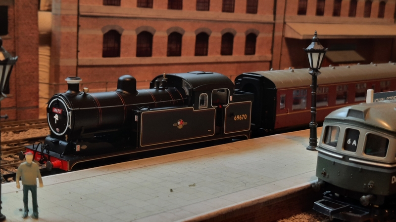
It fits in beautifully with the time period of 1960 (or very thereabouts). GER/LNER N7 #69670 was built local to me here in Doncaster at the end of January 1926, it finally got withdrawn from service at the end of September 1960. So it sits very nicely for me. Still needs a DCC decoder fitting and a bit of (DC) running in….. but this will come in the fullness of time.
Not overly keen on the red running number on the boiler, but this is a minor issue and nothing that detracts from the model itself. Thanks to Oxford Diecast for producing this model. Nice to have a "small" loco instead of the larger Pacifics (et.al.) for a change.
Edit:
This loco was withdrawn from service end of September 1961 (not 1960) - so that fits my more general timescale slightly better! - and was built by Robert Stephenson & Co., I think, of Newcastle (not in Doncaster). Some were built in Doncaster, but not this numbering.
 Last edit: by Dave C
Posted
Full Member
I too have the N7 - sound fitted. The white decoration on the smokebox door and around the chimney is a bit incongruous for a kettle but those can easily be rectified by some judicious weathering using tips from Gwiwer !!
'Petermac
Posted
Full Member
Disaster!
At one set of (facing) points it decided to take the (non-existent) middle option of trying to make a third exit rather than take the inner curve of the two exits - this on a curved double radius set of Set Track points. It would appear to negotiate the pointwork ok at a snail's-pace, but give it some speed and, no chance, off it comes time and again. Not happy with this situation - a new loco unable to negotiate a set of points at speed. A good examination of the running over the pointwork gave no hint as to why it should derail. it just seemed to jump.
My initial thoughts of "why" it should derail is the combination of the smaller wheel diameter of the N7 together with the spacing between the driving wheels and the natural gap in this Set Track pointwork at the frog (ST244). I might be wrong but it's a fair guess. Either way, these points are "history!".
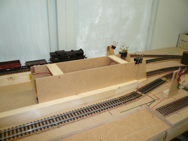
The problem with this set of points is that it is buried under the exit throat of the terminus with very little room to see or to manoeuvre a pair of hands and to shine some illumination. As luck would have it I had an unused Streamline code 100 double curved points and whilst the curvatures are different I thought I might be able to make it fit with a little jigging of the adjoining trackwork either side of the point.
To prove the pointwork & that the loco would negotiate it ok, a few lengths of track were temporarily attached and the loco run at full speed through the pointwork, hoping as I did so, it would remain "on track" - which it did, thankfully.
As mentioned, being buried under the terminus with a headroom of only around 75mm replacing the offending point was no easy task. As well as having to replace some of the adjoining trackwork, some of which had also been part-ballasted as it entered the underground area, I needed to wet, loosen and scrape out that ballast and then clean up the baseboard before I could cut back some of the old track and then fit some new track to meet the points. Yet, having got the offending point out and into the daylight, I can see nothing obviously wrong with it. So that set of points will be condemned to the scrap box or maybe a possible trailing configuration in future, if ever I have need for more trackwork.
Location of the offending point in the process of being replaced together with the newly cut-away area of scenery at the left (where the lamp is currently living!).
Then there was the issue of adding a new location for the operating solenoid - and that now needed to be above the baseboard due to a lack of space directly underneath and that it also needed to be across the other side of a 3-way point with no chance of an operating wire being put underneath those tracks. And that involved the operating rod from the solenoid to go through the baseboard, across about 150mm and back up through the baseboard to operate the point. No easy task to complete. The point itself needed to be glued down as there was not enough headroom to knock in track pins.
And now there are a couple of across-the-track sensors to re-jig just adjacent to this set of points - I'll get those sorted in the next few days.
All because I bought a new loco - how silly of me!
Having said that, I do have another loco that has, on the odd occasion, done much the same thing when the leading pony truck flips out of the track - but I had largely put that down to the very minimal weight of that truck. The Oxford model certainly has no lack-of-weight issues being diecast, quite heavy (in comparison to many models from other [perhaps more mainstream] manufacturers) and no lightweight pony truck to go a-wandering.
Thankfully all is running good again. Now, back to where I was before all this malarkey started - wherever that was - it seems a long time ago; I'll need to fire up the old grey cell again and see if it can recall anything I might have been working on!
Until the next time……
Posted
Full Member
My DC "running in" track uses set-track curves - I assemble and dsismantle it whenever I need to use it. I'm not sure what radius the curves are but the N7 simply would not accept them.
The problem appeared to be associated with the first two driving wheel axles - the second axle wanted to follow the track but that threw the first off.
I have yet to try it on my layout - currently, much of it is covered in "bits" from what is a building site so I can't use it.
I'm slightly worried about 2 areas - the first is a rather tight corner which will prove to be nigh on impossible to relay and the second is, as with you, a curved crossover formed by 2 Peco curved points.
It is becoming evident with modern models that your track laying has to be as near perfect as you can make it and tight curves are a no-no.
I hope I don't have to face your problems - relaying the areas of concern on mine would create some real headaches ……………. :hmm
'Petermac
Posted

Full Member
I used Set Track curved points in the cartridge approach tracks on my old Yarslow layout and found them to be problematic for certain engines. My solution was to ensure that the locos only ran in one direction - the points gave trouble depending on left or right hand - weird!
When reading your post about the N7, I read “Set Track curved point†and feared that they would be a problem
Barry
Shed dweller, Softie Southerner and Meglomaniac
Posted
Full Member
All the track used on the layout is code 100 Streamline & Flexitrack - only two sets of points are Set Track, the one I've had problems with and the other (it's sister) being used as a trailing set, which so far have proven to be OK.
Given the length of the wheelbase on the driving wheels, I might have expected the centre axle to not have flanges and to be just a straight tyre. Whether that would overcome the issues we, and no doubt others, are having I'm not sure. A couple of "old" diesel locos I have do have the middle axle of the bogie as a flat/non-flanged set.
I do find it strange that Oxford haven't made mention of a minimum track radius or a comment regarding some Set Track components. Some manufacturers do indicate a minimum 2nd radius curve, so why no warning (that I've yet to see) from Oxford?
We live and learn.
Dave
Posted
Full Member
My old layout used a mix of 3rd, 2nd and even some short 1st radius curves in the storage area and they presented no problem for even the 8-coupled engines. However, they presented big resistance when I was trying to use 20-wagon freights and 6-coach passenger trains through the reverse curve. The picture below shows the curve in the foreground - the short curve was 1st radius. These tight radii were not the issue. it was always the facing curved point just off picture to the right.
Barry
Shed dweller, Softie Southerner and Meglomaniac
Posted

Full Member
Edit by Sol as photo is copyright
This is the website so just cursor down.
Disused Stations: Bembridge Station
Staying on the thread Kevin.
Posted

Site staff
Edit by Sol
Kevin did not know how to fix it so I found the website & put the link in.
Ron
NCE DCC ; 00 scale UK outline.
NCE DCC ; 00 scale UK outline.
Posted
Full Member
It would be a great idea for an addition for your (or anyone else's) layout if a short loco is in use on that section. Be interesting to see the methodology of building and operating it. Hopefully, it would be relatively close to the operating position such that it could be easily operated by hand and a few gear wheels.
Regrettably my turntable is way across the other side of the layout and there's no way it could be easily or repeatably operated by hand, not even with masses of wires draped across everything to make it turn and align.
If you make the decision to create such an addition, do advise the how you built it and the method used to operate it. I'd love to see it.
Cheers
Dave
Posted
Full Member
Staying on the thread Kevin.
Posted
Full Member
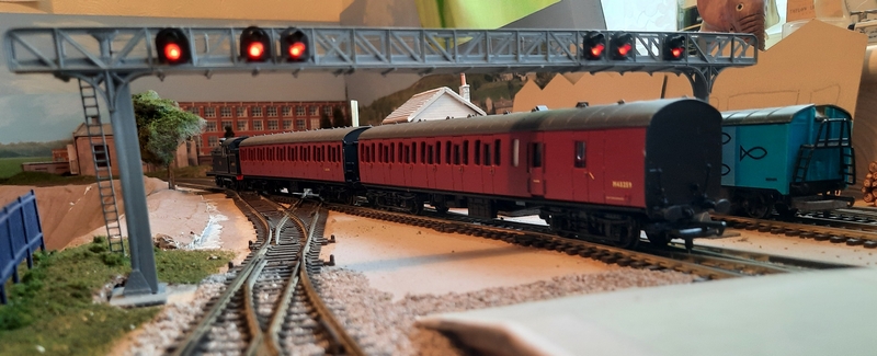
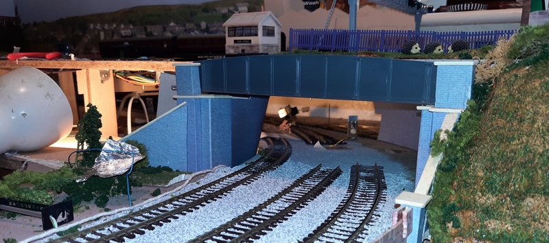
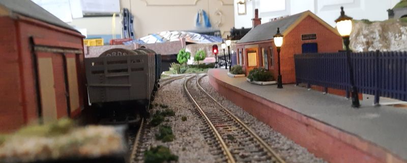
Forgive the foreground scenery to the far left - I still have a lot of scenic work to do around the layout - and this part of it had to be cut-out and removed in order for me to access and replace a set of points that the N7 didn't like running over (see comments above - post #186). There's still a lot of ballasting work to be done also - but we're getting there - slowly.
As can be seen in the photo, the signalling system is now up and working - and that's taken quite some time and a lot of heartache in getting the programming right for it all. It's still not finished, but I now have a basic run-round set of signals controlled by the passing locos, a synchronised level crossing and a degree of recall of which platform was busy and which was empty at power-off so that the Home signal on approach will not display a green aspect to a full platform; likewise I'll not get a green (OFF) signal for a platform with no train present.
I'll be giving a fuller description of the signalling system on my other posting page in due course at https://yourmodelrailway.net/view_topic.php?id=16438&forum_id=7&jump_to=306167#p306167
In the meantime, I shall turn my hand back to some scenery and house building and ballasting and ….. before doing much else to the programming. I may even run some trains (that'll be a novelty for me!).
Posted
Full Member
I've recently been working on a small, but interesting, project - adding some coach lighting to my (very) old Lima 2-car Class 117 DMU set.
Most diesel locos these days have directional lighting, so I thought I would go one step further on this item and add some lighting in the coaches - I know it's all been done before, but not on any of my layouts. To watch trains run round the layout in near-darkness with just directional lights didn't seem to sit right with me - so I thought I would experiment a little on a very old piece of kit. If I damaged it, then, although it might upset me somewhat, it was no real biggie than if I totally messed up a newer, more expensive coach.
The directional lighting (http://www.blackcattech.co.uk ) on this DMU set has been fitted and working well for years with a TCS MC2 (2-function) decoder and as I had some strips of warm white LEDs (in 3-LED sections) lying around I thought I would have a try at fitting some coach lighting.
Originally I had thought of taking a power feed directly off the rail pickups (at the input to the decoder), but this would have meant the addition of 2 more wires crossing between the two coaches in the set (the other 3 being for the directional lighting). Then I thought that as the light functions on the decoder were rated at 100mA for each function then surely I could break into the feed wires to the directional lights and take power off those wires. Just the addition of two extra diodes to effectively isolate the coach lighting from each of the the directional lights and the job would be a good'un - oh, and a series limiting resistor to damp down the brightness of the coach lights - I read that somewhere around 3k3-4k7 should be about right; in the end, I settled for 10K in the feed to each set of LEDs; this value gives a nice, dim yellow light, just as I recall from all those years ago.
A bit of techie stuff now. The decoder supply to the directional light functions is a +12v on the blue wire. The yellow and white wires are the (switched) returns. I take a feed from the blue wire and feed it via a 120ohm resistor into a 220uF capacitor (the negative of which goes to the negative end of the LED strips); the +12v from the 100ohm then goes via the 10k resistor to feed the LEDs. At the far end of the LED strips, other than the negative 220uF capacitor wire, are two 1N4148 diodes - one of which goes to the yellow wire, the other to the white wire. I think the wire colours are pretty much standard these days, but it's always wise to read the documentation that came with the decoder.
In that way, irrespective of the direction of the DMU, lighting is preserved and a degree of anti-flicker is provided by the 220uF and in-rush protection is from the 120ohm resistor.

The last train out for the day, complete with a few late travellers on board, is about to leave from Platform 1.
Very happy with the job and all achieved without the need for adding additional pickups, as will be needed when I tackle the remainder of the coaching fleet. If I ever get that far!
Posted

Full Member
Michael
Posted

Full Member
Posted
Full Member
So this 'joint' signal controlling the exit to the small siding as well as the starter on the main line has come out and been replaced with a pair of single signal posts placed a little further back from the pointwork. A simple change but it took me most of one day to make the changes and get them wired up again. I've been wanting to do that job for a while - so that's got that out of the way at last. More on that (probably) in the next update.
And as if I needed to work on yet another little job while tackling and building up this small Halt station, I thought I would have a go at updating another project that has bugged me for years.
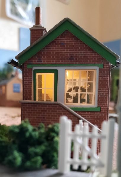
Some years ago, one of the model magazines issued a free small Signal Box kit (from Metcalfe, I think). It was duly built "as is" - without any additions as to interiors. As I say, this has bugged me for ages. So I thought I would see if I could retro-fit some bits into it.
Of course at the time, as per the instructions, the floor was glued down, as was the roof! I mean, who follows instructions to the letter? Well, I did as I was still a bit of a returning newby to the hobby back then. I've learned a few things since then.
Anyway, the floor was cut away as close to the walls as could be (easier than removing the roof) and a new floor created from an off-cut of stock card. Some floor-boarding covering was added and some internal 'gadgetry' (slightly cut-down) added courtesy of LCUT (kit I OO-OO). These parts were duly painted and stuck to the new floor. It's all a bit crowded in there, but it's a small signal box!
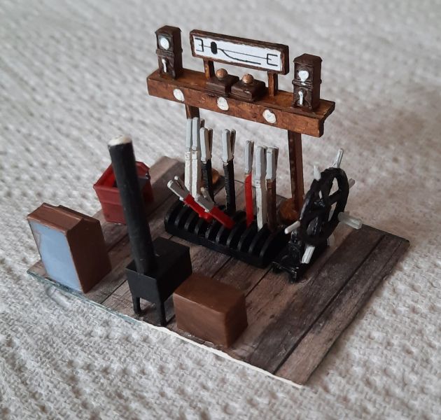
As this Signal Box controls a wooden-gated Level Crossing, I needed to create a "wheel" so that the gates can be opened/closed. That was a bit awkward as there are not that many photographs of this bit of equipment on which to base it, certainly not relative to the GNR/LNER areas.
After a few failed attempts at trying to get something that looked reasonable, I used a length of enamelled copper wire cut and bent (around an AAA battery) to form the 'ring' of the wheel. Inside this was glued a few off-cuts of thin plastic (ex-sprue) to form the spokes and the handles around the 'ring'. All were superglued together, given a mounting bracket and finally painted. I think it looks a fair representation - even if I say so myself. This was mounted on the new floor alongside the other inserts - the whole lot was then placed back inside the 'box' together with someone to pull the levers, etc.. But not until after I had fitted a couple of lights. Nowt much gets fitted these days without some form of lighting added!
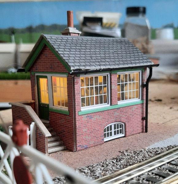
So with the Signal Box now completed, maybe I can get back to the part-completed Halt Station (as yet un-named!). Thinking about it, it's a bit on the long side to be simply described as a "halt". After that, next to do will be the surrounding scenery - not that there's much to do as this section of the layout was built on a relatively narrow width section crossing from the back of the layout to the front (creating a sort-of figure-of-eight) leading from one tunnel, via the station, over the level crossing and into another tunnel.
Posted
Full Member
The two strips of wood that represented the platform have now been replaced with a spare length of chipboard, raised to the correct level and covered with some tarmacadam sheets (Metcalfe M0056) and with brick edgings (Scalescenes R008) and Platform Fencing (Scale Model Scenery LX030) painted in BR(E) Blue - cream painted fencing on the goods platform. The station building is the Staverton GWR Station (Scalescenes R003b). Although it's to a GWR design, it looks the part for my BR(E) layout having had the doors replaced with BR(E) Blue versions together with some suitable hoardings and with LED lighting added - it's a station ticket office building after all, which-ever region's design it is/was.
The short goods siding has also had its platform constructed in the same manner as the main platform, except it has a concrete slab print together with the Staverton Goods Shed at one end.
Also added this past week: A bit of roadway and pavement to the rear of the station, a few trees behind the signal box, a small rough grassed area behind one end of the platform together with a four-wire fence separating it from the pavement and station nameboards. Not to mention the platform lights and a few telegraph poles. I also intend to have an add-on piece of baseboard so that I can have the roadway at the rear of the station to full width, a bit longer in length to meet the road from the level crossing (the junction to have a set of working traffic lights) and a few houses as well. The idea is there - time will make it happen.

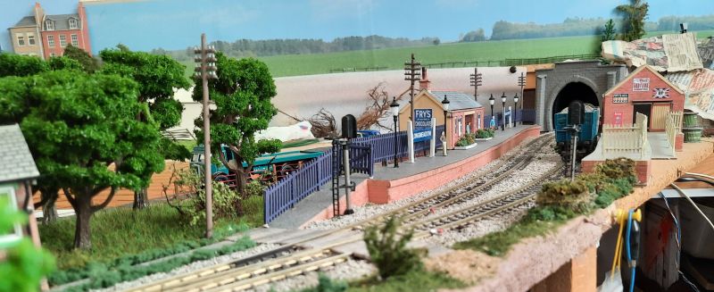
(Forgive the rubbish in the rear of the last two pictures - still very much work-in-progress at the back of the station and behind the tunnel portal)
The exit tunnel, from a hidden area, has had a new portal created from styrofoam in a manner similar to that described by MarklinofSweden (but not as good as his!) and painted an overall dark grey to try to match the aged (mucky!) stonework so often seen in the UK. I still need to finish the portal itself (a bit of extra colouring) and also do some work on the adjacent hillside as well - but they'll all come in time.
I seem to spend more time researching how to make things, and then documenting what I've found, than actually making anything! If ever this hard drive goes down, boy! am I in trouble! And yes, I do keep backups of the data (now and again).
1 guest and 0 members have just viewed this.