John Street - BR(E) - 1960
Posted

Full Member
My second bash at model railway-ing
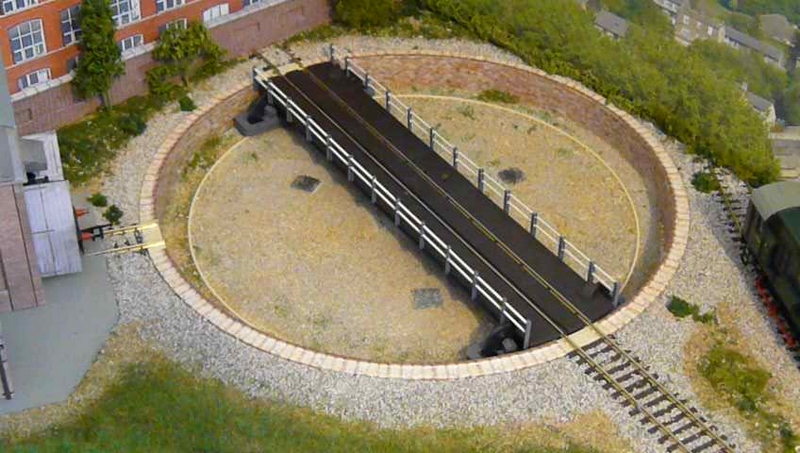
Going back a few weeks to early March, this turntable project of mine is becoming like the "Never Ending Story". First it worked nicely with the 28BYJ-48 stepper motor, then it decided to play up and mis-behave (non-aligning). So that got ditched in favour of a NEMA 17 motor and the Sparkfun Easy Driver board. I tried testing out the motor well away from the turntable with a small test program I cobbled together.No way could I get the stepper to move; no buzz, nothing. I checked the program - that seemed fine. I hooked the 'scope onto the output pin of the processor and nothing. Very weird. I could see the "direction" voltage vary as it was programmed to do as it reverses direction, but no stepper pulses. Then I tried another output port, et voila, pulses. Dodgy processor? No idea; I didn't bother putting the wire back to the original port to try; leave well alone, it's now working! But at least the new motor and the ED board appear to be working well together (so far!). Next up will be getting the program to work and align to tracks once the motor is fitted to the turntable.
The problem with the NEMA 17 motor is that it is far, far heavier (280grams) than the BYJ motor (39grams) and a different, more substantial, method of mounting needed to be found. Progress here was started and everything was "almost" put into place - very much a Heath Robinson contraption! Then disaster! Something slipped, fell and broke the spindle that protrudes from the deck. No way was there any chance of recovering the thing - I tried making a few adjustments; really, I tried. But, in my own mind, I knew it was going to be fruitless. So a new turntable kit needed to be purchased and, essentially, I needed to start again with the deck. The well remains in good fettle, thankfully.
Now, a different method of mounting the motor was devised - still a bit Heath Robinson - with the hope that this would be less likely to end up as another disaster. I don't think the Peco turntable was designed with the thought of adding a sizeable motor to it. I've seen a few designs on the web by enthusiasts, some better than others, and some excruciatingly expensive for what it does. How difficult could it be? Very is my answer!
Just waiting for the post to arrive with the new kit, then I can get started again. Watch this space!

Posted

Full Member

'Petermac
Posted

Full Member
Posted
Full Member
…………….. That's the great about our hobby though, you can move on to something completely different until the desire to have another go takes hold.
Absolutely Dave. That could (and is) a big problem for the butterflies among us …..
Whilst I love the versitility of the hobby, I for one, really do need to focus just a little tighter if I'm ever going to have anything other than "work in progress" .
I also need to stop dreaming about dabbling in electronics - I spend an inordinate amount of time looking up the meaning of all these acronyms you guys use. :???:
'Petermac
Posted
Full Member
Each to our own I always say. Others say that a layout is never finished - that, I think, I could possibly agree with.
This turntable of mine - I appreciate ready motorised units can be bought. I went half-way there with the purchase of an add-on kit. Regrettably it didn't do the job for me - alignment issues. So I decided to go down the DIY route. And, yes, it has probably cost me more overall than if I had bought a complete turntable including a ready fitted motor and indexing.
But the joy of getting your own DIY project to completion and exactly to your spec is incalculable. That to me is the joy of this hobby of ours. The option of DIY or buy off-the-shelf. The choice is there and we can each take the path that suits.
Peter, I've always had an interest in electronics - mostly as a repair engineer working with manufacturers' circuit diagrams. So even I'm learning new things electronics-wise as I try to design projects that suit my needs. Acronyms? I'm none to keen on them, but they do have their place I guess.
In the meantime I'd better get back into the Train Room and progress this thing. If only it wasn't so darned awkward and cramped working under the layout and between the two track levels. I've never had so many episodes of cramp!
Posted

Site staff
https://www.amazon.com/AeroCreeper-Adjustable-Height-Mechanics-Creeper/dp/B079Y1YDLW. :cool wink
Cheers
Matt
Wasnie me, a big boy did it and ran away
"Why did you volunteer ? I didn't Sir, the other three stepped backwards"
"Why did you volunteer ? I didn't Sir, the other three stepped backwards"
Posted
Full Member
Shame there's no clear space on the floor to put it, not even folded. The floor is a tip, a general dumpit site. I never throw anything out (you'll need it tomorrow). One day, once the layout is finished (!), maybe I'll sort it.
I'm sure it will have its uses in more spacious places. Thanks for the link.
Posted
Site staff
And just like you, I've no room under the layout to get it in anyway :roll:
Cheers
Matt
Wasnie me, a big boy did it and ran away
"Why did you volunteer ? I didn't Sir, the other three stepped backwards"
"Why did you volunteer ? I didn't Sir, the other three stepped backwards"
Posted
Full Member
Posted
Full Member
I note that the fully adjustable model doesn't appear to be available here in the UK (not from the quick look around) but I found someone importing it for something over £400. Well out of my price range!
I did spot a few much, much cheaper versions - not height adjustable through - unless a couple of bricks could be employed

Either way, I still ain't got no room swing a cat (apologies to all cal lovers!).
The general tidy up HAS, however started - I put a few loose screws away in a box. Come on! It's a start!
Posted
Site staff
Sorry Dave, Were wandering
Cheers
Matt
Wasnie me, a big boy did it and ran away
"Why did you volunteer ? I didn't Sir, the other three stepped backwards"
"Why did you volunteer ? I didn't Sir, the other three stepped backwards"
Posted
Full Member
At last! I have a turntable that works - and after a bit of re-jigging on the software side through some newly discovered debugging commands - it works pretty darned well, even if I say so myself!
The downside is that it tends to be a bit noisy and a bit juddery, but that is probably partly due to the thin 4mm ply used as part of the motor mounting board and the stepping. I'd like to use a board that is a bit thicker but the nylon spacers I am using are rather ("very") old, of unknown origin and the bolt thread is of an unknown type - certainly not metric - and would need to be a bit longer to accommodate the thicker board. And with bolt options of BA, BSF, BSW, UNF, UNC and no doubt others manufactured over time, I'm not sure what the thread type is, so I have no idea what to look for - maybe our big DIY company across town may be able to assist as and when I can get into their store. I have a feeling the bolt I might need could possibly be 5/32" BSW 1" in length - a lot of uncertainty though. Other than that - the job's a good 'un.
There were a number of tweaks to the program that were needed before I could call it 'job done'. Nothing wrong with the stepper motor - just how the program operated it. Then I thought I would add some acceleration & deceleration to the deck movement. At least it finally got sorted - so now for some detail of the installation.

Stepper motor mounting - note the long nylon spacers and the 4mm ply holding the motor and its bracket. Spot the Hall Effect Sensor (with the blue output wire) against the turntable rim. Also spot the infra red LED on the across-the-(hidden)-track sensor (or rather, half of the sensor pair) to the left.
So, what have we got? As noted before we have the NEMA17 stepper motor - this specific version is rated at 12volts, 400mA per winding with the common 200 steps per revolution of the shaft which equates to 1.8degrees per step. This is driven by the Sparkfun Easy Driver board utilising the Allegro A3967 chip which, in this case and by default, causes the motor to make 1600 steps per revolution (at 1/8 stepping) which equates to 0.225degree per step, but this still gives around a 1.3mm swing of the deck per step. This in turn is driven and controlled from the PICAXE 18M2+. Indexing is taken (at power-up) from searching for the A3144 Hall Effect sensor mounted on the outer rim of the well and is coupled with a small 3mm dia magnet mounted under the turntable deck - all movements are calculated from this initial point. The linkage is a flexible coupling and connects the 5mm dia of the motor spindle to the 4mm spindle from the turntable - it also allows for any slight mis-alignment.

Underside of deck showing the small 3mm magnet mounted on some foam insulation.
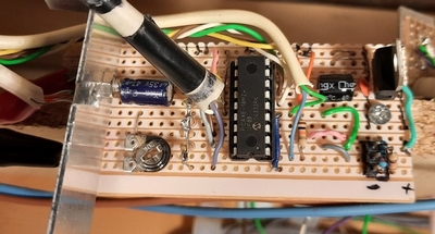
PICAXE board with the 18M2+ microprocessor, a 5v regulator and a couple of other components. The preset resistor allows some adjustment to the speed of the motor.
Only two signals need to be sent to the ED board - DIRection and the STEP pulse that makes the motor move one micro-step per pulse. For the more techy amongst us, the pulse needs to be a minimum of 1uS in width and it is the positive-going part that makes the step happen.
It should be noted that the Allegro chip can, is designed to, and does run quite hot. The motor, on the other hand, appears to remain cool. And given that the Allegro chip and the motor are powered all the time to maintain position the chip may need a little cool air wafting around it. Maybe this will be added at a later time if felt necessary. Or maybe I'll change the Easy Driver board for the Big Easy Driver - basically the same (different Allegro chip) but can drive at 1/16 stepping and should make the deck movement smoother and the final step size smaller. Minor reprogramming would be needed though.
For those who like to watch a turntable in operation, I have uploaded a video of it in operation - all 2min 47 seconds of it. For those who aren't interested, it may be a little boring - sorry - so don't bother looking at it - but the music is ok! Take a look at:
https://youtu.be/RAqhEKJtn5A
This has certainly been an interesting project with quite a steep learning curve regarding stepper motors. So with that project "finally" put to rest, maybe I can get back to the signalling project. Or maybe even run a few trains - now that would be a novelty!
Posted

Full Member
 Last edit: by Passed Driver
Staying on the thread Kevin.
Posted
Full Member
Posted

Full Member
When the time comes to actuate my turntable I am torn between playing with an electric remote setup like yours or a purely mechanical one with a handle through the facia and gearing. I’m leaning toward mechanical but time will tell.
Hope you enjoy running trains.
Cheers
Posted
Full Member
After taking ages to find where I had put it (the train room is like a dump-it site), I thought I would try it out before actually making a suitably sized hole (about 3mm x 6mm) in the baseboard for it and placing it in situ. Oh, what a disappointment - the amount of light bleed from each of the LEDs into the others….. shocking, not really usable. And for the price of these items…..they ain't cheap for such a small item! I had expected something better.
As a try-to-fix the problem, I applied some black acrylic paint around the bases of the LEDs and added some to the spaces between the (standard) LED rounded tops in the base unit and the start of the 'light pipes' or fibre optics that take the light into the outside world in the upper, above track, part of the signal.
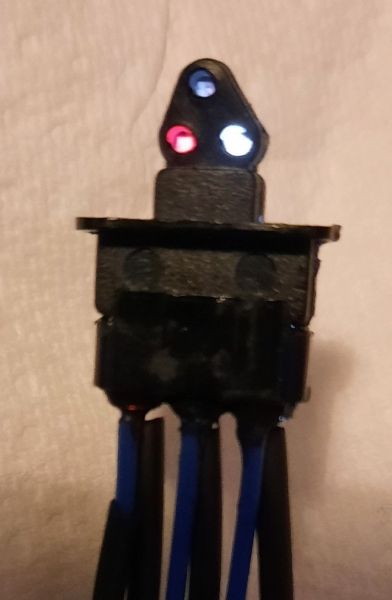
Shunting Signal showing the light bleed from the lower right LED into the (OFF) upper, central LED. This is with a current through the red LED and through the white LED of some 11mA (limiting resistor of 470R from 12v).
It did improve matters, but not to the success I had hoped for - still a little light bleed from the white light. So this is one item I'm not happy about fitting into what would have been a relatively large hole in the baseboard. As it happens, a guy I bought some (non-working two-light) Positioning signals from, and which were modified to hold a pair of SMD LEDs and shine as they ought to, has brought out a three-light Shunting signal, also non-working but should again be easily modified as before. And it will only require a small hole in the baseboard just large enough to pass three very thin wires through (bonus!).
So that's the next order coming up - or maybe buy some Plasticard sheets and cut out the shapes as required (but why put myself through the hassle) - as well as some red SMD LEDs. I'll give an update in a week or two once the bits have arrived and I've found some time to put them together.
Posted
Full Member
After careful examination of the head part, I could see that there was a possibility of putting a thin blade between the two halves and, maybe, just maybe, I could split the head unit apart and have a look-see inside. Let's face it, what have I got to lose - it's not going on the layout 'as is'.
Lo and behold, it came apart quite easily - which did surprise me a little at how easily it split apart. Inside were three clear plastic 'light pipes' to convey the light from the LEDs in the bottom unit up to the 'lamps' in the top. Maybe this is where the bleed is coming from - the sharp bends in the 'pipes'. I know fibre optic cables don't like sharp bends and this is where they spill out. A liberal coating of black acrylic paint (the enamel paint had gone dried out!) over and under them all and generally filled up the otherwise empty spaces, wait for it all to dry, put the two halves back together again, fingers crossed for a decent outcome……
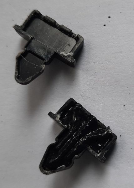
The light pipes, now coated in black paint (it doesn't show up too well in the photo) but it might give an impression of what is inside the head unit - maybe I should have taken a photo pre-paint job (too late now, job done!). After-thoughts are always a wonderful thing, shame they don't come beforehand!
Not sure of the why's or wherefor's but, very little light is now coming out of the white lights and almost nothing from the red. Guess who's not a happy bunny now. But I had nothing to lose by trying it. The ends of the light pipes are clean. Anyway, some problem has arrived on the scene and this part of the project will now be in the scrap bin.
Having said that, I do have some small 0805 SMD LEDs and the white ones will fit nicely in place of the light pipes. So this is the way to go - for now at least. All I need now is some small red SMD LEDs and the job should - I say "should" with hope in my heart - be a good 'un. I'll also be trimming the base part of the top unit so that it will fit flush to the baseboard with only the small hole for the very thin connecting wires to go through.
Ain't life "fun". At least I'll also have some red LEDs for the buffer stops yet to be installed. All is not lost (repeat numerous times until it is believed!).
Watch this space in a couple of weeks.
Posted
Full Member
Having said that, it was a bit more fiddly to fit the red LED than the two white LEDs. Why? I have no idea - they're both the same very small size to solder some very thin enamelled copper wires onto and just as small to get my fumble fingers around to put them in place. I must admit, not all three are 100% correctly aligned relative to the front light openings, but are sufficiently close not to worry too much - a slight adjustment between the limiting resistors compensates for any reduced light produced to the outside world. The size of these 0805 SMD LEDs is a mere 2.05mm x 1.3mm - that's small! And after accidentally burning one out (where'd the limiting resistor go?), I had the "pleasure"(?) of fitting another; such joy!
Getting back to the Eckon kit for a moment. I do very vaguely recall it being a kit that I had built up; but I certainly don't remember building it and there were no spalls left (is that the correct word/spelling?) in the box from which the bits may have been removed - I normally throw nothing away until it's fully complete and installed! Even then I may still hold onto the remaining pieces; they may come in handy for something. So the poor light output most probably was down to me in trimming the light pipes; the light bleed is a different matter - nothing much I could do about that. But that's all history now.
Anyway, wires soldered, red LED put in place, along with the two white LEDs already fitted, and a quick lathering over with oodles of black acrylic paint and a quick test for light bleed. In a totally dark room, there is a slight amount of light bleed, but under normal conditions and at normal LED light levels, it's not a problem. Very pleased with the result.
The GPS is now in place - but with the bottom part that should have gone through a large-ish hole in the baseboard cut off. It now sits nicely on a piece of painted card (as a plinth) with just a relatively small hole in the baseboard to pass the wires through. Then there was the balancing out of the light outputs from the signal head to get each LED closely matched to the other two (the white LEDs seem to be very bright in comparison to the red LED, that is until they were given larger limiting resistors - I ended up using 47k resistors to dim the white LEDs sufficiently using a +12v supply - about 2mA current).
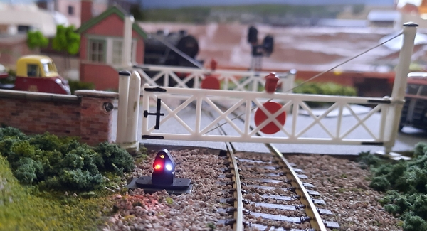
The photo appears to show some light bleed into the top white light, but to the naked eye it is barely visible - certainly in comparison to the other lights.
I'm well pleased with the outcome and it looks the part (at least, in my mind it does).
Edit: Incidentally, the "blob" near the top of the pillar to the left of the gate is the emitter part of an infra-red across-the-track sensor; useful for knowing when the crossing is clear before closing the gates.
Last edit: by Dave C
Posted
Full Member
A bit of careful painting along the sides of each LED as they were fitted as I thought it might also help with what little light bleed remained. It also gave me the opportunity to more carefully align the LEDs to their apertures, this time using superglue to hold them in place - it seemed UHU glue took too long to set and they had moved slightly. I'm still not sure they are 100% (even superglue doesn't give an immediate set - unless fingers are involved of course!), but I wasn't planning on becoming part of the signal head by leaving my fingers in place for too long. so there still might have been some slight shift. Anyway, there is now no bleed at all between the LEDs - success!
I've done some fiddly jobs in my time, but this takes the biscuit; a whole packet of them!
Anyway, the ground positioning signal head is back in its rightful place, as per the photo in my last post, protecting the level crossing gates from any trains wishing to reverse into the siding. As it turns out, the signalling software dictates that the gates will never be closed to trains wishing to reverse back as the gates will automatically open as the train initially approaches the halt station before passing through the station and over the level crossing it waits for the point to change to the siding and then, with the GPS now giving two white lights, reverses back so that the main running track on which it arrived is not blocked for longer than is necessary. Hence, one function of the sensor buried into the pillar on the photo is to sense a train has halted on or just passed the level crossing, ensuring the gates do not close until the train has either continued on its way or has reversed back and cleared both this sensor as well as the main signal sensor on the other side of the level crossing, and into the siding. That's how the software should work. Soon I'll have it installed and tested and fingers crossed….. Then I can get onto something else on the layout - like running trains!
Posted
Full Member
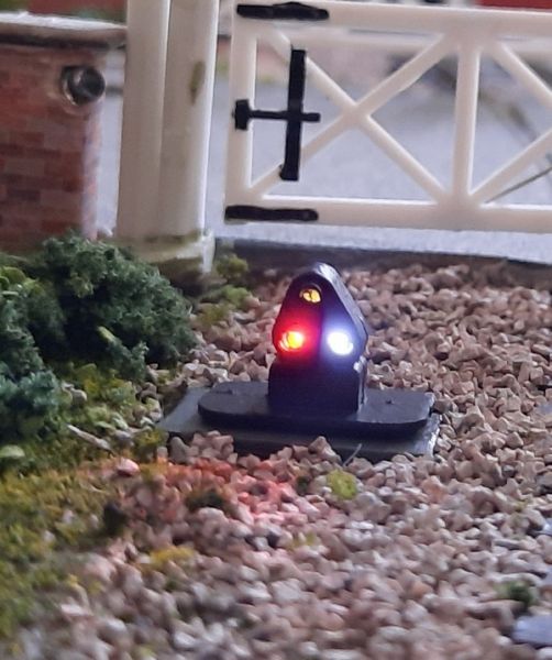
Snipped original image with light bleed into the top white LED position
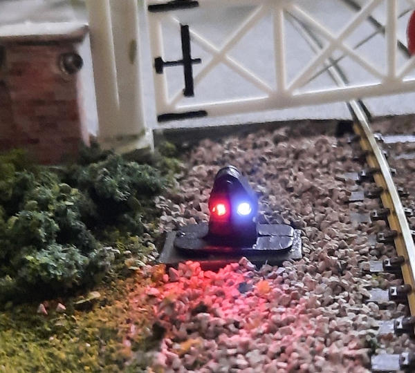
After the rebuild without the light bleed - a vast improvement !
I've tried to get as close to the original camera position as the previous shot. The light outputs have again been balanced fairly closely to each other - 10k to each of the white LEDs (I think the original 47k resistors were dimming the LEDs too much) and 4k7 to the red LED.
Hopefully that's job done now for this little (but troublesome) project.
1 guest and 0 members have just viewed this.