John Street - BR(E) - 1960
Posted

Full Member
My second bash at model railway-ing
At last, the turntable is installed and is up and running.It was a bit of a struggle getting in and under the layout to get the new motor fitted - quite a lot of struggle to be honest with occasional bouts of cramp due to twisting and turning while in the cramped positions.
The method of mounting the stepper motor changed quite a bit from what I had first thought. The stepper motor - the 28BYJ-48 - was first mounted on an off-cut piece of chipboard - the photo doesn't show it too well, but this off-cut with the motor was then screwed under the baseboard that holds the hidden section - a hole had already been drilled through it for the original motor (now removed), as can be seen from the photo below. Doing it this way (on a separate piece of board) allowed a bit of lateral movement to get the alignment between the motor and the turntable spindle right before securely screwing it to the baseboard. The (new) stepper motor then has a couple of 4mm dia. lengths of steel rod and a pair of flexi-couplings to link up with the turntable spindle - these take up any residual misalignment.
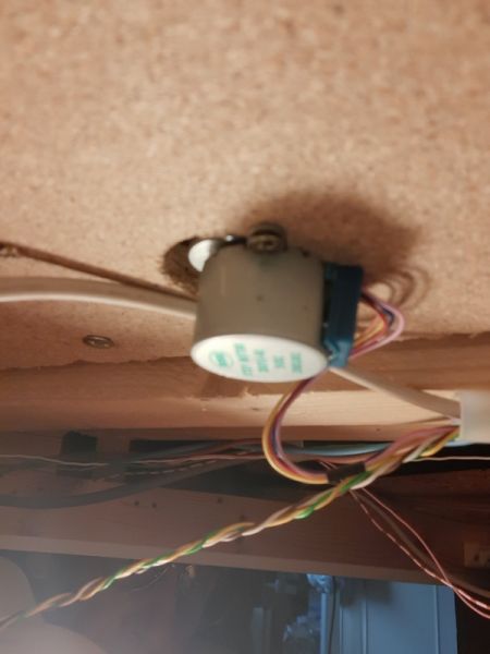
A bit out of focus but you get the impression of how the stepper motor was mounted on it's sub-board.
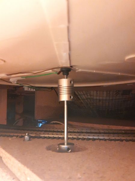
Showing the coupling rods between the stepper motor (under the boards) and the base of the turntable.
As mentioned before, the stepper motor is driven by the ULN2003a driver chip which, in turn, is driven by the PICAXE 18M2+ microprocessor and is set up and controlled by four buttons on the small control box close to the turntable. The buttons on the main mimic panel have yet to be installed - but the cable is in position (from the old motor controls). The small control box and the microprocessor board were shown a couple of posts back.
I would include a video of the turntable in action - but a turning turntable is a turning turntable and other than that, nothing else moves, only the twinkling of the four LEDs on the driver board that indicate the motor is being driven. I have, however, added a photo of the turntable complete with V2 60862 waiting to be turned ready for it's next assignment.

60862 sitting ready to be turned for its next assignment.
Overall, I'm quite pleased with how it works - a few minor tweaks, both to the program and to the mechanism, still need to be made then it's "a wrap" as they say and I can move on to the next project - maybe the signalling - maybe running a few trains.

Posted
Inactive Member
It sits nicely in the surrounds.
Cheers
Evan
Posted
Full Member
:cheers
Posted

Site staff
Great Job and glad you made it out from under there in one piece ! Albeit a bit twisted and bent

Cheers
Matt
Wasnie me, a big boy did it and ran away
"Why did you volunteer ? I didn't Sir, the other three stepped backwards"
"Why did you volunteer ? I didn't Sir, the other three stepped backwards"
Posted
Full Member
OK Matt, I get it - and thanks for your comment also. I guess there is a degree of interest in watching a turntable turn. To me, it's purely functional; it does what it says on the tin.
I'm almost there with getting it setup - the "prototype" as in my last description works well. However……
Although it lines up "very" well in the clockwise direction, there's an issue when going anti-clockwise - the first alignment is somewhat out of adjustment. I think there's an error in the program somewhere; not sure where at the moment. And another thing - it's a bit jittery. I think this will be nothing more than an alignment adjustment between the motor and the turntable deck.
So, bear with me for a few days or so till I get these niggles sorted. Then I'll see about a video of it.
Posted
Full Member
After trying to get some better alignment through adjustments to the motor mount - and failing- it was decided to scrap the idea and to modify the original DC motor mount - well, after all, it did seem to operate smoothly enough, so I guess the alignment was good enough. The motor mounting holes needed to be moved slightly to take up the difference between the two motor mounting holes.
I don't think the jitteriness of the deck is so much the fault of the stepper motor (the "motor", not necessarily the included gearbox). The motor might appear to be strong enough to turn the deck; but some more testing needs to be carried out, even to putting the old DC motor back in temporarily to see how it behaves (from memory, I seem to think it worked ok - even if it didn't align correctly [different methodology of aligning]). I think a lot of the problems with this small stepper motor stem from the amount of "backlash" there is on the gearing. Unfortunately, the amount of backlash appears to be non-consistent; if it was consistent, some additional code could handle it. If it is the case that the motor/gearbox is not up to what is required of it (i.e. counting a specific number of steps in either direction, repeatedly and accurately), then I will have to go up-market and buy a more powerful stepper motor with the planetary type of gearbox where there is (reportedly) very little backlash, and which could be consistent and be programmed around.
I guess it all comes down to 'what can you expect from a small motor and driver chip that costs less than a fiver!' Same old adage, you get what you pay for - but it's been an interesting initial step into the world of stepper motors.
Oh well, back to the drawing board. I WILL get it working.
Posted
Full Member
:newSo please don't think I am trying to teach you something you already know, apologies if I am, but have you considered something like a Nema 17 stepper motor? Example Nema 17
They are not too expensive, they come highly recommended by the Robot community and can be manged nicely with Arduino etc and the appropriate motor shields.
Might help with your research?
Alternative Stepper
Low cost StepperDriver
Cheers Andrew :cheers
 Last edit: by Andrewdonald
Posted
Full Member
Yes, I have looked at the NEMA17 stepper motor (also at the smaller/lighter NEMA8 & 11 versions) but have been uncertain regarding the final output step angle, given these motors have a nominal (without a gearbox) step of 1.8 degrees (200 steps per revolution). I've not found any information as to what the final (output) step size would be on a motor with a 5.18:1 gearbox using direct drive from a processor - the only reference to the output would be the fitted gearbox ratio and I have an issue relating the motor step size to the actual output step. I'm sure it's pretty straight forward, I just haven't twigged it. Does 0.34 degree per step (full stepping) sound right? If not, I still haven’t got the maths!
Looking at the practicalities of using a 1.8 degree stepper (no gearbox) over the span of (half) the turntable gives a difference between one step and the next to about 4mm (centre-to-exit). So a gearbox is, I think, essential to reduce that step span. Or…..
Having said that, looking at the EasyDriver board running on 1/8 step might appear to give a 0.2 degree output step. Hopefully I've got that right(?) and would negate the need for a gearbox! I also saw on another website for a NEMA17 motor that it would need to be connected to "a constant current or chopper drive controller before you test motor." Guess this might also mean using the EasyDriver board.
I've read all this stuff before, but I guess I've not taken it in and understood it. But having looked again and further, something is starting to sink in.
But, I had this small 28BYJ-48 motor in my kit already and thought I might be able to press it into service for this update project - after all, I've seen it used in other turntable articles across the Web - if other folk can do it……etc. - and the output step on it is reported to be under 0.1 degree (half stepping) - I'm not sure that level of accuracy can easily be beaten.
So yes, I still would like to use the BYJ stepper if possible, mostly due to its step size, physical size/weight and it was already in my kit box, but I fear the gearbox may be letting the project down with its backlash which I get the impression might be variable (and how this can be, I'm not sure - I'm more into electronics, not mechanics).
I'm still in the process of tweaking the program that runs it - it may or it may not have any bearing on its operation. But it's a lengthy process given a lack of spare time I'm able to give to it. Incidentally, the turntable deck seems to be relatively free-turning, so I don't think this is the problem.
I'm certainly open to suggestions and/or further advice on how this BYJ might be made to work better, or on the installation and/or running of the NEMA motor series. I know I'll need an H-bridge driver (i.e. the EasyDriver board using the Allegro chip) rather than the current ULN2003a and the BYJ motor can be converted to bipolar operation for greater torque (with an H-bridge driver). I'm trying also to keep the downward weight on the turntable to a minimum to (maybe) reduce wear on the plastic fittings of the turntable components. And space is also a major concern due to the proximity of tracks running adjacent to the motor positioning. A large motor was never planned for!
I found this website that appears to give a lot of good information on driving these stepper motors and with the EasyDriver board:
https://www.schmalzhaus.com/EasyDriver/index.html
There are other boards similar to the EasyDriver that use different Allegro chips and I need to work my way through and see if there's any relevant advantage of one over the other - Allegro chips such as the A3967 (EasyDriver - up to 1/8 step), the A3983 (Big EasyDriver - up to 1/16 step) and the A4988 (Pololu Black or Green - up to 1/16 step).
I've seen one stepper motor that might suit what I'm looking for:
NEMA17 Bipolar 1.8degreee 0.4A 12V - reasonable price, together with the
BigEasy Stepper Driver - although I'm not sure of the benefit of this over the (cheaper) EasyDriver other than increased current handling and 1/16th stepping.
I note that the code snippets I've found to date are all making use of the Arduino as the driver source; but not having much of a clue about C+, but plenty of experience with PICAXE BASIC, that is the way I'd be looking to go with this. I see no reason why it can't be done. Surely, all I need to do is output a series of pulses at a given timing for a given speed. Or maybe I'm being TOO simplistic here. Surely the Allegro chip does the donkey work.
There's so much I don't know about stepper motors and how to run them. I need to learn from those who have the experience of them. I wonder if there's a "Dummy's Book of " for them! I could do with one.
Posted
Site staff
Motion Control Drive Tips
HTH
Cheers. (A VERY confused)
Matt
Wasnie me, a big boy did it and ran away
"Why did you volunteer ? I didn't Sir, the other three stepped backwards"
"Why did you volunteer ? I didn't Sir, the other three stepped backwards"
Posted
Full Member
Your thread is becoming a bit addictive and has peaked my interest in building a DIY turntable mechanism. I have a kit built CNC machine and a kit built 3D printer, so I have a bunch of spares lying around, including motors, drivers, Arduino board etc. So I am very tempted to have a crack, trouble is the TT could turn into a hobby in its own right, but I need to get on with the layout and not get distracted………… I have a bad habit of not finishing things and I have the layout to build, computer control to get figured out and now a TT to build :roll: :roll:
However, I will continue to research the TT as computer control, due to some early wrong decisions, is problematic for me right now. I will continue to watch your progress and, when I get a chance, replicate some of the ideas that are floating around the net - there are a lot of them, and give you some feedback if its relevant. OR, I will simply copy your solution when you get it worked out :doublethumb
Cheers Andrew :cheers
Posted
Full Member
I've occasionally been having intermittent shorting out problems of the track DCC power while locos have been going over the Peco Insulfrog cross-over (SL-93) part of the layout. Resulting in the whole DCC system shutting down and everything coming to a sudden halt. It's been bugging me for a long while, but I've never really thought about getting my head around it and getting it fixed for once and for all. Until now, that is.
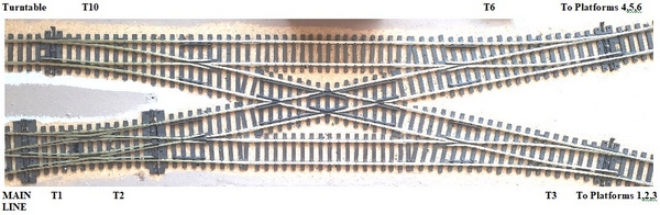
This is an overview of the approach throat to the Terminus.
Insulating joiners were used where appropriate at each of the points thinking the nature of the Insulfrog cross-over would take care of any shorting out issues while leaving the cross-over fully "live". But I have a few "older" locos where the width of the wheels (and possibly the side-to-side shifting) are just too great and they occasionally bridge the gap - and (not literally) "bang", no power. The shorting-out points being at the circles on the photo below where the gap between opposing rails is relatively narrow.
After much searching of the forums, etc. and having come up with no real solution to it - other than the option of using nail vanish to insulate a small part of the rails where they are relatively close to one another (that wasn't overly successful) or maybe an expensive Hex Frog Juicer (polarity reverser, so I understand) or an in-line car bulb - there must be a better, simpler, more certain way of doing it.
I tried looking at using the electrofrog switching of the adjacent points to make it work; but I could see I was still likely to get the possibility of shorting out. So, in order to achieve the isolating of the non-required-to-be powered cross-over rails a bit of logic (chip-wise) was employed, together with a couple of relays and a few other bits.
The idea being that the cross-over was to be totally electrically isolated from any adjoining rails and from the main DCC bus that connected to it. DCC power feed wires are passed to each of the coloured rails via the relays. This involved an in-situ retro cutting of (electrical) joiners on some of the rails (some were already insulated). That was fun - not!

Peco cross-over showing the "danger/shorting-out" locations
The relays used are small 12v 2Amp DPDT, small signal MOSFET transistors to drive the relays (2N7000 or similar) together with the logic chips - a 7404 inverter and a 7408 AND gate - a pair of optional LEDs to confirm there IS power on the cross-over as well as an ERROR indicator LED to show that both cross-over tracks are live. And a piece of stripboard to mount it all.
These particular inputs to the logic chips are just how the points and mimic panel indicators were set up on day one of this layout some years ago. If any of the "indicator" voltages are incorrect to the logic (i.e. points not correctly set), the cross-over DCC relays will not switch and the cross-over will be un-powered. Only when a valid "path" is set across the cross-over will power be applied to those rails and not to the opposing/adjacent rails, i.e. if the "path" is across from bottom left to top right (in the photo above) only those rails coloured orange and blue will have power applied. Should both sets of rails be powered, the "error" LED will light.
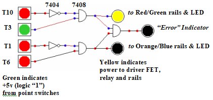
Basic logic diagram showing inputs from the attached points as +5v (green) and 0v (red) and the yellow indicating power is switched to the red/green rails and not to the red/blue rails or to the "error" LED
This arrangement is specific to the John Street station approach. But the idea should be easily transferable. The method I use of mimic LEDs for point settings is +5v and 0v is put to either side of the points switch and the switched output is taken from whichever way the points (and switch) is set; +5v or 0v is put to the mimic board LEDs
Given the logic (and input voltages) as shown, the red/green rails LED will be "ON", indicating that that cross-over track is "live" and the error LED will be "OFF" indicating only one of the cross-over tracks is "live", therefore, there will be no chance of wheels shorting the DCC power. As it stands both sets of cross-over tracks can be live at the same time; a bit more logic could have prevented it but why over complicate it all; but the error light is there to show both sets of rails are live, if that is how the points are set.
One point to bear in mind is that each standard logic gate (from the now obsolete 74xx series) can supply 16mA whereas the low power (74LSxx) can only supply 3.6mA. This would indicate the LED current levels need to be limited to around 10mA; standard 74xx inputs require 1.6mA and the MOSFETs used very little (they are voltage driven). All a bit complex, but I managed to use a 74LS04 and a 7408. The two families do work together but there are times the input/output figures need to be bourne in mind.
I've never had a lot of experience with 74xx logic chips and the output voltage from the AND gate surprised me. One small thing I didn't realise until I started building this up on the breadboard, was that the output from a logic chip may not be the expected +5v but could be anywhere between +2.7v and +5v (this is the valid logic "1" level range and is acceptable between 74xx logic chips) - We live and learn! - in my case, the output from the 7408 AND gate came out at +3.9v and initially I wasn't sure that was enough drive voltage to fully turn on the 2N7000 MOSFET and switch the relay. I attached an LED to the gate via a 330R and found the LED current was just over 4mA with the gate voltage dropping to +2.9v - still enough to switch the relay. I'm not sure just how much of this was related to using the breadboard rather than final pcb mounting as figures were a little better when on the pcb itself. I'm not a fan of breadboarding, but it can prove a circuit before committing it, so it does have its uses.
I did read that one way of getting around this low output voltage, if being used to drive other devices such as the MOSFET, is to use a "pull-up" resistor of around 2k2ohms on the output of the logic chip, in this case, the 7408. The MOSFET requires a minimum voltage to begin to turn it on and the +3.9v I suspected might not be enough to turn on the MOSFET sufficient to switch the relay. I tried this (but with a 2k7) and found that the voltage actually dropped - how this could be, I have no idea. Anyway, it seems that the +3.9v (without the resistor) put to the gate is enough to turn the 2N7000 on and the relay to switch over.
This is turning out to be more of an exercise in electronics rather than solving a basic track/DCC shorting out problem. The now ageing TTL Cookbook (Don Lancaster) is an invaluable source of information regarding the pinouts and use of these logic chips; available to buy from the likes of Amazon or is freely downloadable.

Final circuit board showing the logic chips, the MOSFETs and power relays
So now I have the confidence to run trains over the cross-over without the threat of losing DCC power due to it being shorted out.
As an aside to this switching of DCC on the cross-over. At the moment I use four separate changeover switches to change each of the points attached to the cross-over. Another way of selecting the route would be to use a diode matrix that will select the appropriate track(s) as I've used elsewhere on the layout. See https://www.brian-lambert.co.uk/Electrical-Page-3.html (about half way down the page - The Basic Matrix) for instructions on the "how-to" create and use a diode matrix. The problem here could be that the CDU might not be powerful enough to switch 4 Peco point solenoids simultaneously. So that might also need to be looked at some time in the future. Or just run with what currently works.
Hopefully, now this part of the layout will be able to operate without the fear of it all being suddenly shut down.
Will I next get back to the signalling…….watch this space!
Posted

Site staff
The problem here could be that the CDU might not be powerful enough to switch 4 Peco point solenoids simultaneously. So that might also need to be looked at some time in the future.
Try this one as one of my mates here in South Aust uses it for what you want
Intergrated CDU Unit Dual High Power CDUs. Super High Power.
Ron
NCE DCC ; 00 scale UK outline.
NCE DCC ; 00 scale UK outline.
Posted
Full Member
Thanks Sol, appreciate the pointer. I prefer to go down the DIY methodology personally - if at all possible. But I agree there is always a place for a shop-bought item.Try this one as one of my mates here in South Aust uses it for what you want
https://www.dccconcepts.com/product/power-supply-integrated-cdu-unit-super-high-power/
The current CDU is home-brew powered from an old printer power pack and a few odd components literally hung together (nothing neat!). It might even work "as is" for switching the four points. Derived from that published on Brian Lambert's excellent pages - the Advanced CDU on Electrical, page 3, using a 4700uF capacitor. It should be large enough for the job. Maybe one day.
But thanks again for the pointer if all else fails.
Posted
Full Member
Regards
Roger
Last edit: by fourtytwo
Roger OO DC Steam
Posted
Full Member
The CDU I use, as mentioned above, is taken from Brian Lambert's pages but the point motors are driven from the circuit by Ken Stapleton's 751D MOSFET circuit (using the IRLU014 MOSFET) by giving a short pulse to the MOSFET gate via the in-line 22uF capacitor rather than having the total capacitor charge released under, what might be regarded as, more normal operation. It works very well if, and only if, the input/drive voltage applied to the gates/22uF is NOT the +12v of the circuit. I was seeing +11.7v put to the gate on the switch change. The spec sheet shows a maximum of +10v to the gate. I blew a few of these MOSFETs before I took a look at the pdf and found out why. Not blown one since I now only apply +9v to the gate. Lesson here is, never take a published circuit at 100% proven. But then again, I've not used the diode in the main feed - but that would only reduce the supply to around +11.3v, still too high for the MOSFET. (whether it also provides flyback issues is another matter - ??).
Maybe I'm over-driving the power level to single solenoids, but so far, touch wood, nothing has failed in this area. Tomorrow may be a different story! But I think, maybe in total innocence, that the MOSFET circuit is preventing any over-powering problems.
Dave
Posted
Full Member
It seems my attempts to get it to work are simply fraught with issues - non-alignments (sometimes by a 'mile') and then only able to go clockwise (due to backlash). I've re-visited the code and all seems to be ok on simulation.
So it seems I shall have to think it out again - at least the motor.
Looking back at Andrewdonald's suggestion of 5 April, I've again been looking at the NEMA 17 stepper motor together with Sparkfun's Easy Driver board, together with my PICAXE to count the steps and (hopefully) get the alignments correct.
The stepper would appear to be slightly stronger that Andrew's suggestion, giving 36.8oz (26Ncm) torque at 400mA, 12v. But we're in different countries, etc. etc. and this is available locally and at reasonable cost.
My only issue will be with mounting it with minimal vertical misalignment issues. So that's something I'll be working on over the next week or so, time permitting. And there I was hoping to get on with the signalling again - some chance!
I'll keep it updated here.
Posted
Full Member
Glad to see you are working the TT problems through. I think the 17 steppers will be absolutely fine for the task in hand. The holding torque demands of the turntable will be very small and well within the limits of the motor.
As I said earlier, your thread has really got my creative energies flowing. While my layout work was on a short pause last week due to ANZAC day preps and commitments, I spent a fair bit of time thinking about my prospective turntable project. I will post some initial thoughts in my Dentith Bridges Underlying Technology blog today.
Cheers,
Andrew :cheers
Posted
Full Member
I've at last bitten the bullet, so-to-speak, and gone and ordered a NEMA 17 stepper motor and a bracket to mount the thing. I also "tried" to order an Easy Driver board to give the microstepping requirements that should allow accuracy of alignment to the tracks. Both of these purchases were fraught with problems. Why is nothing straight forward these days?
The order for the stepper motor initially didn't go through - the seller's website failed to acknowledge the payment initially - so a second attempt had to be made. Successfully this time. So, hopefully, there's only one motor ordered. Royal Mail says there are two packages for me (due tomorrow, Tuesday). Whether this is a duplicated order or the two items were sent separately, I have no idea at this stage. Time will tell.
And ordering the Easy Driver also ended more so in failure (I think) than that for the motor. I tried with both Firefox and with Chrome (sometimes websites don't like FF for some reason - yet I prefer to use it). Again, there was a total failure of the seller responding to the order - it just kept returning me to the order page and the 'go to checkout' screen despite having gone to the checkout and entered the required details (twice) and with no error or missed detail being reported. I've phoned them - no answer, so left a message (premium rate number, aghhhhhhhh!) and sent messages and an email and I get no response - that was last Thursday mid-afternoon. They were quick enough to respond when I questioned them on the board's version number they were selling (web picture showed an earlier version than the latest incarnation). I now sit and wait a day or two to see what, if any, response I get back after the bank holiday - then I can safely order from another supplier (only costs an additional couple of pennies, so no real issue there) and knowing I'll not be duplicating the order.
In the meantime, I have been closely measuring up the size of the motor and its mounting (from the site's pdf data) to see if it will fit in the limited space available from where the original DC motor, and latterly, the BYJ motor came from. It should fit comfortably enough, missing the longest rolling stock by about 10 millimeters; although I do need to remove a bit of the baseboard overhang to assist in the mounting process.
And the program to run it has also been re-looked at and is close to working as required.
All systems are 'go' for the updated (again) turntable. More as and when I get it fitted and - with any hope - working. If this fails, it'll be a "crank it by hand" job!
Cheers for now….
Dave
Posted
Full Member
Sorry to hear about your issues with the online vendors, I hope it all works out well for you. I have been lucky, touch wood, so far, but down here we do have issues with international post…..
Glad to hear you are still cracking on with the TT though :thumbs. Later this week I will have scrounged all the bits I need for a prototype set up so please, let me know if there is anything I can do to help on the software and stepper management side - testing code, running different versions etc.
Cheers, Andrew :cheers
Posted

Full Member
I'm following (bits) of your journey but there are lots of "dark side" inferences which, to me, are best left for those with bigger brains than I.
I do applaud your meticulous approach to the electronics but then I suppose one has to be meticulous with such things. I have every confidence you'll get there in the end - postal services willing but I'll leave the electronics to others when I bring my turntable into use…………. :cheers
'Petermac
1 guest and 0 members have just viewed this.