John Street - BR(E) - 1960
Posted

Full Member
My second bash at model railway-ing
Following on from my previous….and that of Nov last year #110…..Various reports have been read about jittering/stuttering servo motors and that they do seem to be prone to this sort of issue when being run at a slow speed. The operation of the gates works fine, no problems - but they stutter and flap about a fair bit as they open/close. Not ideal to watch. Yet I've seen videos of gates using these SG90 servos that appear to run smoothly. How, what they do that's different, I have no idea.
Modifications such as adding a resistor in-line with the data input to the servo - something in the order of either 330 ohms, or anything up to 10k ohms. The 330 ohms didn't do it for me - maybe I'll try the 10k and see how that performs - but I'm not holding out much hope here.
Another fix is to add copious amounts of capacitance to the actual supply from the +5v regulator (7805) to the motor to make up for any possible voltage brown-outs due to the current being taken by the motors - only one motor runs at any one time. I added something like 4600uF. Made little or no improvement.
Not overly happy with it.
The program that runs the level crossing (from a PICAXE 18M2+) does have an 'interrupt' routine included to watch for the approach of a second train over a sensor such that the gates are kept open once the first train has passed through. I doubt that this would have any effect what-so-ever other than to slightly slow the motor; but that slowing is taken up by reducing a pause command. So that one balances out the other. Maybe I'll drag out the oscilloscope and see it that shows anything - but even with that, I'm not so sure it will show anything. I think it's just the nature of the beast.
The program uses what is known as a "bit-banging" routine that uses the PULSOUT command rather than the more normal SERVO and SERVOPOS commands. These latter two are well known for producing jitter (stuttering).
So, unless anyone reading this has any bright ideas of how this issue can be improved upon, I think I shall have to go down the route of ditching the servos and running small DC motors with, maybe, a pulse width modulated power signal to give it the variable speed to suit the simulation of correctly operating gate speeds. I've seen reports of something that might suit - from rapidonline.com (no connection) for the MFA-917d motor/gearbox driven by such a power signal - at http://richardstransportpages.co.uk/levelcrossinggates.htm
So that's something fresh to work on. One day I'll run a train or two.
Maybe!

Posted
Full Member
Sorry to get you thinking about semaphores again. No doubt about it, they are more ‘attractive’ than colour lights, but equally they are in a different league when it comes to adjusting them to get the action just right. With my Heath-Robinson method of motorising I need a fair amount of space under the layout, likewise the Dapol offerings, and where that’s not available the colour light is the only option. That gantry you have constructed is most impressive. For me a layout has to have signalling, it is an integral part of the railway, and if the signals are operational so much the better.
I assume you have a list to which you can add the Ratio signal, one of my lists includes an operational Ratio ground signal – I suspect there’s more chance of you producing something before yours truly.
Your most recent post convinced me, not that I needed much convincing, that I made the right decision in sticking with my 1960s electrics, my overworked grey cell just couldn’t cope with all that technology!
Keith
Do I have a plan? Na, if I did I'd spend most of my time trying to remember where I put it.
Posted
Full Member
I'm starting to get the impression my grey cell has taken a sabbatical or keeled over with this virus thing as I can't seem to focus on anything much these days - and the lack of the mojo isn't helping either. Like you, signalling - along with anything else you could find on the real railways, more so if it "moves" or "does something" is just as important as the trains that move.
I've always been into electronics since a young lad (more years ago than I care to recall!) and I'm no more happy than when I'm messing with a length of wire and a soldering iron. Yes, and the brick wall comes into it quite often

And, the old semaphores do have a certain magic about them - but colour lights are easier to make up and to install - and that I can fully embrace these days. But after seeing your semaphore, I felt I just had to have at least one of them. Nostalgia is a wonderful thing.
Don't worry about Heath-Robinson - he's my Hero. Some of the things I've cobbled together would make even him blush. Word of warning, don't look under the baseboard - ever! It'll scare you half to death.
You mention the Ratio ground signal - would that be the colour light version or the older mechanical one? I wanted to try for the mechanical version (fitted in with the 'period' better), but they look way too fiddly for me. I have a Ratio version on one side (had it years) - hopefully it's still on a list shortly after getting the signals programming up and running and until the grey cell comes back from it's vacation even that's a long way in the distance. Oh, and thanks for the comment on the gantry - good to have your approval, appreciated.
Ah well, back to the drawing board. What's next for the build? Still puzzling on the level crossing gates - I'll not be beaten (he says!).
Cheers
Dave
Posted
Full Member
That is a perfect description of the state of my grey cell too, definitely something to do with this enforced change to our ‘routines’. As for the ground signal, it is the older mechanical version. Yes fiddly doesn’t really convey the likely impossibility of the task. That said when I get a good day with the fingers, and my patience levels are at an all-time high, I have an idea of how I could attempt it. I have to admit that I have already bought some of the DCCconcepts colour light variety as cover for when the poor old grey cell finally decides ‘enough’.
Keith
Do I have a plan? Na, if I did I'd spend most of my time trying to remember where I put it.
Posted
Full Member
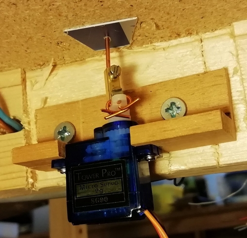
At last I've been able to get them working with very little in the way of jitteryness and flapping about. I guess that's the best I can hope for - certainly much better than before. It's really been bugging me! Other videos I've seen also appear to have some slight jitteryness about them, so I'm ok with where I'm at with this. I've taken out the direct, vertical linkage from the servo to the gate, as on the photo below - not 100% accuracy on alignment of the wires and the (necessary) small diameter of the hole either side of the baseboard that keeps the gate pivots in the correct position and thus causing a degree of binding:
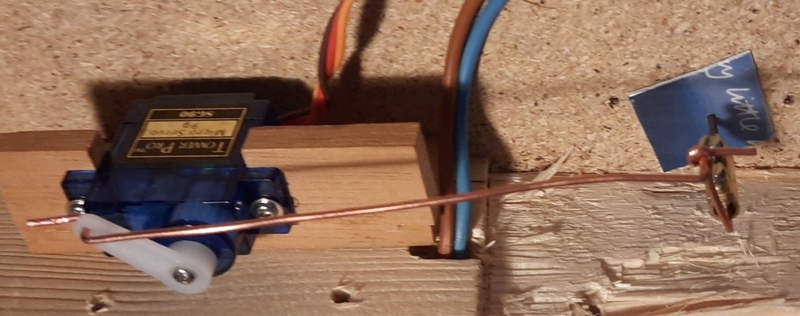
and replaced it with some linkage wires with the servo slightly remote from the gate pivot:
There's a more detailed write-up on this and on other aspects of automating various items on the layout in another series of posts I've added to the YMR site, at http://yourmodelrailway.net/view_topic.php?id=16438&forum_id=7&jump_to=295745#p295745.
Hopefully, I can then keep this post to matters more akin to the layout overall.
Talking of which…… I still seem to be struggling with keeping the grey cell focussed on the task at hand. And life in general hasn't been too kind recently either in not allowing me much time to devote to the modelling of John Street.
I'm still working on the signalling for the layout - programming time is in short supply these days - but it is getting there, slowly but surely. At this time it will be all colour light signals but with the proviso that at least one semaphore will replace one of the colour signals. Mainly because from the operator position, I cannot see the colour aspects from this one signal and the inclusion of a semaphore will allow me to see (a) what the signal is displaying and (b) some animation. It would all fit in nicely with this one area of the layout being (a) at a location with a small halt station (to the rear of this photo) with access to a siding (coming in from the rear, left), (b) in close proximity to the signal box, and © which also controls the adjacent level crossing, below.
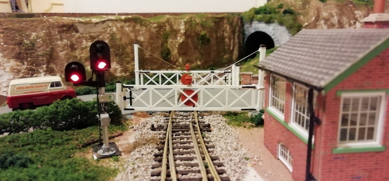
A bit of an old photo as both signals are currently three aspect (and the van has moved on as well). This will be the signal to be replaced with the semaphore - if I can get this job further up the to do list - and if I can find sufficient space under the baseboard to fit servos or Tortoise motors.
I'm not 100% sure that this would be the type of signal to be in position at this location - controlling the mainline and the exit from the siding (coming in from the left). From information found, this arrangement would be more likely for a "diverging junction" rather than "merging" tracks. Maybe I could put this down to "modellers licence". I don't really have enough room to have the two signals on separate posts - given the visibility that would be afforded to the loco driver. Any advice out there would be appreciated. Thanks.
Posted

Full Member
Apparently Dave Fenton, the owner and designer of Megapoints did some research and solved the problem "perfectly" (according to the happy author of the article).
No idea what he came up with but it might be worth contacting him for discussions………….. :roll:
'Petermac
Posted
Full Member
It seems these small airplane type servos (such as the SG90) can be prone to such jitter effects. Anyway, I've emailed Dave and hoping he might be willing to impart what his "fix" might be. If it's within the software he uses, then I've little or no chance of being able to replicate it as I would expect he might use the PIC chips whereas I use the PICAXE chips - same basic processor, but the programming language and methodology differs.
Maybe, I'll strike lucky and he offers his fix and is down to circuitry (components) rather than programming.
Posted
Full Member
'Petermac
Posted
Full Member
Had a very nice reply from Dave this evening but unfortunately he uses a different processor, thus different code, and which he says "For our system we kept tightening the code until we had it eliminated. Tight and accurate loops or interrupt routines work great until you pile in application logic."
So regrettably he was unable to give any pointers with regard to the system I have made use of. But it was worth a try and I thank you for the pointer in his direction.
In the meantime, I shall continue with where I am and see if I can improve on what little there is of the jitter, minor though it may be, with my setup. Mostly I feel it is down to the flimsy nature of the gates themselves and possibly very slight binding in the pivot combined with the inevitable step-stepping nature of the servo itself. The steps, although small, are still steps which means there's movement followed by non-movement followed by movement, etc. and this cannot be improved upon without decreasing the step size and that just is not possible with the SG90 servo. You simply cannot achieve a half-step. It's the nature of the beast. Maybe slightly altering the speed of movement might get away from any oscillation effects that are being produced so long as the speed is not altered by too much making them swing either too fast or too slowly.
Maybe some strengthening of the gate structure might help with the addition of some thin piano wire discretely fitted to the gate and maybe a sight dab of grease on the pivot holes might also assist. A few things to have a go at.
So thanks again and when I get the time I'll revisit the issue and see what I can do to improve matters.
Dave
Posted
Full Member
I hope you can sort something out.
'Petermac
Posted
Full Member
Basically, not much has been done to the layout itself. Simple as. The mojo has certainly taken a hike just recently; I simply can't seem to get focussed on anything much. I blame this Covid issue and the amount of publicity it seems to be (quite rightly) getting. If only everyone followed the rules then we could all relax a little; but sadly not so.
Quite a lot has, however, been (occasionally) going on in the background though, such as progressing the signalling side of things. The programming is more-or-less complete - so that's one thing, just the inevitable tweaks that will no doubt crop up once it gets on the layout and working. The circuit board is well on its way to being completed - the chip sockets are in place ready for the processors, logic chips and current drivers along with the current limiting resistors for the signals. It's starting to look promising! I now need to get the remaining sensors fitted - some are already in place - and then I can get it all connected up and hopefully I might get some working signals on the layout - and a great big thorn out of my side as well! It had better be worth all the effort!
The signal LEDs will be wired up effectively back-to-front due to the current drivers being in-circuit. All the anodes are connected to the positive voltage rail while each cathode is connected to the current drivers (via current limiting resistors) which pull the cathodes down to 'ground' and thus allowing an electrical path and lighting the LEDs. The current drivers are either ULN2003a or ULN2803a (7- or 8-port devices) and they get their individual turn-on signals from the processor outputs.
One item added today to the layout has been some AWS ramps. Nothing spectacular, but they just add a bit of detail to the trackwork. I needed to do "something" to the layout - and this was it. Relatively quick and easy to do - the longest part of it was waiting for the paints to dry! I like watching paint dry; most therapeutic!
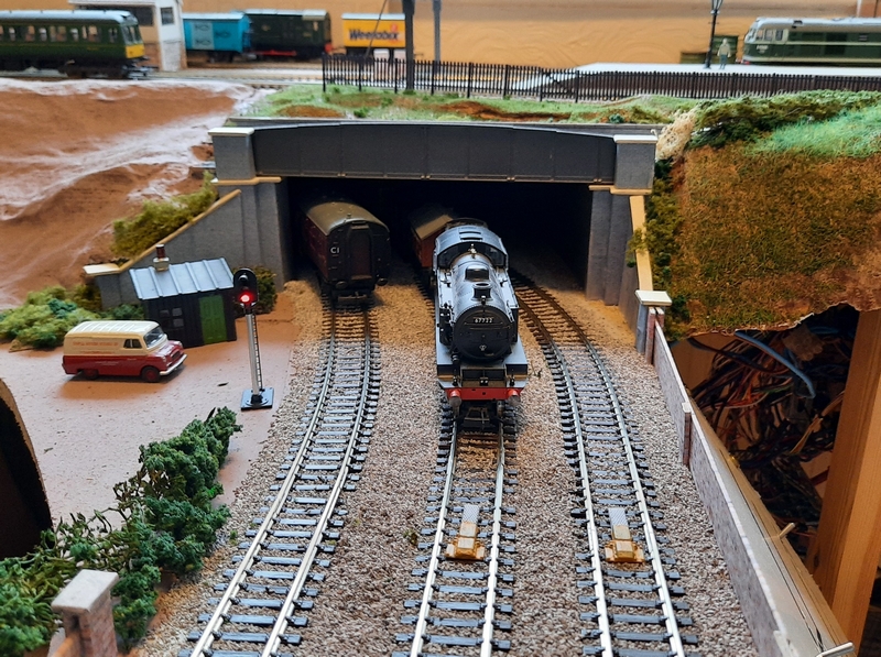
A shot of a pair of AWS ramps on the lead to the signal gantry further up the line, together with Thomson Class L1 67722 on approach. In the background can be spotted Class 31 D5509, a Class 117 DMU approaching the terminus and Class 08 D3032 on shunting duties in the background. A good bit more work yet to be carried out on the scenery side of things to the left of the tracks and the adding of some capping to the brickwork pillars on the right.
And anther item being looked at has been making bushes from hemp rope strands. My first attempt looks pretty good (even if I say so myself!) - more work is needed to hopefully make them look a bit more realistic.

The camera on close-up can be so harsh and critical! Hopefully, it'll look better and blend in more once on the layout. But I've made a start.
Posted

Full Member
You're getting something I've never sorted out, flock, leaf etc. that refuses to stick to the ends of the finest stems however much spray adhesive you apply. I had the same trying to complete my hedgerows, often I just oversize the substrate and give it a haircut to size but it remains one of life's minor puzzles.
Posted
Full Member
Basically I just soaked the entire bush (naked hemp strands) in PVA, waited a minute or so for it to become a bit tacky, then sprinkled it with (or dunked in) loads of scatter. Wait till it's dry, gently shake off the unstuck material, then if any bits need topping up add a dab more PVA and repeat the process. Seems to have worked relatively well. Even so, there are still a few strands that need trimming. Work in progress….. perhaps with some smaller/different scatter material.
Posted
Full Member
I've used the very fine Woodlands Scenic Fine Turf products (T44, T45, T49; progressively darker green shades) as a bottom layer before overlaying larger leaf type products such as Noch Leaf (07142, 07144) which represent very large leaves or flock for smaller leaves.Work in progress….. perhaps with some smaller/different scatter material.
I'd been using a spray adhesive but will try PVA. Presumably you use it diluted as 100% would be impossibly thick. What ratio dilution do you use?
For larger shrubs and trees I also try to keep lower and inner branches relatively leaf free since they mostly grow on the edge of the canopy. This is where spray adhesive tends to be a bit better with more lodging on the outer edges.
Of course you could argue that I found the "perfect" leaf solution as my Weston-Heathfield is now modeled for a winter setting!! But then with my lack of progress this COVID Winter in Oz, Spring will be back at W-H before you know it.
Colin
 Last edit: by Colin W
Posted
Full Member
Hi ColinPresumably you use it diluted as 100% would be impossibly thick. What ratio dilution do you use?
Ratio of PVA to water? I can't really say for certain - far from 100% PVA. Probably something like 4 parts water to 1 part PVA and possibly a bit of washing up liquid thrown in for good measure! It's been quite a while since it was mixed for fixing the ballast to the layout. And with a memory like mine….. There's just no telling for certain.
I've been messing with making my own greenery with the aid of a nut grinder and some old foam and a bit of acrylic paint. Still early days with this but will see how that looks on some new 'trees' and 'shrubs' when I get round to needing a break from other things.
Good pointer though on leaving the inner 'branches' un-leafed. So thanks for that - will give that a try and see how we get on. As I said, it was a first attempt, so from here there's only one way to go - and that's improvement.
Dave
Last edit: by spurno
Posted
Full Member
This footbridge is from LCUT Creative (B OO-35 LNER style). I've had the kit for quite some long while and never found the time to make a start on it. Not quite sure where it will eventually live as yet - I had plans to put it at the back of the layout but it might yet live at the small halt, a bit closer to the operating position. It looks too good to be effectively hidden away across the other side of the layout - the jury is still out on this.
The kit is made of thin fibreboard that just needs the parts cutting out, cleaning up and gluing in place, and then painting. It's quite fragile and fiddly in places to construct, particularly getting the step rungs glued in place. The instructions were a little vague as to the order of construction and the best options of when to paint which part. Maybe it was just me - at least it is now completed and painted up.
The easiest method I found was to glue and insert the rungs on one side of the staircase, then dry fit to the other side before applying glue to secure them.
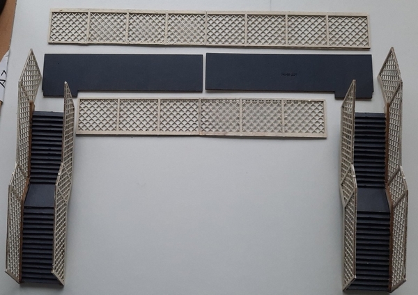
Parts were painted as the construction went along - the two parts of each of the balustrades were glued together then painted. Then the staircases were constructed onto the stair balustrades before the steps were painted along with the walkway over the tracks. Then there was a general painting of the BR(E) Blue on the main pieces of "steelwork" before the final parts were fitted together.
In retrospect, I think the order of construction and painting could have been improved. But in my defence, the instructions are, as mentioned previously, somewhat vague in this respect. It's a simple enough kit to put together - and the instructions generally serve their purpose - but I thought it would be easier to paint as I went along rather than after construction had been completed. Horses for courses I guess. And superglue was a better option in certain places rather than straight PVA.
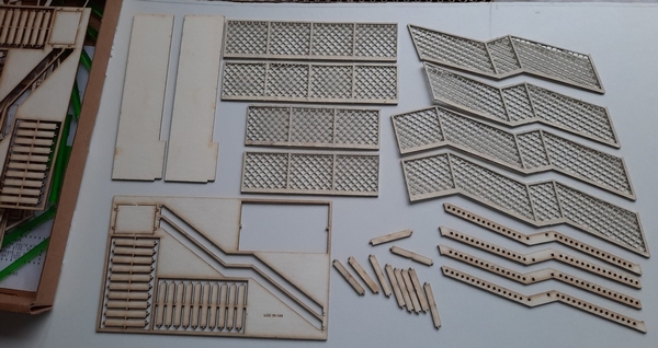
A few bits cut out and prepared

A start made with one set of steps glued in place
But, with a fair wind, a deft hand and a little patience (of which I tend to have very little at times!) a start was made and given an overall coat of cream….
A touch of paint to the steps and walkway…. and a dark grey for the steps.
Inspiration for the colouring was taken from that at Greenfield station and other locations (photos found from our ever-present search friend).

…. and the finished footbridge. Apart from the smoke deflectors which need to be added once a decision has been made for its final location.
At last, the finished "article" - sorry, footbridge. For now, it'll sit at the back of the layout leading to the houses and the factory unit there (planned but not yet built!) and pending a decision once the small halt area has been, or got nearer to, completion - starting it would be a good thing! That must be a job to go high on the priority list. Some basic marking out has at least been started for it. And then there are some houses to build up…… and…… and….
Back now to the signalling…..
Posted
Full Member
At last, I seem to be getting somewhere with my upgrading the turntable project to overcome track alignment/indexing issues.
I'm now at the stage where a dummy test jig has been built, along with a small control box (mostly to be used for taking to the turntable to do the initial setting up) and with the software written, testing has begun with good results. The actual "run-time" controls will be build/added to the main mimic control panel later.
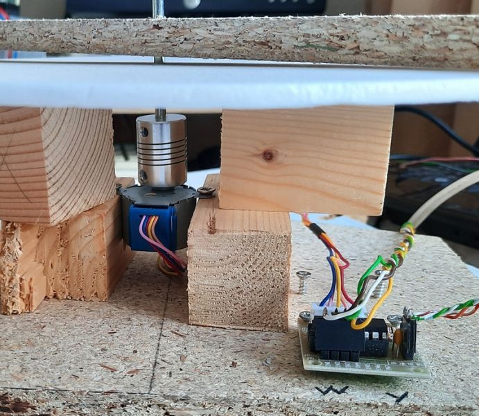
Overall view of the test jig - for checking that the 'kit' and software will actually work.
The motor is the small 28BYJ-48 +5v stepper motor - hopefully it will have enough torque to turn the actual turntable deck once in place - although I've yet to figure out how it will be mounted. The control logic is a PICAXE 18M2+ microprocessor mounted on a piece of stripboard along with a preset speed control that will adjust the speed of the turntable. I'm not too sure how long it should take for a 180degree turn - I would guess at about one minute. I'm open to suggestions on this….
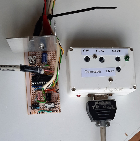
Control pcb (PICAXE 18M2+) and its (setting up) control box.
The motor is driven via the small ULN2003a driver chip that came with the motor. I'm not sure I want the flashing LEDs but they were useful initially while testing to know the motor is actually being driven (just in case the motor might appear not to be doing its thing).
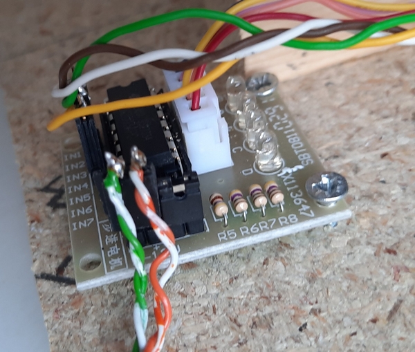
Motor Driver pcb (ULN2003a).
That's the first part done. Now all I need do is crawl under the layout in a very tight and restricted space to see about mounting the motor.
Posted

Full Member
Posted
Full Member
I agree, there won't be much to see when the PICAXE is in situ under the layout and the TT does it thing, like most turntables do. But, oh! the satisfaction of writing the program and getting it to work - shame that can't be put onto video; I'm sure it would be (almost) priceless!
Once it's all in and working, I'll post a couple of pictures of it in situ. It may take some time to get to that stage as the floor area on approach to that corner of the layout has become my workbench, dumpit ground and flea-pit - that is going to take some time to get cleared. And then I'll need to go on a diet so that I can squeeze myself in and under the layout into the very small space available for under-turntable access being careful of the (hidden) trackwork that runs very close to where the motor will reside. And the joints aren't as flexible as they once were…..
To date I've used PICAXE chips in motorising uncoupling ramps and the level crossing gates, both using small aero-type servos, a Home signal and theatre display, and am nearing completion for a couple of 40X2's running the signalling around the layout. Without running too much of a promotion for them, I think they're so versatile - providing some brain power can be utilised into their programming. Incidentally, I've no connection to the makers of these chips other than as a user.
So Dave, get 'em out and get programming!
Thanks again,
Dave
Posted

Full Member
Might go down this turntable path just for the fun of it…. I currently have a full head of hair to pull out.
1 guest and 0 members have just viewed this.