John Street - BR(E) - 1960
Posted

Full Member
My second bash at model railway-ing
Glad to hear you got the issue sorted!

Posted

Full Member
Until recently I've been effectively banned for 3 weeks from getting into the 'train room' or to do any work on the layout itself due to a leg injury (now well on the mend). Outside of this period quite a lot more work has gradually been carried out on and around the Terminus - it's still not quite complete (the photos on post #88/89 were 'of a time' and quite a long way off being finished) but I thought a further update was a worthwhile exercise. This further update is now overdue. So here we go….
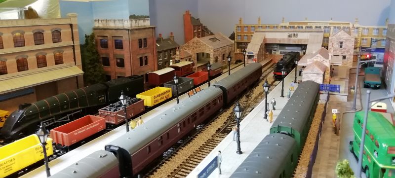
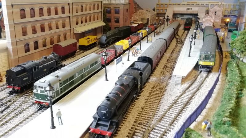
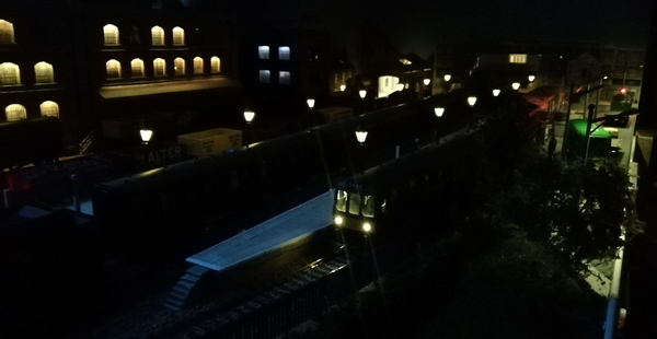
It's still not quite finished but ballasting has now progressed right across the terminus itself (not my favourite job!); station nameboards and platform lamps are now fitted (and working). Buffers at the end of each platform still need to be finished and fitted; one has been installed with others in the pipeline. I had wanted to use fibre optics for the end-of-line 'stop' lamps on the buffer bars - it would have been my first foray into fibre optics - it worked well at the end of Platform 1 (as per the photo) but fitting fibres to the end of the other platforms is nigh-on impossible - due to the tracks finishing up against a (real) brick wall and the fact that fibre optics do not like being bent at sharp angles! So fibre has been shelved - but I half expected this before I ordered the fibre, but I thought it might be worth a try. So I'm reverting back to using miniature 1.8mm LEDs. There's not much 'detail' in the buffer bars or the lamps themselves, but from a distance (the further the better, some might say!) they will probably look ok.
There's still a bit of "grime" to be added to the ballast in the terminus and (maybe) some rust on the rails themselves; oh, and also the terminus signalling.
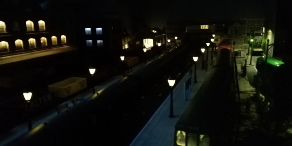
The street lighting had a slight modification by replacing the fitted (standard) 3mm LEDs with surface mount LEDs - now the light shines downwards rather than every angle you could think of, including through the top cover! There's been some scenic work at the front of, and on the approach to the terminus together with a footpath and surrounding area leading towards to the footbridge over a tunnel entrance, a few trees, some 'grass' and a couple of bits of hedging; a bit more tidying up is still needed and probably a few more bushes. I still need some more "passengers" as well.
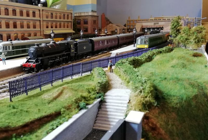
The view from over the tunnel entrance.
Above photos updated - better quality - night-time shots to do.
And a couple of "night-time" shots.
There's a couple more photos in the gallery - some are a bit lop-sided (but that's life!)
So while I've been off my feet I've spent some quality time with programming for the layout signalling - no signals yet installed - but there's now a program to work them!
Hopefully soon I'll be trying to get some "loco running" going around the layout (I keep saying that) - but I seem to be always building something or other - even down to recently renovating my ancient Class A4's motor (circa 1980-ish & of sentimental value) which, thankfully, is running somewhat better now.
With the Terminus nearing completion, the rest of the layout is looking a little bare in comparison and in need of some scenery work - and some signals!
Will I ever run the trains?
 Last edit: by Dave C
Posted
Full Member
The weather has been so good recently, we've taken the time for a couple of weeks away on the south coast, some gardening, general lazing about and not a lot more. Train-wise, very little has been happening. Having said that….
About the highlight(?) of the past couple of weeks of very short-lived and occasional activity has been making a start on installing the colour light signalling and the associated sensors around the layout. Perhaps I should have thought about installing the sensors in the lower, hidden sections of track BEFORE the upper level was put in place above it. But, as usual, planning to that level of detail is not my forte. As a result, it's now rather difficult to find where to drill the holes from underneath the boards to match and align with the track centres above - but I'm getting there. No-one can see the havoc that's being created in the dark underground caverns of the hidden tracks! What makes it worse is that the holes need to be almost square in shape (6.4 x 4.9mm) so some degree of filing out to shape is required.
The sensors will provide pseudo out-of-sight ("block") signalling so that those signals that can be seen will reflect a train's journey around the hidden parts of the layout and make the changes through red, to amber to green as if the signals were there - this is rather than use a timer between each light change. These pseudo signals will be viewable on a small mimic board even if the (hidden) signals themselves are not on the layout itself. And if a train does happen to get stuck, I will be able to see via the signals on the mimic board that didn't change state when they should have and have a good idea of the location of the train. It's all good in theory, but will the programming live up to the expectations? Here's hoping. It's part written. But getting the time to concentrate….
Previous to this I've also been making a (very) preliminary start on some scenery between the terminus and the Halt station - this includes a constructional test of a tunnel entrance, and ensuring there is a clear path between the across-track infra-red transmitter & its sensor only a couple of inches inside the tunnel.
For the making of the tunnel portal I followed the "How To" from marklinofsweden (Model realistic Tunnel Portals). For the styrofoam cutter I had some old resistance wire from many moons ago; at long last I've found a use for it! Hooking up a length of it to my spare PC PSU (+3.3v line) it cut (or should that be melted) easily through some polystyrene packaging foam being used as the test portal. So that - at least the theory of it - appeared to work just fine. So a jig has now to be built to cut slices of the Styrofoam for the portal itself. And then simply (sort of) follow the instructions in the video. The existing tunnel entrance was quickly knocked together to test out marklin's methodology of cutting styrofoam and to see what it came out like. As it is, I don't think it looks that bad really.
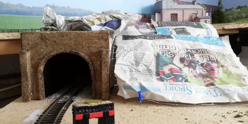
So I now have a (scrappy) section of hillside made up from some old chicken wire as the hillside former. At some stage there will be a (proper) layer of newspaper and some plaster bandage to cover it followed by ….. etc. etc.. At least there's some planning - and progress - going on here!
So, at the moment, there's the signalling in progress and the tunnel/hillside to complete. Nothing too grand to show, but a start has been made away from the terminus.
Posted
Full Member
As mentioned in the last post, I've been doing a bit more work on the programming for the signals around the layout - not fully complete yet though but well on the way. I've not finished the code for the Terminus exit yet - that's for another day, though I have made a good start. If only I'd stop changing my mind on the method of coding! The pcb layout keeps having to change as well due to the processor output pins keep changing.
This coding lark has not been quite as straight forward as I might have thought! - what does go straight forward these days? Simple enough if it's just one simple signal followed by another - but add a few points and a couple of other options into the mix and it opens up a whole new bag of worms trying to make sure it all operates as it ought and to only signal trains as and when appropriate for their safe passage. Interlocking I think they call it. And this across four processors controlling it all and they each need to interact and cooperate with one another. Four are needed due to the number of input and output ports required. There's still some way to go on this part of the project (fundamentals like installing the signals themselves and getting the sensors in place) but I'd like to get some signalling up and working before I go too much further - I like a bit of automatic interactive animation.
As a result of a few spare ports on one of these processors, I've now got the option to add another mimic panel that shows, not just the signals, but also track occupancy in a similar fashion to the wall-type displays seen in the more modern signalling centres. The occupancy detection not using current sensing circuits - just the passing over one sensor after another. Just an idea at the moment, but you never know. Another change to the coding!
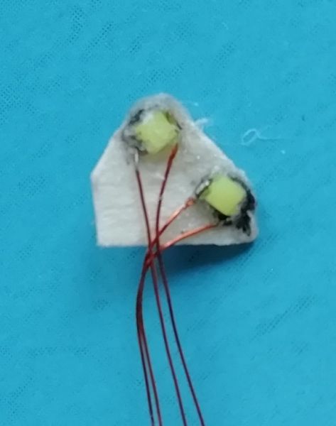
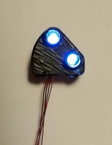
A few posts back (#56 April 2018), I mentioned I wanted to fit some positioning signals to allow for shunting movements towards the turntable and sidings - but this idea was at that time unavailable, at least at reasonable cost (i.e. they were far from cheap!). Time has moved on and thanks to easily available 3D printing, one company out there has produced a two-light (ground) positioning signal which looked to be ideal for my needs - no lights, only dummy heads, but they should be easily modifiable to accommodate some very small SMD LEDs.
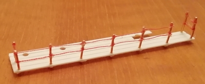
That's what I've been doing over the past day or so - starting with a coat of black paint, the making of a card insert to hold the LEDs and the gluing onto the card of the LEDs - very fiddly, especially with my fingers! A back still needs to be fitted but I think it will look the part - the camera on a close up shot shows every little flaw but when mounted in situ and viewed from a normal distance it should look good.
That's the first, quite a few more to do (when time permits).
Posted
Full Member
So over the past few hours I've been in reminiscing mode after looking back over some old photos taken over the past year or so. It was back in mid 2016 that my old Langley Junction layout felt the start of its demise with a new layout plan in the design stage.
Many months later, after much cussing at the struggling to get the old layout dismantled, the new structure started to take shape; from the initial track being laid (mainly thinking of the terminus area here) looking all bare and forlorn compared to what it is today - more or less complete (after a few changes to its layout along the way) and now with platforms, buildings, ballast, people, approach road with traffic, etc. It still needs Starter Signals to be put in place, but Rome wasn't built in a day. Neither was this layout!
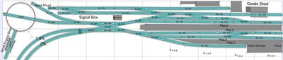
From the original AnyRail 3D design (above) to the printed layout itself in 2D:

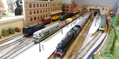
And this is what the Terminus eventually came out to be:
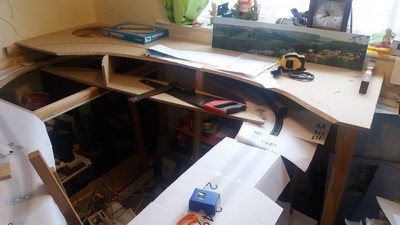
Some of the building work prior to the Terminus track being laid - this shows the start of the upper layer with the Turntable to the left and the start of the hidden section running underneath (post #19):
And eventually the trackwork was put down (post #41):
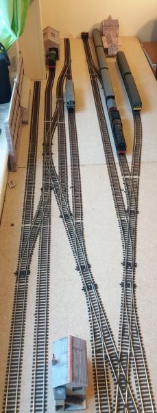
….. it eventually came out as (post #102):
There have been one or two other areas that have been worked on, such as the short disused spur disappearing into a boarded off tunnel entrance and also the turntable and engine shed area.
And there's plenty more to be going on with - as soon as I get round to it. Perhaps with the onset of the autumn months I'll get started again.
The priority being the signalling around the layout and across the Terminus. Then I can think about building up the scenery that will hide the "hidden" lower sections of track.
Forgive the bit of history, but it's good to look back and see how an idea turns out to be something that I, at least, can be relatively proud of. It's not 100% historically accurate, probably not even 50% accurate, but it's close enough for me! And maybe, one day, I'll even run the trains.
Enjoy the hobby.
Last edit: by spurno
Posted

Full Member
When I had a proper job I wrote training courses and in my spare time played with my model trains and did a bit of guitar playing/song writing.
In all 3 disciplines, what I started out trying to achieve always evolved and often for the better.
I think it is wise and rewarding to look back - if only to have a chuckle at some at some of the long-lost ideas we generate before finding a more enlightened path!!
Barry
Shed dweller, Softie Southerner and Meglomaniac
Posted
Full Member
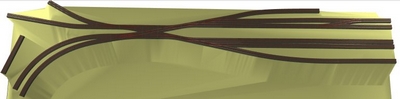
I've had a look around the plant ID sites and can find nothing that I can put a name to this plant. It's quite bushy and stands (if supported) at around 4foot tall - that's just over 1metre for the younger folk brought up on such nomenclature! So, if anyone has any ideas on a name, I'd be pleased to hear one or two.
The first photo is of a few cuttings straight from the plant/bush; the second is after the leaves had been stripped off; and the third is of a cutting taken last year (still bare and not touched). Hopefully, I'll find some time to add some foliage and some thickening of the main trunks later in the year and I'll put another photo or two on here at that time.


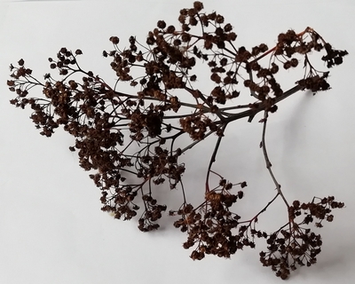
I think these will add another dimension to the layout and in addition to the buddleia flower heads previously used.
Posted
Full Member
I too am in catch up mode just now, as the weather ‘improves’.
Totally understand this ‘mojo’ problem, everybody seems to get it at some point. Mine took a bit of a battering earlier this year of course, and is still not exactly firing on all cylinders. Again this hot weather hasn’t helped, my grey cell just shuts down, firing it up again always takes a long time.
I don’t think I’ll be doing a reminder on Woodside any time soon, a quick review of progress since I joined the forum wouldn’t be much of a read!
I really am very envious of folk who can produce a ground signal, just like that…. I’ve been looking at the DCC Concepts offering, mainly because I’d like to get some signalling operational at Woodside station, the more working the signals on the layout, the better. They aren’t cheap, but bulk packs are more reasonable. The original thought was not to use any colour lights at all, I think Woodside remained all semaphore until closure, and do the whole station with semaphores – but that could well be a step too far for my limited skill set. Apart from it taking forever, I am still pondering on getting disc signals operated by w-i-t and just where all the w-i-t is going to fit, so the colour light option starts to look very attractive… and after all, I’ve already used a colour light with theatre box on the approach to Woodside, although that was originally a precursor to a full gantry… Perhaps I’ll give it a try… could be yet another winter project…. to add to another list….
You have done a great job on the lighting for John Street – for me, it adds an extra dimension to a layout, obviously visually, but also operationally.
Your new plant looks interesting, I’m afraid I can’t help with the identification, but I know someone who possibly can…. I was thinking about our Lilac bush/trees earlier in the year as suitable candidates – but unusually they didn’t manage to produce much in the way of blooms this summer.
Keith
Do I have a plan? Na, if I did I'd spend most of my time trying to remember where I put it.
Posted
Full Member
Thanks for your comments, appreciated as always. Glad you like the night-time shots; as you say, it gives an added dimension. Only problem is, in the darkness, you can't see what's going on or where anything is on the layout unless locos and coaches have lighting - and that's a step too far for me at the moment.
Like you, I like to see working signals. Langley Junction had one or two semaphores but I found them not to be too successful. A bit fiddly to put together and get operational. Hence, John Street is all colour light signalling.
I've been looking around at ground signals and there seems to be - on the colour light side of things - the TrainTech items or those from Eckon and some new offerings from DCC Concepts - but as you say, all at quite a price - good quality but the price is a bit high for me. (I like "cheap"!). Those that I made up were bought from the normal web market place selling site from a company called 3Dprintingcorner (based in St.Neots). They are only dummy heads but with a little dexterity and some patience (both of which I have in very short supply at times), some SMD LEDs and a lick of paint they can be made to work - but they're only two-white-light units, as shown in my post above. Definitely fiddly to put together - that's why I've only made the one, and I need another 6 at least.
On the mechanical ground signals front, there are those from Ratio. Not sure if they can be made to operate, but again, with some ingenuity, I'm sure they could be made working.
I also spotted some ground repeater signals that reflect the red/yellow/green of the main signal. These are from DCC Concepts and I also found some coming from China.
So there is a fair selection out there, depending on which way you fancy going.
Incidentally, I ought to note that I have no connection with any of the companies mentioned other than as a purchasing customer who likes to have a good look around to see what options are available to us, the hobbyist.
Regards to you Keith…
Dave
PS The mojo is more-or-less back; regrettably available time to make use of it isn't!
Posted
Full Member
At last! I've started to get back into the swing of things and beginning to get some enthusiasm back now that the weather has turned rather cooler - and wetter. Once again, it appears I've gone slightly off the current and the to-do-lists.
A couple of lengths of "brickwork" have been added - but not yet fully completed - across what can now be regarded as a viaduct before the line dips under the Terminus. So there goes my small workbench that used to sit over that stretch of track! It was becoming a bit of a dumping ground (much like any other available space!). I must soon get some ballasting done along here before long. That's another item on the (one of many) lists!
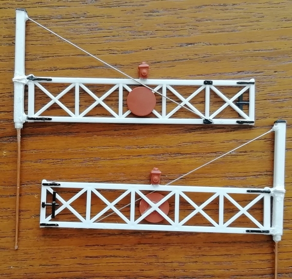
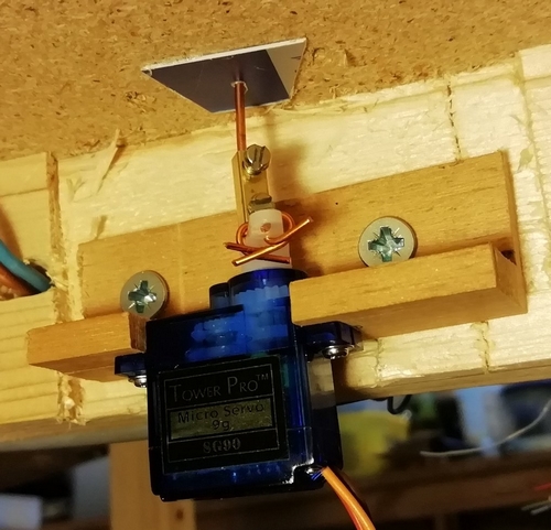
Also, and this has taken me quite some time to sort out, I've taken to making up a pair of automatic level crossing gates. A bit of a fiddly job to get an old and dismantled pair of gates back into something that would likely work - the gates had been used previously (as static items on the previous layout) and which were now broken away from their main support posts and with other parts come adrift as well.
These problems were overcome by using some thin wire and a blob or two of glue to hold it all together again; and then overpainted to camouflage it all! A hole was then drilled up into the main support post to hold, once glued in place, a length of 1mm wire (from redundant household twin&earth wiring) that attaches to the servos that makes the gates turn.
Holes were then drilled into the baseboard to pass these wires through with the servos being mounted directly underneath. Before the gates could be fitted, there was the necessity to get some scenic and ballasting work finished in that area (didn't want to run the risk of damaging the gates - again) seeing as how I'm getting so cack-handed these days.
The following picture shows the linkage between a gate and the servo and also the servo mount itself.
The next, and the main problem was to program the PICAXE chip to operate the gates. The gates are triggered by under an track sensor so that the gates will open according to a train approaching and operate the "guarding" signals correctly via the signals processor and not to close until the track is once again clear. And that programming turned out to be a job and a half! Sounds quite straight forward, but adding in the prospect of traffic reversing into or out again from the siding complicated matters, as well as the possibility that the gates might need to be kept open due to a second train approaching. It just seemed to snowball. It all seemed to work fine - at least for the first time through the sequence - but then didn't re-open the gates. After much head scratching it turned out to be an "interrupt" command that works only once in the routine and I'd forgotten to add it back in ready for the next approach pulse. Always useful to remember the write-up in the manual for each command being used and the effects of each command. Either way, that command has (at this time) been removed as redundant. And then there was the open and closed gate positions to accurately get correct - not that easy when you have a dodgy servo. The gates do seem to judder a little but this is more down to the thin plastic nature of the gates coupled with the pulsing of the servo rather than any thing else. Otherwise all working fine now (after replacing the suspect servo that kept losing its position) for the main line but modifications will need adding for the siding movements.
When I get back to finishing the programming for the signals, I'm sure it will all come together - eventually.
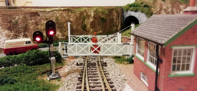
A bit more ground-work is still needed around the signal box, but we're getting there.
Right. Back to the signals programming. Hopefully I can now get this completed and the signals and sensors in place. More to follow….. Hopefully I can get back on track and follow the to-do lists (of which there are many!).
Posted
Full Member
"Very" while testing under varying circumstances! A fast running train and all worked well - gates opened and then closed following the train's passing. Brilliant. Just like in the simulation mode on the laptop.
But. Send a slow moving train through and the gates failed to close after its passing. Seems like it was double registering a counter/marker if the first sensor was passed at a certain point in the program running or if the train was reasonably slow running. That issue took some finding especially as the command is only supposed to be active for a "one off" pass and then ceases to be effective. The command being SETINT, for those that know the PICAXE BASIC programming. For some reason, it appeared to work twice within the running loop which waits for an interrupt from the sensor it was watching.
Add an additional command and all is well irrespective of the speed of the loco.
But I do still need to do some testing and, most likely, some additional programming when the siding is in use. That's a known fact and doesn't faze me - I just needed to get the basic through-running up and working correctly.
In between times, when I've been able to get into the 'train room', I've had problems with a voltage comparator chip that interfaces between the sensor(s) and the processor for the gates. It suddenly decided to play silly so-and-so's and the circuit had to be effectively rebuilt after being unable to figure out what was going on. While messing around here, I also decided I needed a bit more infra-red light for the across-the-track sensor. A change of resistor here and now I get a good bit more light received on the other side of the tracks. In the process, the current through the emitter has been up'd from 20mA to 35mA. Hopefully, this is still within the specification for the device.
I still have another issue for which I am looking for some advice. This is related to the gates and their flexibility and the fact that the servo is a pulse driven stop/go mechanism and it's this that's causing the gates to flex and flap while moving.
I'm wondering whether glueing a length of thin piano wire about 0.5mm dia (or maybe 1mm) - or maybe even brass wire - along each gate's length would be enough strengthening to stop this flapping about. The servos themselves seem to operate smoothly enough but when slowed down for the gates to be of a realistic speed the outside edge of the gates flap. Annoying!
Anyone have any ideas or suggestions on this?
Cheers
Dave
Posted
Full Member
My mind has now turned back to getting some signalling up and working. Again, I am looking to something being as fully automatic as possible. But before going too far, I decided to build up a Signal Gantry to be located at the top of the loop section prior to the Terminus Home signal. No space for individual post-mounted signals, so the gantry was the way to go.
Having watched the excellent Charlie Bishop video (Chadwick Model Railway - Chadwick Signal Gantry) on modifying the Ratio 478 Signal Gantry, I thought this might be a good place to start for ideas. I didn't want to extend the gantry as in his video (but which I will do for the Terminus gantry) but to reduce its overall width to suit the space available to me.
Digressing slightly, one thing I noticed when buying a new pair of Eckon/Berko signal heads is that these heads now come with only ONE return wire to ground in a fully enclosed moulding - this is new, it is to me at any rate. One signal was going to be a 3-aspect RYG, but this I couldn't fit within the signal gantry kit and as the next signal - the Terminus Home - remains at a red aspect until a train gets close to it (prompts a slowing down of the approaching traffic) these signals will never show a green aspect; so these two signals are now 2-aspect red/yellow. This has led me to reconfigure the wiring to these two signals; previous purchases had two return wires that made feeding power to them a bit more flexible and made using them via a ULN2003a driver chip easy - now that method is dead in the water! So it's back to feeding these two signals direct from the PICAXE and the mimic signals as previously planned via the 2003a. Each PICAXE output is only capable of supplying around 20mA - not enough to drive more than one LED.
Now I'm off to start the construction. More on the Signal Gantry in the next update.
Posted
Full Member
Not being entirely sure of what I was about to attempt (despite Charlie's video instructions) I started off by photographing the plastic moulding and then printing it actual size onto an A4 sheet. This was mounted onto thin cereal box card to give it some strength and the bits were then cut from that and the "gantry" was built up from that. This allowed me a couple of times to try out various cutting options of the cross girders/beams and seeing what configuration of cuts best fitted the layout without the possibility of wrecking the moulding itself from a poor decision being taken.
The girders needed to be shortened by two sub sections which meant that in order to keep the 'X' sections central I needed to cut one sub section somewhere either side of this.
This completed, the sections were cut and re-joined and with the cross-bars cut away for the signal heads a length of rectangular tubing was glued into position as though it was a walkway for any maintenance crew; it was in fact there to hide the signal wires. A walkway complete with railings was then constructed and fitted to the rear of the gantry.
A few more additions and it's just about complete.
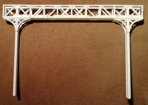
A fiddly job which somewhat diverted away from Charlie's excellent description. A quick coat or two of grey primer completed this part of the construction. Then in went the signal heads and the wires pushed into the trunking sections and down through the baseboard and this more or less completed this part of the project. Only the ladder remains to be fitted from its temporary position.
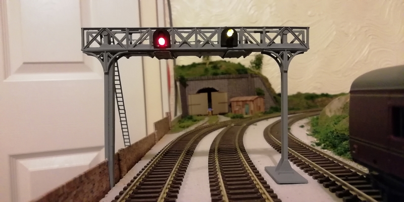
The signal heads are from Eckon/Berko (BH02) and they fit nicely into the front moulding - a Yellow/Red aspect here as the next signal in line will always be a Red until a train approaches (this to assist in the slowing down of traffic before entering the Terminus), so neither of these signal heads would ever show a Green aspect should that aspect be available. Overall, I think the job looks a good 'un. Looking at the photo above, it looks more like a green aspect rather than the yellow - but that's the camera for you.
All I need now is some ballasting and to wire the signal heads back to the (yet to be built) processor board and finish the programming then I can start installing the remainder of the signals before starting to think of elsewhere to work on the layout.
Posted

Site staff
Ed
Posted
Full Member
Yet I keep on slowly adding bits of programming for the signals, but each time I put it down for more than a few days, I seem to lose track of where I was and what my thought processes were at the time (despite copious notes) - and newer ideas come along which means I tend to mostly start again.
Looking at the overall picture, I seem to need 6 processors to do the job I'm looking to achieve - and for such a small layout even I'm a little in disbelief:
There are two processors that look after the Terminus (one for the live departures, one for controlling access to the sidings) - a distinct lack of available ports on even the biggest processor available to me,
one to look after the first half of the layout signalling,
another to look after the second half,
one to control access to the Terminus and to indicate which platform will be accessed and
a separate processor to operate the Level Crossing.
The reason for so many processors is that there are so many input and output ports that are required - which has lead to duplication of input ports between some processors, such as which terminus point is set to which direction and which can only allow (from a signalling viewpoint) a movement in that direction.
Checking across the layout, there are 14 points to be monitored, 16 signals (a mix of 2 and 3 aspects - 45 aspects in total - some are in hidden areas but nevertheless will be reflected on the Layout Mimic Panel), I think 11 track sensors, a Home Theatre Display and a Level Crossing (it still needs to monitor and be monitored). And each processor relies on the next processor in line (with two exceptions and which can be regarded as standalone but are still monitored). Many of the signal aspects are single or dual output with the missing aspect derived from basic logic chips. No doubt, it could all be done with, maybe, one less processor but the processing power (speed) would be rather reduced as more code is added. Anyway, that's the way I've decided to go - for better or worse. I have to take my hat off to those that have to program for the real railways that run to a real timetable.
And all this lot is taking time to get right. I've still got to install most of the signals onto the layout, never mind wiring them up to the electronics! And the Layout Mimic Panel has yet to see the light of day! It's there on paper, but that's it.
Anyway, we keep progressing on - one day the programming will be complete and I can then sit back and enjoy some visible activity on the layout keeping in line with the movement of the trains. I don't mind admitting it, I like signalling that works and with as little interaction on my part as possible (it takes too much concentration to deal with the loco movements on a small layout such as this without worrying about signalling being correct!).
Right, back to the drawing board…..
Posted
Full Member
That’s an awful lot of programming! I can appreciate when it is all done the finished article will be mighty impressive. It’s refreshing to hear that it’s not just me that forgets the thought processes I was following between sessions working on the layout – and I don’t have any notes to refer to.
I’ve bought some 3 aspect Train-Tech signals together with their ground signals for Woodside – not too expensive, and being in ‘kit’ form, should be easy to ‘modify’ if required. Just finding the time to get it done is the problem, but at least they’re on a list and in a box now!
Trust all goes well with the programming, and may any bugs be easily sorted.
Keith
Do I have a plan? Na, if I did I'd spend most of my time trying to remember where I put it.
Posted
Full Member
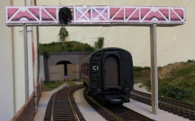
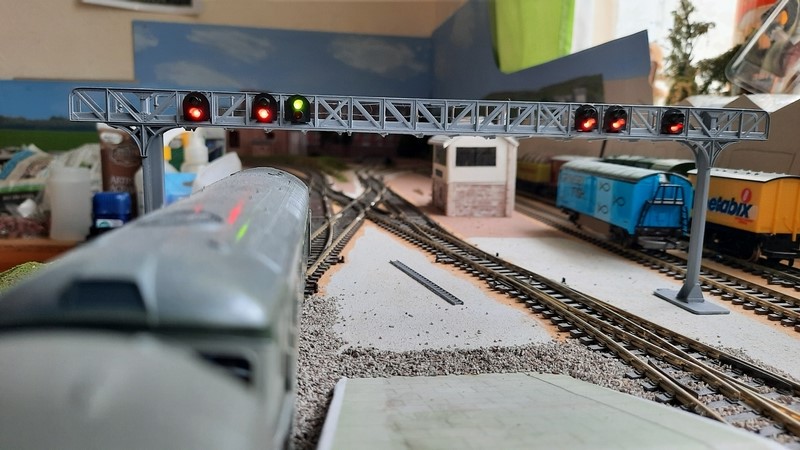
It's taken quite a while and has been based upon the success of the previous Gantry on the UP line (with the passing loop) - below.
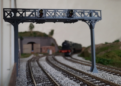
Earlier signal gantry on the UP line, now with ballast in place and a light Class B17 61663 "Everton" rounding the curve coming down from the terminus with the disused branch line bending off to the left. The gantry signals are currently unpowered as the signals processing still need completing and connecting up - but we're getting there.
So, with this complete, we've been one step nearer to the completion of the Terminus Signal Gantry.
Based upon that earlier success - and in between sessions of programming - I've built up this second signal gantry to be at the exit throat of the Terminus - this time much wider and comprises two of the Ratio 478 kits 'stitched' together so that I can have six 2-aspect signal heads mounted on it. I had wanted to have some position signals (post #104 shows the internals of these small devices) also on the gantry but space didn't really allow it; so they are now going to be ground mounted. Construction for the gantry was largely the same as that used in the earlier (and smaller) version. Again, thanks go to Charlie Bishop at Chadwick Model Railway for the idea and construction tips.
To overcome the possible struggle of getting all the (supplied) wires of the 6 signal heads (24 of them) into the small tubing used to "hide" them, I swapped the wires for thin 30swg enamelled copper wire with only one positive voltage connection to each signal head - it's the return (ground) wire from the individual LEDs that go to the ULN2803a driver chips. These chips pull the voltage on the LEDs down to 0v (via the usual 1k limiting resistors) so a common +12v was wired to each LED. The wire count was thereby reduced by 6 wires making life somewhat easier. And it worked nicely - still a bit of a struggle though.
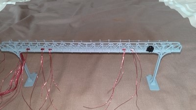
Getting all the wires into the trunking ready for the LEDs/Signal Heads. Platform 6 signal head in position ready for connecting. The wires pass down through another length of trunking (not yet in place) and through the baseboard.
All has been temporarily powered up to show the aspects with a Class 33 departing from Platform 3. More photos on this gantry are in the photo gallery.
All I need now is to add the ladder, fix it all to the baseboard, add the ballasting and some final touches, such as the signal numbers. Then I can hook it up to the processor board together with the remainder of the signalling and sensors. And maybe I'll get the processing finished and it should then work as intended.
I need to keep reminding myself that Rome wasn't built in a day - neither was this project!
Posted

Full Member
It's a great feeling when something gets finished. Like you, my layout seems to be taking an age!
Michael
Last edit: by Headmaster
Posted
Full Member
There's enough to be done, more than enough - maybe that's the problem. I want it all doing - now. So, as I've not posted anything for a while, I thought I'd give a short update on what little I have been doing.
It's good we all can have differing priorities with our layouts. Mine basically runs OK; there's a few bits of scenery here and there (nothing fancy) and the Terminus is done (no doubt with a few minor additions yet to come). But my passion at the moment is to get working automatic signalling around the layout. Thankfully the layout is a fairly simple "out and back" design. Once out of the Terminus, it's straight forward(-ish). The Terminal itself, and its sidings, are giving me a bit of a headache.
It seems I've hit a bit of a block with the programming for the Terminus signalling. I need to use two processors due to the number of inputs and outputs needed (around 45 - each processor can only handle 32 I/O lines) and the way I've been trying to program them, I was very likely to get some issues between them as they tended to work independently. So a total re-think and a different approach is being adopted - and that makes use of, something that is totally new to me, the I2C communications protocol to link together 2 (or more) devices. It also means I can't run the "simulation" part of the programming program to test it out. Maybe this protocol could lend itself to linking the other processors for the main layout signals as well - food for thought. Depends on how many spare I/O lines I have left to play with.
A start has been made to it using odd bits of code from the previous incarnation which did work (on simulation) and which can still be tested in the new environment. The link between the two processors regrettably can't be tested to test the two halves working together; but I'm sure I'll find a way to get around it and simulate the effects of the link.
I still fall foul of the keep getting side-tracked scheme of things; that and making "to do" lists. I've since created a new list - there's only one item on it, "stop making lists"!
 :shock:
There's been a bit of scenery/hillside added just out of the Terminus. It's only got the initial coat of brown at this point. That's something else that needs finishing off once I get the signalling working - that's the priority now.
Right, I'm off, back out into the sunshine; might as well take advantage while it's there. Catch up with you again soon, hopefully with something more concrete to report.
Posted
Full Member
Then I again regurgitated the code and started again. I got quite a long way into it this time and then …. This time I've now come up with a scheme that interlinks a number of processors with something known as I2C comms (new to me!) so that each input (sensor or point setting) doesn't need inputting to each processor - they get 'communicated' between the processors that need to have that information. If nothing else it'll save a few input ports for these processor inputs. Now I just need to learn more about the I2C comms and then to get the code re-written (again!).
Yet again I got sidetracked following a recent post by Keith at Woodside and the photo of his semaphore signal. It made me a bit nostalgic for those structures - I've gone all colour light signalling on this layout. But, even now in the real world, there can still be seen a mix of colour light signals and semaphore. So I decided to look into resurrecting a signal from a previous layout (Ratio 486). Problem is, it's a bit too wonky for my liking so a new purchase was made along with thoughts on if and how it could be incorporated into my automatic signalling.
Anyway, that aside - item ordered and sitting there waiting for be built. Something for another day.
So, for a while I've been trying to get a working level crossing sorted out. All fully activated by approaching trains and so on. But there's a problem with it.
I've motorised the gates using small SG90 servos and the problem is - and it's probably more to do with the plastic nature of the gates - the gates themselves seem to vibrate/shudder as they open/close. Most likely it's the way the servos work; getting them to operate at a relatively (realistically) slow swing speed the servos seem to jump from one position, then pause before making the next small movement.
I'm not sure quite how to dampen this vibration down to make the movement appear smooth. Maybe even simply adding some piano wire to the underside of the gates to make the gates less flexible would work. Or I guess another option would be to use more normal dc motors (with numerous gears) and some hall effect switches to mark the start and end of each gate movement. Or use stepper motors that only need a known start (closed) position before counting the number of steps to the open point and then counting back and forth again. But would this 'stepping' action again produce a similar shuddering of the gates? Maybe not in such a (vicious) manner as with the servos.
Something to think about over the next few days/weeks while I work on something else.
1 guest and 0 members have just viewed this.