Deeley 0-6-4T "Flatiron"
Posted

Full Member
A restoration
:cheers Hic!
Good reinforcement of the cut both parts together tip. Works with bridge arches too, as long as the bridge is square on to what it's crossing :roll:
The horn blocks and compensation system makes my mind boggle.
but I'll watch and learn.

Posted

Full Member
John
John
Posted
Full Member

These are etched longer than most prototypes and need to be trimmed to length. First though, deep breath and spend a few minutes studying the fret and pictures of your loco to make sure you get things the right way round.
After an hour or so I ended up with these:
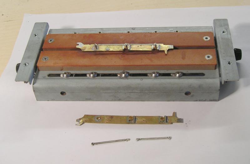
Fiddly job of course, the rod halves are soldered together with the rod pivot representation overlapping in the middle. Everything is carefully filed and fettled and checked.
Rods are very critical to the smooth running of your chassis, their centers must be EXACTLY the same as the bearing centers. This is where the jig comes in very useful.
There are cheaper ways to do the job. I recommend the DVDs Right Track Nos 1 & 2 hosted by Tony Wright. These showcase the build of three kit locos and, while a bit dear, are around 3 hrs long each. You'll need to check the second hand market I'm afraid since they are sold out.
Another excellent resource is Iain Rices' Loco Chassis Construction. It is out of print but you may find a second hand copy. I built my first chassis (the ubiquitous Pannier tank) by following Iain's lead in the book. An added bonus was that it worked too! I also learned a lot about soldering.
John
John
Posted
Full Member
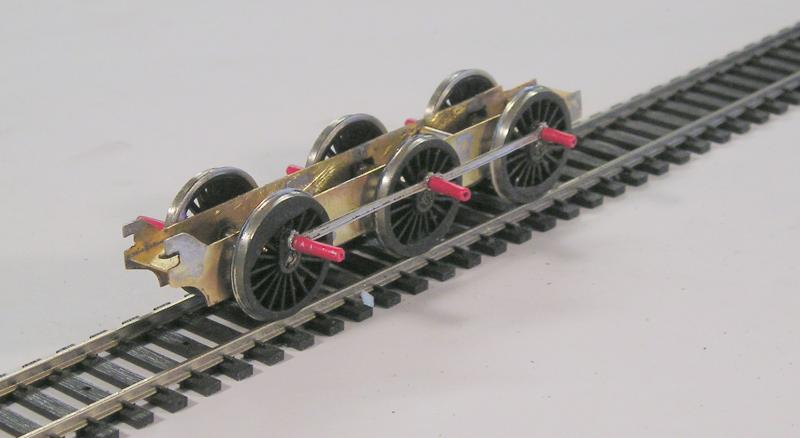
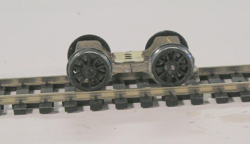
So, over the last several days, I primed the wheels with metal primer, left that for a day or so, then sprayed on Testors matt black, leaving that a day.
A couple of days ago I used my jig to join the two frames.
Today, I brought it all together:
Scraped paint from the tyres, and polished with fiber pen. Checked for insulated vs uninsulated wheels and paint the back of one spoke of each insulated wheel white. You cannot tell which is which by looking and it is very easy to get it wrong (don't ask me how I know).
Ream the chassis bearings just so that the axles fall through by gravity.
Here it is:
This is from the rear.
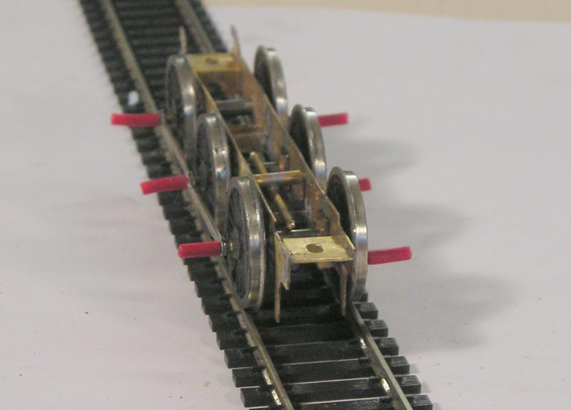
…and from the front.
The red tubing is wire insulation. This makes it easy to remove rods for hole reaming to get the chassis rolling smoothly. This took a few tries and it's good now.
You can clearly see the compensation beam soldered to a tube pivot and resting on the middle and front axle. The rear axle is fixed and will be driven.
John
John
Posted

Full Member
Paint stripper (the "Green" or "Eco" variety), or a mixture of methanol/methylene chloride or methanol/paint thinner. Dunk the model in and leave it. It may take a week to a month if the epoxy is of a good vintage. As a bonus it gets rid of the paint. Use a metal sieve to collect small bits. Vinegar (white, not malt) works as well, although I've never tried it, except for pickling brass.[user=6]Petermac[/user] wrote:
How does one dismantle a body glued with epoxy John ?
Carefully Peter, very,very carefully….or dynamite.
Heat gun helps as well. Not for white metal though.
All the second-hand metal kits I buy go into the paint stripper for a rebuild.
Nigel
©Nigel C. Phillips
Posted
Full Member
I agree Nigel, I think I've said it before, if you buy a second hand kit built loco, be prepared to rebuild it. If you want the thing, you'd be better off buying the kit - this would save the time and effort of tearing it apart before starting over.
John
John
Posted
Inactive Member
Posted
Full Member
John
John
Posted
Inactive Member
 Last edit: by 60019Bittern
Posted
Full Member
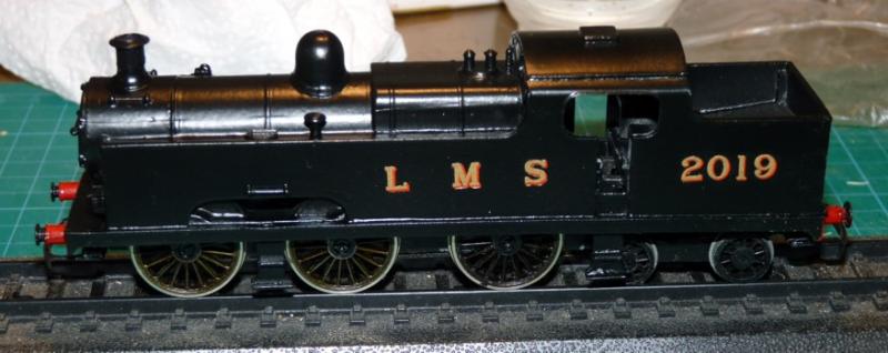
In LMS times, livery was red until about 1927 when it was changed to black with red lining, so that's what I'll do - hate lining though.
My references:
LMS Locomotives Vol 4 and Midland Record which has a lovely article on these. The article has a reproduction of a works drawing. Unfortunately, it only covers the MR era and doesn't get into the LMS history. There was a water scoop I learned.
John
John
Posted
Inactive Member
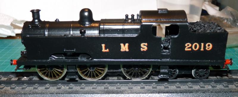
Some time in the future I might well strip the paint, replace the chimney and repaint and letter it. Might even get the lettering straight the second time around. Oh, and fit some cab handrails.
Last edit: by 60019Bittern
Posted
Full Member
Probably worth getting on with something else for a while. Too much time spent on one project can lead to frustration and loss of drive.
John
John
Posted
Inactive Member
Posted
Full Member
John
John
Posted
Inactive Member
Posted
Full Member
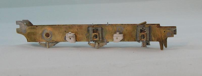
From the drawing, the bogie has a 6' 0" wheelbase - this matches the W/M bogie.
I want to use a Comet bogie but the closest they come is 6' 3", only 1mm out but I will correct it. Here's how:
First I mark out the fret with my scriber for centerline and where I want to axles to be.
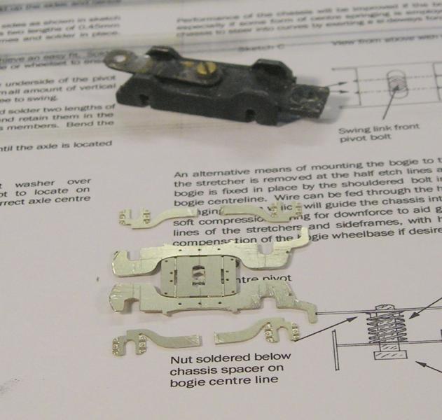
I think you can see the scribe lines. The frame slots have been widened by 1mm. I've cut the overlays and shortened by 1mm. The frames also get shortened by 1mm.
Next, I solder the overlays in place being careful to get the inner slot to align with the inner slot of the frame.
Next fold everything over and solder. Fettle the slots for the axles, slip the wheelsets in and retain with 0.45mm NS wire through those holes you can see in the bolster.
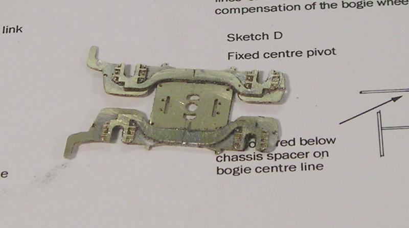
The finished bogie. The drawing shows a leaf spring but it appears to be behind the frames and is not visible. Actually I still need to open up the slot in the bolster.
John
John
Posted
Inactive Member
Posted

Full Member
It's looking really good John although for now, I'll let the likes of Hornby and Bachmann have the headache of "fettling" ………. Maybe when I'm a bit older, and one heck of a lot wiser, I'll do my own ……….;-)
'Petermac
Posted
Full Member
The thing of it is, Hornby et al would, today, probably produce something with outstanding detail and accuracy and all you'd have to do is open the box.
Even so, it's nice to be able to overcome these hurdles and get something that is over and above the stock kit.
In fact, this and the MR 0-4-4T are two locos that I'm surprised none of the manufacturers haven't tackled yet.
John
John
Posted
Full Member
There are 'orrible great lumps of whitemetal that came off the original model. After I carved away the lashings of epoxy, they actually resembled sandboxes. However, upon comparing them to the drawing, they would have required a load of effort to get right. I figured it would be easier to make fresh ones from Evergreen strip - as you see. These were measured and scaled from the drawing. You can also see that I drilled and soldered some 0.032" wire into the frame to hang the boxes off. A much stronger joint. CA was used.
I also bodged up some leaf springs by carving and filing some NS scrap strip to shape. I had thought about using the springs on the original chassis but again, they look nothing like the drawing. A piece of strip soldered to the middle to represent the strap. 0.45mm NS wire was soldered to the back and fixed to the inside of the frames.
Now, the front axle, according the source material, has coil springs. (The 2P and 4P compound also have these). Quite a faff to make these. Basic material was 10BA brass screws sandwiched between NS strip.
It all looks a mess at the moment, but, as they say in the theater trade - "it'll be all right on the night".
John
John
1 guest and 0 members have just viewed this.