Finally, a New Layout
Posted

Full Member
Thoughts on baseboards
Hi John,I like the idea of dowels instead of screws. I shall give it a try on the home layout (scenic test track really) which needs increasing in width from 12 to 15 inches. Least metal the better. Although I did have a module that was put together with wood glue only. Survived numerous drops.
I must admit I take a slightly different approach to matching top t'bottom - the frame is cut to the top (using the top to set the table saw), not the other way round. Working with birch has it's drawbacks being 6, 9, 12 or 24 mm , translating that to 2 feet x 4 feet is not exact. A 4 foot length (or 3+5 for 2 linked modules) is essential in the modular world where it will have to match to another module (2 x 4 feet rules). Bit of leeway on the frame is OK at the sides and width, not the ends.
Nigel
©Nigel C. Phillips

Posted

Full Member
Lesson learned for non-standard boards like the two angled ones I have is that the top should be cut to match the frame. I suspect the frame is at fault but there is no going back now. The tops I have were cut a couple of years ago for another project that didn't go anywhere.
Not sure what you mean about the birch ends - mine is 12mm I suppose but matched with 1/2" standard ply which is on the outside.
You mention modular - is your club modular? When I first joined the Montreal club the layout was supposed to modular, ie any board could join up with any other. Despite standards being published and jigs made, the system never worked and was an ordeal to set up.
John
 Last edit: by Brossard
John
Posted
Full Member
12mm birch is a tad less than 0.5" (0.4724"). So, 2 feet wide, 12mm sides, that's 2 feet-24mm = 2 feet-0.945" for the ends and cross braces (if you have the ends inside the sides). Not the easiest length to measure and cut repeatedly. I use some sacrificial wood and set the saw blade at the required width, using the top and attached sides as the datum (measuring 23.05" requires 1/32 precision, which is 23" plus hand nudge territory). It's a bit trial and error and probably the only drawback of using metric and imperial wood in the same build, but once done the 2 ends and 2 internal braces can be cut uniformly. I'm tempted on the next build to use ply for the top, pine for the sides (1 x 4 nominal, 0.5 x 3.5 actual) rather than 12mm ply, and ply for the cross braces and ends.
Get the sides attached and it's easy to see if a cross piece is too long (use the sander) or too short (an "oh dear" moment, waste/spares bin). The module standard I'm supposed to use calls for 1" thick ends as modules are simply joined together using 2 C-clamps. No fancy locating dowels or pins, and no bolts. 12mm ply is an excellent substitute. Cross braces are normally 9mm ply.
The wood-working shop I use at the local community center ($12 the day, DIY) has a decent commercial table saw, balanced and supported blade, so run-out is minimal. Plus a professional carpenter to give advice/help/assistance. Invaluable.
Nigel
©Nigel C. Phillips
Posted
Full Member
I've assembled two sets of frames tonight and amazingly they are square. I'm very limited for flat work area and I put these together on the dining room floor - which is as flat as I'm going to get. Should get the tops on tomorrow and hopefully finish the final two by Monday. I've got loads of legs but some will need adjusting for width and height.
The only power saw I use is a jigsaw. Not the best I know, but the circular things scare me to death. I find a rasp to be a useful for smoothing cuts.
The old modular layout I mentioned relied on c clamps as well - no way you're getting to get those steel dowels installed with the accuracy you need. Track alignment is usually a pain. I guess you could use a piece of bridge track but it looks awful and they must wear and break frequently. Best to have boards assigned to specific positions I think.
John
John
Posted
Full Member
Once the boards are up, I'll take some pics.
I'll need to start a new thread on the layout itself.
John
John
Posted
Full Member
One of the joys of the modular world - bridge track connectors between modules is the standard, allowances have to be made for slight variations in track positioning (and ham-fistedness). There are ways to gussy them up, but most just stick in a section of bare track. My current effort is two 4' x 2' modules intended to be one unit, so I can use end-to-end track in the middle. Might put in a 4' x 1' bridge module between the two 4' x 2' modules (12 feet is a reasonable length for a passing loop and i have a 5' x 1' module going spare), we'll see.
That slight discrepancy between mm and imperial can come back and haunt you in the modular world.
I'm going to try the dowel method tomorrow, I built the frames sans screws, pretty sturdy (they withstand the 190 lb weight test, and I dropped one getting it out of the car). Belt and braces, as they're butt-joints.
Nigel
©Nigel C. Phillips
Posted
Full Member
For this layout only the first issue will be present since the track will be laid in alignment and that's how it will stay. My approach to end security is:
- glue copper clad sleepers (4 - 6 I'm guessing) securely to the board and solder rail to them (I have tried the brass screw method but, to me it looks pretty bad).
- no overhanging rail ends - make sure they are flush
- end covers for transport so that rail ends are only exposed to risk for a very small period of time
I'm pretty happy with my dowelled boards. It's more work than screws I think and there are many blow outs from the drilling, the worst of which require filler.
A bit confused, are the boards that you mention part of a modular layout or something that you are doing as a stand alone layout?
John
John
Posted
Full Member
I came across a product called "Gapmaster" (product #GM007) from American Tie and Timber (americantieandtimber.com) last year that is intended to replace rail joiners. Could be ideal for end of baseboard track. Looks to be CNC machined copperclad tinned and gapped, 4 sleepers/ties long. Nice idea if it matches your track (GM007 matches Peco Flex, probably too short for C+L).
I'm using this on the internal track ends of the modules.
Nigel
©Nigel C. Phillips
Posted
Full Member
Do let me know what you think.
John
Last edit: by Brossard
John
Posted
Full Member
I was thinking of sleeper/tie width/length if you are using C+L finescale OO track. last time I was at Hobby Jonction they didn't have them. I got mine directly. Postage is a bit steep for Canada. I won't be up until October, otherwise I could bring you some. It's a neat concept, get rid of rail joiners, which fits in with your comment on BigBob's post regarding droppers.
Still leaves me with the issue of bridge track though. The FreeMo people have a bridge unit that could be ballasted and into which the 4" rails were dropped (note rails, not track), although it was usually on back order. I just checked, it's now available (and improved) - bnm-hobbies.com is the source.
The major issue with all these bridge designs is that conductivity is usually dependent on rail joiners. Which have to be loose to allow easy attachment. The module group I belong to has cork underlay to the edge of the modules (but not the track). And 6 inch bridge units (a throwback to Atlas 6" sectional track I suspect).
Nigel
©Nigel C. Phillips
Posted
Full Member
I've found that postal charges from US are ridiculous. Far better to order stuff from the UK - cheaper postage and usually quicker. Plus I think there is a higher probability of CRA busting you for tax from the US.
Rail joiners have their uses - to keep rail ends aligned. I have some cast fishplates from exactoscale that I want to try.
The thought I had some while ago for bridge track was to make the thing as follows:
- piece of ply the width of the two tracks and long enough to form the bridge. Thickness to be the same as the underlay.
- lay the track on the ply and wire it to the main board. Probably want some means to secure it for transport.
- dowel the unit at one end to give it a small amount of adjustment.
- ballast and titivate.
- probably still need joiners to ensure rail alignment.
Of course this assumes that the track on the two boards is not too badly out.
Anyway, I'm curious to see what the trade has to offer.
John
Last edit: by Brossard
John
Posted
Full Member
That should work. I've done it with a piece of cork underlay with the bridge track on top, ballasted, etc. Electrical connection through the rail joiners (the weak point). If the bridge track is heavy enough stud contacts underneath work. However, this works if the other module has a space for the underlay. Chances of that? Snowballs. I shall be stuck with track bridge units. I suppose I could take a bit off the ties and glue some 0.01" styrene to support the ballast. It's possible to have a 6' piece of track, spray with canola oil, ballast using PVA, and remove the track just before the PVA sets up. Or use styrene strips cut to tie dimensions kept in place with double-sided tape and ballast in between.
Finished up the first 4 x 2 foot module this afternoon, I used dowels at the end joints and at each brace. Internal pine blocks at the sides of the butt joints. Looks nice without any screws (except for the top, where as you know I screw and don't glue). Total weight is 17.5 lb (12mm frame, 9mm top and 2 x 9mm internal braces at 16" centers with holes for wires). Second one should be finished tomorrow.
Dowels from now on! Thanks for the method.
Nigel
©Nigel C. Phillips
Posted
Full Member
Glad you like the dowel method.
I was wrassling with my boards for their first fitment. Not too bad but fettling is required methinks. Trying to get things level on a carpeted floor is a bit of a challenge. Good news is that the boards are not all that heavy, not featherweight but manageable.
I've been going through my MRJ collection for track plan inspiration. It is pleasant to go back in time. It's a cardinal sin to build the boards before having a plan for the track.
I hope you do some posts on your club layout.
John
John
Posted
Full Member
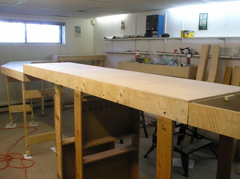
The main layout (whatever that is) will be on the foreground boards.
The three lower boards will feature an embankment and some pretty scenery. I'm thinking a canal, road and pub (how original). The angled boards will get a curved front by means of high density foam.
The furthest full height board is to be the fiddle yard.
I reserve the right to extend the full height trackage onto the lower boards depending on needs. Since the fiddle is only 4' long, to maximize train length, I will begin the ladder on the adjacent board.
The nearest board to the camera doesn't have its' top yet. That's because I'm undecided. I was inspired with Nicks' Much Murkle and the fiddle yard behind the scene. As I mentioned, I'm going through old magazines for further inspiration.
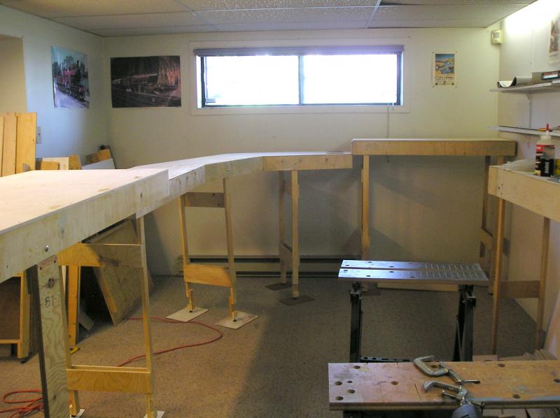
Taken for t'other side.
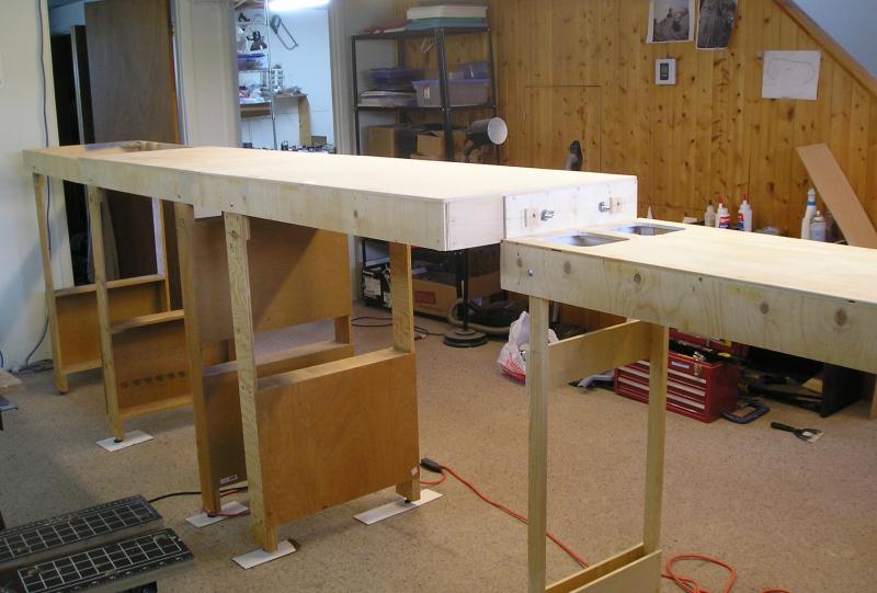
…and from the other end of the room.
I'm impressed with the size of the thing, the three main layout boards total 11'.
I made pads from hardboard for the feet - otherwise the legs sink into the carpet.
Full height boards are 4'. I have no wish to strain my back bending over low boards. This is a very comfortable height.
John
John
Posted
Full Member
I really like that dropped module. Got me thinking about a long, curved trestle on that 5+3-foot module. Which should give some members pause (and ensure slow speed running) as some of their trains come in at around $1000.
I shall take photos at the next gathering in August.
Nigel
©Nigel C. Phillips
Posted

Inactive Member
I enjoy this part of the build as much as any other.
Max
Port Elderley
Port Elderley
Posted
Full Member
A trestle always looks cool Nigel.
I'll stock up on foam core board tomorrow and start sketching in the details, to see what works.
John
John
Posted

Full Member
I like the height and the screw less build. I take it that the legs are to be detached during transport and due to their length they don't fold up underneath the boards?
Marty
Posted
Full Member
John
John
Posted
Full Member
One requirement that I think is important for an exhibition layout is that the legs be universal as much as possible. To that end, if I find bolts (1/4" carriage) that are so stiff as to require a hammer to get them out, I run the drill through them to open the holes.
A similar requirement is for the baseboard end bolts (3/8" carriage) to be loose (remember the dowels do the alignment). I found that pretty much all the bolts are very tight and require persuading to go in and come out. So again, I ran the drill through the holes to open them. With carriage bolts, there is a square land that should be pressed into the wood. I did this also using an adjustable wrench.
The main job has been to install cross braces which is pretty much done for the small boards. I'll hold off with the main boards until I know where points are going.
Last job was to make a card template for the outside radius of the angled boards. I will glue foam to the outside of these to get a nice rounded look to them.
I made the template using a trammel:
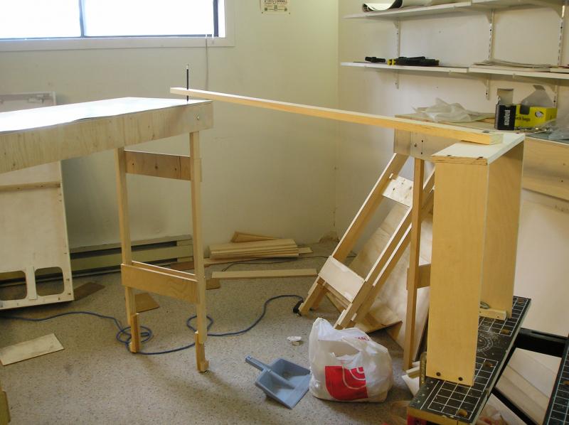
No rocket science here. Astonishing how things turn into a tip so quickly.
John
John
1 guest and 0 members have just viewed this.