Terminus Layout Station Plan
Posted

Full Member
Hi Ian.I have just found this thread and what a wonderful layout you have there.
I too am in the final stages of building my own room within our garage space.
I love the idea for the baseboard supports and this has made me rethink my proposed design and will be working on this idea over the coming weeks.
I would just like to echo everyone else's comments;
"Stunning", "Elegant", "Inspiring", etc
Well done and looking forward to more posts.
ATB,
Ian :mrgreen:
I'm glad you like some of my ideas.
I've been building this layout for some years now so it has taken time. Having said that I only work on it a few hours weekly.
Its a hobby after all. If you push too hard there's a chance you could lose the enthusiasm & tire of it. I think my layout is about the maximum size for one person especially for someone working alone.
When I was building my layout room I decided one of the most important things was insulation. You can never have enough of it.
The walls of my room are lined with 2" Kingspan type insulation which has a plasterboard finish. When fitted you just tape the joints & skim over them with a filler made especially for covering joints. I also use a small dehumidifier on a low setting. When the moisture content of the air reaches a certain level the dehumidifier removes the excess moisture.
No matter what time of the year is it or no matter what the outside temperature I can feel comfortable in the room with a shirt.
Moisture is the thing which is most damaging to a model railway.
Cheers.
Tony.
"The only stupid question is the one you don't ask"
Regards.
Tony.
Regards.
Tony.

Posted
Full Member
Well the search for a plan goes on.
I have narrowed it down to about three which I am looking at seriously.
What hasn't helped is that I met someone yesterday who because of a house move is downsizing.
He presented me with about five years worth of what seems like every model railway magazine produced during that time.
I will now have to go through them all to see if there are any suitable plans hiding in there ;-)
I'll keep working at it.
I have also been reliably informed that my birthday is next week.
As you get older you tend to conveniently forget these events

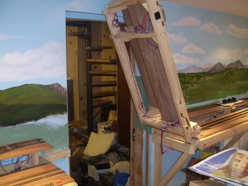
In the meantime here are some photos of the remaining part of my layout that I promised in my last posting.
In my last photo posting we had reached the right hand end of the layout where you can see the hidden sidings on the bottom.
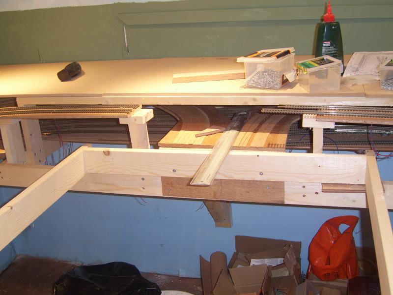
We now return back around to the entrance door wall.
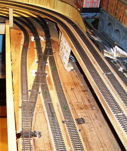
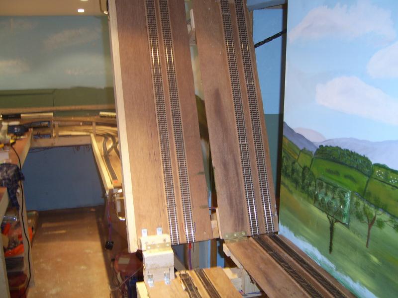
In this photo you can see the tracks from the hidden siding coming from the left with the right hand tracks from the terminus coming from under the bridge on the right. The two tracks in the center are the tracks that go across the entrance to the terminus.
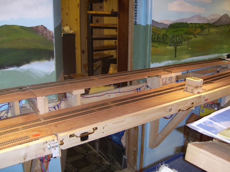
In this photo you can see the entrance door & the lift up flap in the lowered position. The previous photo is on the left of this photo.
I these last twp photo's we see the lifting door flap in various positions.
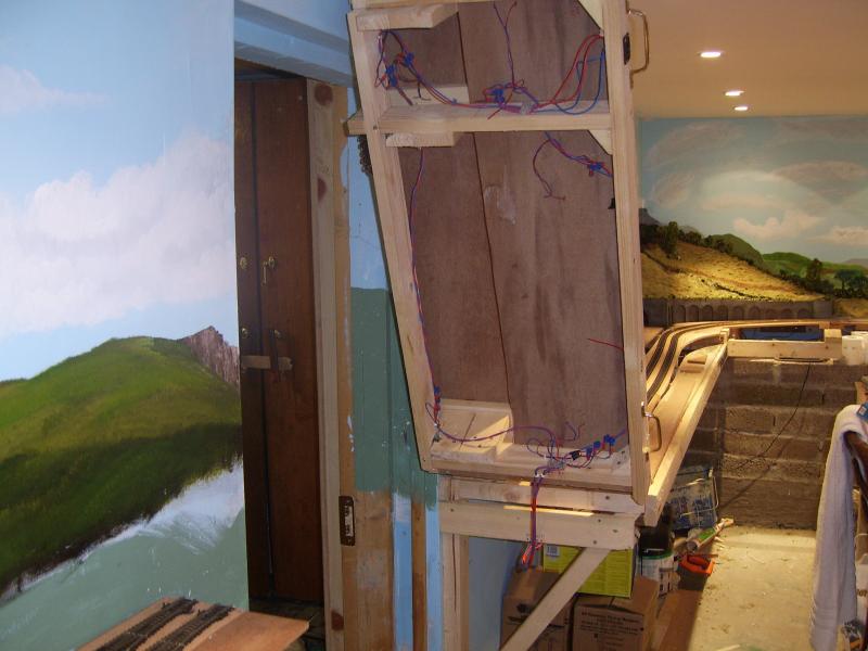
That concludes the early photos of the layout.
I will get back with some more soon.
Meanwhile I will continue with my quest for a terminus plan.
Daughter & grand children are here now for the weekend so family matters are calling.
Cheers.
Tony.
"The only stupid question is the one you don't ask"
Regards.
Tony.
Regards.
Tony.
Posted
Full Member
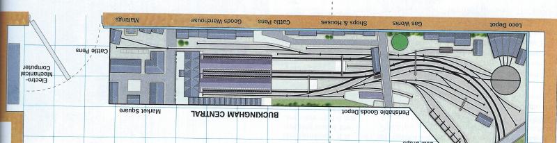
While in Costa coffee the other day I spotted a Model Railway Encyclopedia produced back in 1979 among some books provided for customers to browse through.
In this book I spotted a terminus plan. It was Buckingham Central from Peter Denny's Buckingham Branch lines fame.
Don't know why I hadn't spotted this plan earlier as I have his books among my collection.
This is the plan in question.
Over the weekend I worked on this plan with the SCARM software which is free to download & use without restriction for personal use.
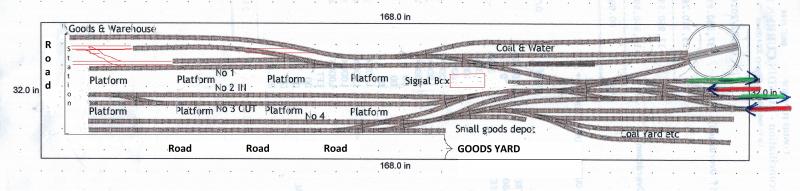
After some time I came up with this which has everything I was looking for in a terminus plan.
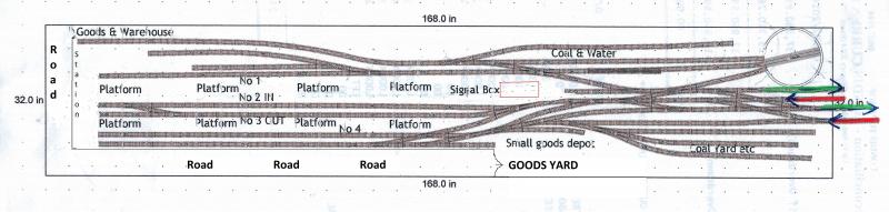
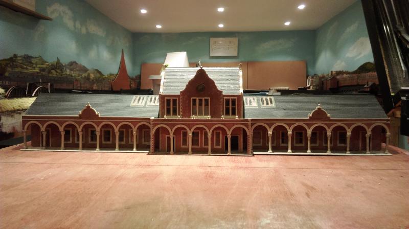
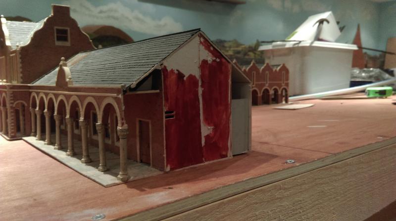
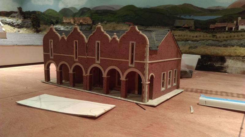
I had intended to use the station photo's of which I put in an earlier posting but despite my best efforts I can't seem to find a way to fit it in the plan unless I cut it down & make alterations to it. I'm a bit slow to do this as I don't want to ruin a very nice model.
See what you think of my plan.
Ideas, suggestions or advice are most welcome.
Regards.
Tony.
"The only stupid question is the one you don't ask"
Regards.
Tony.
Regards.
Tony.
Posted

Full Member
Just caught up with the thread. Fantastic progress, wish I had the space.
As far as I can see Mr. Freezer's plans and prototype track layouts were sometimes a bit removed from each other. These plans were done in the "cram it in" days (two inglenooks side-by-side!) when it was obligatory to have everything, no matter what space was available. There are some examples of prototypes that actually come close because of space constraints. One example of a "cram-it-in" terminus is below.
Rewley Road terminus station in Oxford (LMS) had a 6-road inglenook goods siding, carriage sidings, a passenger station with two platforms, a goods shed, goods platform, a two-road engine shed and turntable, and some interchange sidings with the GWR (second inglenook). Plus a swing bridge over the river Isis separating the engine shed/turntable from the station. There was also a private siding for the GRC&W Co. repair facility at one time. And all in very little space. I thinks a track plan based Rewley road in 1952 would fit nicely in the space that you have. PM me if you don't have a plan.
Nigel
©Nigel C. Phillips
Posted
Full Member
In the meantime I would be interested in what others think of the last terminus plan I posted ?
Cheers.
Tony.
"The only stupid question is the one you don't ask"
Regards.
Tony.
Regards.
Tony.
Posted

Full Member
That looks an interesting plan and I do have some comments but before doing so I need a better understanding of how the terminus will operate
Is it possible to repost the plan with some notes regarding the purpose of the various sidings…..for example I am not clear which is the track served by the coal and water
Similarly P2 is described as in and P3 as out. Is the intention for the principal trains to arrive at P2 and depart from P3 after a loco change? Which is the headshunt for the carriages during this manouvere?
An indication of train lengths would be helpful…..ie P1 2 car push pull/DMU……….P2. 4 coach with tender loco…………I don't need a detailed timetable just an idea of how you contemplate operating
Shame about the station….super model…..what are the dimensions?
It's 9 am here and I have to go out for a few hours ……so there is no rush to reply
Regards
John
Posted
Full Member
The best way to answer your question is to put in answers as you posed the questions. I will answer them as honestly as I can.
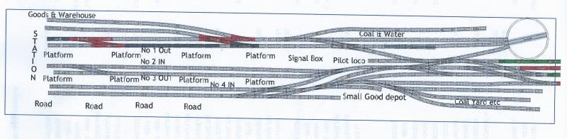
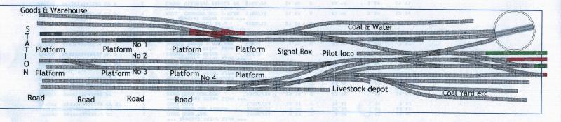
In the image below I have added a few new connections in RED. I thought I might use the 2nd track down (top left) as a goods reception road for that part of the layout ?
Regards.
Tony.
[/user]
[user=434]John Dew[/user] wrote:
Hi Tony
That looks an interesting plan and I do have some comments but before doing so I need a better understanding of how the terminus will operate.
Is it possible to repost the plan with some notes regarding the purpose of the various sidings…..for example I am not clear which is the track served by the coal and water.
The track served by coal & water is the 2nd one down (under the words)The top track could be used for loco coal storage etc
The 3rd track down could be used for ask pits / inspection pits ?
Similarly P2 is described as in and P3 as out. Is the intention for the principal trains to arrive at P2 and depart from P3 after a loco change? Which is the headshunt for the carriages during this manouvere?
Yes these would be the principle platforms. I didn't think I would need a head shunt as the in platform track has a release for the loco to escape for service etc. The station pilot stored in a spur in front of the signal caboin could pull the carriages out along the top in mainline while the main loco was being serviced & push them back into the main out platform to await the return of the mainline loco.
An indication of train lengths would be helpful…..ie P1 2 car push pull/DMU……….P2. 4 coach with tender loco…………I don't need a detailed timetable just an idea of how you contemplate operating.
Platform 1 & 4 are 60" in length approx while the main platform roads 2 & 3 are 80" approx in length.
Shame about the station….super model…..what are the dimensions?
The station dimensions are 37.5" long & 6'5" at its widest in the center. If I remove the end towers it would become 28" & my baseboard is 32" in width. I put in a photo of the station below. It came from some kind of exhibit I would think as it has no end on the left hand side & the platform side is just blank card. I'm sure I can fix that if needed.

It's 9 am here and I have to go out for a few hours ……so there is no rush to reply
Regards
John
"The only stupid question is the one you don't ask"
Regards.
Tony.
Regards.
Tony.
Posted
Full Member
That is, indeed, good news about the station……..its such a splendid model it will look perfect at the end of the peninsular. It shouldnt be too difficult to make up a side and platform side wall using Scalescene Papers. The large station kit has a lot of papers that can be adapted……you can see most of them on either the Granby thread or the one I posted covering the building of the station wing.
An alternative to removing the end towers would be to extend the width just at at the very end of the peninsular…..you only need 3" either side
creating a sort of TRather than having an overlong post I will send a separate reply about the platform layout
Cheers
John
Posted
Full Member
I started Granby with in and out platforms for my suburban service but came to the conclusion it was better for the train to arrive and depart from the same platform……its far more efficient from an operating point of view and I suspect more prototypical. I eliminated release xovers. In the rush hour the new loco couples up and pulls out on the next trip thus releasing the incoming loco for servicing. Outside of the rush hour the station pilot pulls the carriages out into a head shunt releasing the incoming loco. Head Shunt/Carriage siding are very desirable but not essential……..the pilot pulling the coaches temporarily on to the main running line to release the loco will work……..which makes your release xover redundant
………and it means P3 is available for another train.The system I described above uses Pannier (naturally
) tanks but would work equally well with tender engines that need to be turned at the end of the shift.Your servicing and TT area is quite typical for a busy medium sized terminus with a lot of passenger traffic……its a little different from a shed though……….Locos need somewhere to dump ash but not in the same quantities as a shed……..once they had taken on coal and water and tender locos had been turned they would go to a stabling siding ready for their next shift…….ideally with an inspection pit so the driver could do some oiling. It would be very unusual in a terminii such as yours for tank engines to be turned so you may want to map out the most efficient way of coaling and watering without tank engines blocking the entrance to the TT
Another long winded reply I am afraid………I get the sense that passenger traffic is the principle focus of the terminus……if this is so then best to get that all sorted before considering goods movements
Hope this helps……if not ignore it
Cheers
Posted
Full Member
Hi John.Hi Tony
That is, indeed, good news about the station……..its such a splendid model it will look perfect at the end of the peninsular. It shouldnt be too difficult to make up a side and platform side wall using Scalescene Papers. The large station kit has a lot of papers that can be adapted……you can see most of them on either the Granby thread or the one I posted covering the building of the station wing.
An alternative to removing the end towers would be to extend the width just at at the very end of the peninsular…..you only need 3" either side
Rather than having an overlong post I will send a separate reply about the platform layout
Cheers
John
I was half afraid to start slicing up the Station building for fear of making a mess of it. I don't know why as I know I can do it.
What I was wondering about was how to cut through the building.
Should I use a scalpel with light strokes & do it slowly or should I use my Dremel & a thin cutting disk ?
I can't widen the baseboard because the clearance between baseboards is already down to the minimum. I'm having to learn to skip sideways as I get older :)
I already read through your Grandby thread but will be doing so again.
Regards.
Tony.
"The only stupid question is the one you don't ask"
Regards.
Tony.
Regards.
Tony.
Posted
Full Member
Now down to the serious business.The platform faces are a good length……..you should be easily able to accommodate 6 car trains with a decent sized engine.
I started Granby with in and out platforms for my suburban service but came to the conclusion it was better for the train to arrive and depart from the same platform……its far more efficient from an operating point of view and I suspect more prototypical. I eliminated release xovers. In the rush hour the new loco couples up and pulls out on the next trip thus releasing the incoming loco for servicing. Outside of the rush hour the station pilot pulls the carriages out into a head shunt releasing the incoming loco. Head Shunt/Carriage siding are very desirable but not essential……..the pilot pulling the coaches temporarily on to the main running line to release the loco will work……..which makes your release xover redundant
The system I described above uses Pannier (naturally
Your servicing and TT area is quite typical for a busy medium sized terminus with a lot of passenger traffic……its a little different from a shed though……….Locos need somewhere to dump ash but not in the same quantities as a shed……..once they had taken on coal and water and tender locos had been turned they would go to a stabling siding ready for their next shift…….ideally with an inspection pit so the driver could do some oiling. It would be very unusual in a terminii such as yours for tank engines to be turned so you may want to map out the most efficient way of coaling and watering without tank engines blocking the entrance to the TT
Another long winded reply I am afraid………I get the sense that passenger traffic is the principle focus of the terminus……if this is so then best to get that all sorted before considering goods movements
Hope this helps……if not ignore it
Cheers

I don't really have a lot of prototype knowledge not having lived in the UK so I turned to logic for my design.
I tried as far as possible to make sure that any movement within the station area would not conflict with any other as far as possible. In other words trains should be able to come & go at the same time without any conflict.
It should also be possible to shunt wagons in the various siding for the various industries without affecting main line running in any way.
I think my design does that as far as I can see but I stand to be corrected by those with more knowledge than I ?
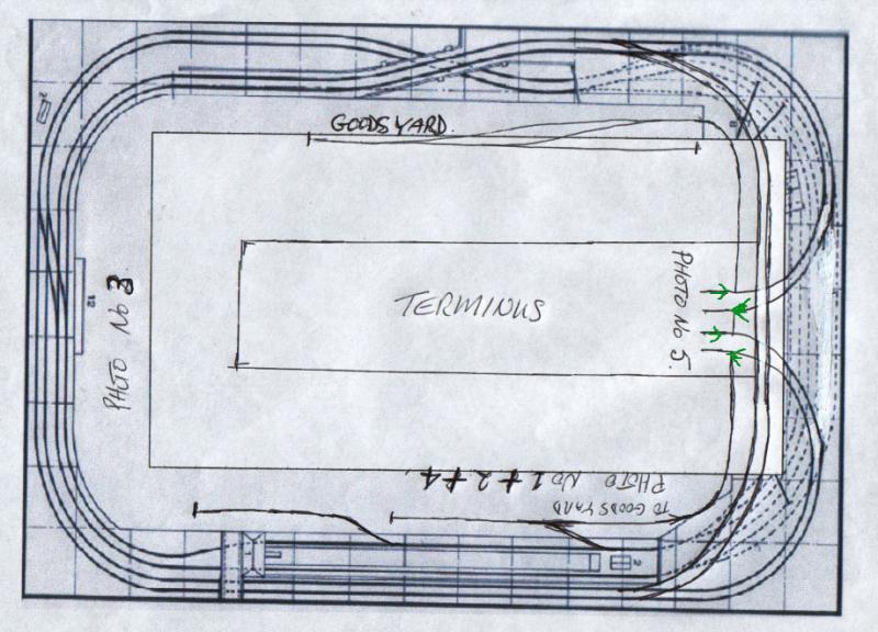
This is the plan of my present layout with space for the terminus down the center peninsula. I did make some changes along the bottom of the plan with the edition of a crossover & changes to the sidings but theyre not shown here.
I have made a few point changes (Red) to my plan which you can see below. The changes I made were to create a goods reception road. Don't know whether this is prototypical or not but it seems logical to me. Without this release any loco bringing in a goods train is trapped until released by another loco.
This however does affect the use of Platform No1 ? Any ideas on this ?
The only place I can see for a loco stabling road is the middle road off the turntable which can be reached from the turntable as well as the main. This wouldn't affect turntable use.
What I want to run is a mixture of passenger & goods whenever the fancy takes me. What I don't want is for it to look silly.
Cheers.
Tony.
"The only stupid question is the one you don't ask"
Regards.
Tony.
Regards.
Tony.
Posted
Full Member
[user=434]John Dew[/user] wrote:Hi Tony
Hi John.
I was half afraid to start slicing up the Station building for fear of making a mess of it. I don't know why as I know I can do it.
What I was wondering about was how to cut through the building.
Should I use a scalpel with light strokes & do it slowly or should I use my Dremel & a thin cutting disk ?
Hi Tony
Assuming the construction is card….Scalescene style……then I would go with a scalpel down the corner joint.
The cut can be concealed with L shaped pillars……the roof tiling will be trickier but again concealable .
Good luck!
Posted
Full Member
Personally I wouldnt bother with the Xover. It significantly reduces the size of any goods* train that you could shunt. I would use the siding above "Coal and Water" as a head shunt…….the station pilot could draw the train back into this siding thus releasing the incoming loco and then shunt the goods train into the two sidings…….far more efficient and far more prototypical.
I have made a few point changes (Red) to my plan which you can see below. The changes I made were to create a goods reception road. Don't know whether this is prototypical or not but it seems logical to me. Without this release any loco bringing in a goods train is trapped until released by another loco.
This however does affect the use of Platform No1 ? Any ideas on this ?
It is not essential to store Loco Coal or Ash wagons in this top siding……..its a service/turning area rather than a full on Engine Shed complex
* As you already have a goods depot…bottom right……. you may want consider calling the "Goods & Warehouse" a parcels depot. It would be unusual to have two goods depots in the same station (unless it was a joint line) whereas it was normal practice to separate parcels traffic from goods traffic. Parcels were carried on passenger rated vans either in dedicated trains or as tail traffic on passenger trains…….lots of operating potential for you there.:thumbs
I see you are still committed to the separate In Out platforms concept


Cheers
Posted
Full Member
[user=710]amdaley[/user] wrote:
Hi John.[user=434]John Dew[/user] wrote:Hi Tony
Hi John.
I was half afraid to start slicing up the Station building for fear of making a mess of it. I don't know why as I know I can do it.
What I was wondering about was how to cut through the building.
Should I use a scalpel with light strokes & do it slowly or should I use my Dremel & a thin cutting disk ?
Hi Tony
Assuming the construction is card….Scalescene style……then I would go with a scalpel down the corner joint.
The cut can be concealed with L shaped pillars……the roof tiling will be trickier but again concealable .
Good luck!
Last night we had a late surgery.
The patient has had a successful amputation & the prognosis is good for a full recovery ;-)
Here's a photo of the orphans
Cheers.
Tony.
 Last edit: by amdaley
"The only stupid question is the one you don't ask"
Regards.
Tony.
Regards.
Tony.
Posted
Full Member
[user=710]amdaley[/user] wrote:Personally I wouldnt bother with the Xover. It significantly reduces the size of any goods* train that you could shunt. I would use the siding above "Coal and Water" as a head shunt…….the station pilot could draw the train back into this siding thus releasing the incoming loco and then shunt the goods train into the two sidings…….far more efficient and far more prototypical.
I have made a few point changes (Red) to my plan which you can see below. The changes I made were to create a goods reception road. Don't know whether this is prototypical or not but it seems logical to me. Without this release any loco bringing in a goods train is trapped until released by another loco.
This however does affect the use of Platform No1 ? Any ideas on this ?
Xover has been eliminated.
Resistance was futile :twisted:
It is not essential to store Loco Coal or Ash wagons in this top siding……..its a service/turning area rather than a full on Engine Shed complex
* As you already have a goods depot…bottom right……. you may want consider calling the "Goods & Warehouse" a parcels depot. It would be unusual to have two goods depots in the same station (unless it was a joint line) whereas it was normal practice to separate parcels traffic from goods traffic. Parcels were carried on passenger rated vans either in dedicated trains or as tail traffic on passenger trains…….lots of operating potential for you there.:thumbs
We now have a livestock area bottom right ?
I see you are still committed to the separate In Out platforms concept
Engineers these days :roll:
So demanding
No more in or out.
I think maybe we're getting there.
Any other ideas ?
Cheers.
Tony.

"The only stupid question is the one you don't ask"
Regards.
Tony.
Regards.
Tony.
Posted

Full Member
I've let John do the talking 'cause he's got the experience with big terminals, but I've agreed with all he's said and I can't see anything else I'd change on that layout.
Maybe, just maybe, I'd see if there was enough space to put a little cantilever board around that turntable and have a small two or three stall roundhouse, but that'd be it.
Parcels traffic either goes loco first into the goods and warehouse to be emptied immediately or into platform one where the pilot takes care of the vans and releases the loco.
Those two roads onto and off the turntable get a bit close and you may have trouble with the clearing point (two locos passing or side by side) but you can refine the approach when you lay the track.
Just my thoughts.
Marty
Posted
Full Member
Hi Marty.Tony,
I've let John do the talking 'cause he's got the experience with big terminals, but I've agreed with all he's said and I can't see anything else I'd change on that layout.
Maybe, just maybe, I'd see if there was enough space to put a little cantilever board around that turntable and have a small two or three stall roundhouse, but that'd be it.
Parcels traffic either goes loco first into the goods and warehouse to be emptied immediately or into platform one where the pilot takes care of the vans and releases the loco.
Those two roads onto and off the turntable get a bit close and you may have trouble with the clearing point (two locos passing or side by side) but you can refine the approach when you lay the track.
Just my thoughts.
Marty
Glad you like the plan.
I had spotted that possible problem with the turntable lead on roads but that area will need cleaning up as I build the plan.
I was stuck with the turntable provided by the software.
I had also hoped to have a loco shed of some kind but I'm pretty caught for space in that area.
Hopefully I will have space for some loco spurs or a small shed but I might have to be satisfied with a low relief structure.
We're talking a matter of inches so I'll have to wait & see.
Regards.
Tony.
"The only stupid question is the one you don't ask"
Regards.
Tony.
Regards.
Tony.
Posted
Full Member
There is something odd with YMR today……I am having serious connection problems but only this site:shock:
Anyway I have briefly achieved success with the iPad
Super job with the surgery on the station:thumbs to quote Morecambe and Wise you won't be able to see the join.
I do believe the layout modifications you have made will make operating far more efficient and pleasurable.
I agree with Marty about the TT roads. You could actually get by with just an entry road and an exit. The current topmost road could be a conventional stabling siding for tank engines……..coal and water facilities would be shared with the TT Entry road for tender locos.
Short stubs off the TT will be great for stabling tender locos and very prototypical for a termini such as yours…….it would be unusual to have a shed so close to a city centre termini in real life. Please don't quote Granby at me:oops::oops: I am busy trying to create the illusion station and shed are separated by quite a distance:roll:
Some questions I should have asked ages ago ……I don't see the answers in prior posts
1 Code 100 or 75. ?
2 DC or DCC
3 How will the turnouts be operated?
Kind Regards
John
Posted

Inactive Member
Best regards
Tech Support. ;-)
Max
Port Elderley
Port Elderley
Posted
Full Member
Congratulations on the well earned promotion
Acting and unpaid I assume?
1 guest and 0 members have just viewed this.