NotMutley - take 2
Posted

Full Member
Freelance 00 layout
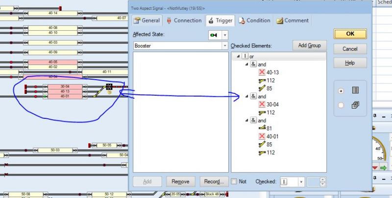
This is the signal I am experimenting with. The logic for driving the green signal is listed - the default is red.So the question now is how do I get a loco function into the equation I was thinking maybe a flagman may help but it doesnt reference specific locos
 Last edit: by gdaysydney

Posted

Full Member
Max may be able to help I think he created an EA to handle lighting etc in his warehouse
Cheers
John
Posted

Inactive Member
The lights in the engine shed were part of a Start List in Schedules for one of the locos. I remember doing an EA for something, but I can't remember what it was for. :oops:
I remember documenting it at the time, so I'll have to go looking for it.
We are on a trajectory towards going to market with our house in August (and Wendy bought me an RC model aircraft for my 70th), so my train modelling is on the back burner at the minute.

I'll report back as soon as I find something.
Cheers
Max
Port Elderley
Port Elderley
Posted
Inactive Member
Here is the link to the Extended Accessories page.
http://www.modelrailcommand.com/view_topic.php?id=1064&forum_id=21
Cheers
Max
Port Elderley
Port Elderley
Posted
Full Member
As usual the TC manuals are very light on and I find them as good as useless. I'll have a go at the step by step process Max has documented and report back. I am sure it is possible - I suspect its like the Apollos first trip to the moon - lots of course changes on the way to the target
Posted
Full Member
I thought Max's step by step was great and I kind of got the hang of how it could work with a dummy loco………look forward to seeing how you get on
Cheers
John
Posted
Full Member
Success !!
It took a bit of trial and error but it wasn't as difficult as I thought it might be. Max's step by step guide was very helpful. :thumbs
It needed two functions per switch for a two aspect signal and it didn't work first up until I remembered from the KD shuffle days that TC doesn't like two commands at the same time so I had to put in a delay. ( A three aspect signal would need three functions per switch)
I will put together a word document explaining exactly what to do so that anyone using TC with the Light It decoder for signalling will be able to follow it
Thanks again gentlemen - There was a touch of deja vue having the three of us plus Wogga (Pete) working on a solution.
Talking of Pete has anyone heard from him- it must be 3 years since he said he was going to pull stumps on his layout?
Last edit: by gdaysydney
Posted
Inactive Member
I'm getting further and further behind as I try to wrangle my RC aircraft. :???:
I'm still only about 1/3rd the way into my pilot training. :roll:
I always was a slow learner - even slower, now I'm in my 70's.
I think Pete has moved on. His stuff is still on YouTube, though.
Max
Port Elderley
Port Elderley
Posted
Full Member
Whilst installing signals on my layout I have discovered that in the original document the function settings for the Light It are back to front ( compensated by a wiring error) as my UK manufactured signals use a negative rather than NCE's positive common.
Document has been updated to avoid confusion
Last edit: by gdaysydney
Posted
Full Member
Thats an excellent summary Dave……..I have filed it away for the future….I am sure I will eventually need to insert an EA into Granby
Cheers
John
Posted
Full Member
Thanks John, the credit should go to Max - I just piggy backed off his tutorial .I have downloaded it though it doesnt show:hmm
Thats an excellent summary Dave……..I have filed it away for the future….I am sure I will eventually need to insert an EA into Granby
Cheers
John
Posted
Full Member
At the moment I have four home signals and have ordered 4 more but I guess I should also install some away signals as well. - I expect to need about ten - twelve signals in total
I am not an expert on British signalling - or on any other for that matter - Green for go red for stop is about as far as I have got. So my questions to the club members -
- Is there a simple guide for the placement of signals that I can refer to? Which side of the track, how far away from points etc
- How does the away signal interact with the home signal ? Am I correct in assuming that in a given direction of travel the train will encounter an away signal first. If this is correct I'm thinking that I might only need two away signals on my layout.
- I am not modelling a particular era but it is loosely based on the 1960-1980s when I was growing up ( reliving my childhood ? :roll:) The signals I have are two aspect - is this correct for this era or should I be also using three aspect signals and if this is the case where would they be located?. I plan to have a few operational semaphore signals as well just for interest sake. Thank goodness for preserved lines !!
Posted
Full Member
I imagine that there will be replies from members far more knowledgeable than I , particularly regarding lights as opposed to semaphores.
Signals were placed on the near ( ie LH ) side but if visibilty was an issue this was sometimes varied.
Regarding placement…..there is probably a very precise ruling somewhere……I take the common sense approach that the signal is placed sufficiently far in front of the junction to ensure no risk of contact with a train on the other line
My bible is C J Freezers "Signalling"…….if you havent got a copy I would strongly recomend trying to get one
I have only skimmed the light section but my understanding is that when lights were first generally installed they replicated semaphore practice. The line was divided into blocks (just like TC) eack block controlled by a signal box. A home signal controlled entry to the block and a starter ( your away?) controlled exit from the block……….the distant signal indicated the status of the next block……..off all was well….on proceed but with caution
This is very very simplistic…..there were inner and outer home and starters or shunt ahead arms to control movements within station limits……., and naturally the GWR had some unique signals of their own which continued with BR Western region.
If you could post a sketch of your track plan with the proposed signals I ( and others ) may be able to provide more specific help
I am very envious…….one of my major regrets is that Granby's signals are only cosmetic
Posted
Full Member
Whats the convention for the default state of a signal. I have assumed that a signal will turn to red until a train approaches.
( In TC ths is achieved by making a condition that the current block is either occupied or reserved)
Posted
Full Member
Posted
Full Member
The decoders can be piggy backed with the track power or a separate 12 v supply. For the moment I am going with track power.
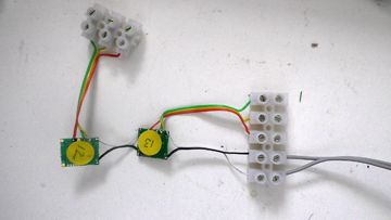
Typical me, the first physical installation is a double signal. After determining which wires belong to which signal I have used a piece of heat shrink tube to hold the wires of one signal (13) together for installation.
Since the decoder and the signals operate on different "common" ( decoder positive - signal negative) I have also marked with red nail varnish the white wires that are now the red signals.
This should make life easier when I get under the layout and guarantee that its correctly wired at the first attempt.

Posted
Full Member
After a lot of checking and discovering the problem I reverted to soldering!! :roll:
Last edit: by gdaysydney
Posted
Full Member
As I have not included a layout schematic for some time I thought it might help those following my posts to see one of this version of Notmutley.
The layout consists of a fiddle yard on the North side (top) and a station area on the south side. There is also a station by-pass which runs behind the station area under buildings.
The track in the NW corner ( top left) is removable to allow access to the train room and the available space dictated that there was only room for 3 tracks which has limited the options for trains going clockwise around the layout. Trains traveling anti clockwise have numerous operational options.

The schematic is the switchboard screenshot from RR&Co and I have indicated two of the recently added Extended Accessory icons. These are only visible in edit mode. In run mode they disappear so that only the signals show.
For those wondering what the arrows are at the top of the page these are route indicators. When running the layout manually I can click on these to switch all points required for a designated route. It saves a lot of time and derailments. Eventually I will also have virtual signals in the fiddle yard to indicate which routes are clear and which are not.
Posted
Full Member
Your switchboard is a lot neater than mine
Mine got so complicated that I split it into 4 sections :roll: This has advantages and disadvantages………I am still sorting out the aftermath of some of the disadvantages :shock:
Thats a really cool idea to set up route buttons……I hadnt thought of that….thank you. I am constantly shuffling stuff in and out of the storage yard manually…….and I invariably forget one turnout :oops:. Your idea will solve that
Regards
John
Posted

Full Member
I must say that I am mightily impressed by this knowledge of technology, programming, and all - I thought it was all smoke, mirrors and hamster wheels.
This is certainly one area of railway modelling that (at my age) I will steer clear of and simply use DC control and old school control equipment. My layout sounds like it is very much the poorer for not having your computer control, but at least I understand it when it doesn't work - its normally something I've pushed when I shouldn't have!!!
Dave - can you outline the raison d'etre for it all - interlocking, automatic control?? It might help us ludites put it all into perspective/realise what we are missing.
Barry
Shed dweller, Softie Southerner and Meglomaniac
1 guest and 0 members have just viewed this.