Japanese N gauge
Posted
#198301
(In Topic #11008)
Inactive Member
It may never happen, but I hope it does.
Several years ago I found a reference to Modratec lever frames. Since then I have had it in mind to build one, but needed an excuse to justify the expense.Seeing Gormo's beautiful lever frame in its little wooden setting finally tipped the balance in favour of getting a Modratec frame.
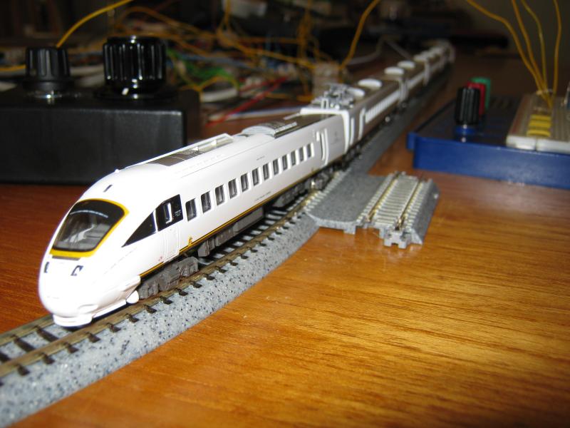
I have some Kato N gauge Japanese EMUs that haven't run for a few years, so I am trying to put together a layout to combine the two.
Before I commit to it I want to get the design worked out in detail, there is always the chance of hitting some unforeseen snag that will kill the project. I have tried several schemes: Terminus + fiddle yard, Through station with two fiddle yards etc. and the one I am left with is this:

The Modratec frame will be part of a working signalbox covering the station area. The fiddle yard represents the adjacent signal boxes up and down the line from the station and will be operated with TrainController Gold. TCG will also drive the trains according to the signals. My role will be signalman, not driver. I have chosen to omit all goods facilities, partly because I am not up to making reliable uncouplers in N gauge but mostly because I want a frequent passenger service in a suburban station without extra complications.
The plan is 15ft x 3ft. I thought about building it as three boards of 5x3, but on balance I think it would be safer to go for six of 5ft x 18ins. 15 x 3 is about as big as I want to go for a portable layout sited in the garage. If I could get it smaller I would, but not at the expense of operational difficulties.
It will assemble in my garage and can be left there for lengthy periods, but there will be times when it has to be taken down. The plan then is to store it on shelving across the back of the garage. Also I hope that I will be able to exhibit it, but I know nothing about the sort of layout that is welcome at exhibitions, especially in terms of operational complexity and preferred sizes.
At this stage this plan is the best I can come up with, but I am not committed to it. I will welcome any comments and suggestions for mods or drastic changes, also information about the practicalities of an exhibition layout.
Regards,
Brian
ECoS, Laptop, TrainController Gold v8
Brian
ECoS, Laptop, TrainController Gold v8

Posted
Guest user
Where would you intend to operate this from if exhibiting ? It may be an idea to give yourself enough depth for an operating well in the centre. Only have the front platform scene on general view and the fiddle yard out of sight.
Looks like a good length for some long trains. I'm sure that there will be plenty advice on the UK exhibition circuit that can help you out.
Good luck meanwhile and keep developments coming. Looks very interesting.
Cheers
Toto
Posted
Full Member
If planning to exhibit also consider transport.
Although not planning to exhibit "Gresleys Run" we did think about what would happen in a house move scenario. In this case each module is built to fit within the available transport. In our case the 6' load bed of the work van that I can borrow.
Can your car, van, truck, bicycle or local bus company carry 5' modules.
Andrew
Posted
Full Member
Have you got Kato track as well?
There is a system called T trak (http://www.t-trak.org/) that I have seen examples of here which might lend themselves to the type of layout you want to build as an exhibition layout. I note your plan has nice flowing curves so T trak can look a bit "trainsetesque".
The beauty of the modules ala Freemo is you could get up and running quickly and expand it rapidly two small modules at a time. Your station and fiddle yard at the back could be placed at an offset if you did the lot in one go…
Just a suggestion,
Regards from Oz
Trevor
 Last edit: by xdford
Posted
Inactive Member
Talk about baseboard sizes has made me realise that I could not possibly pick worse places for the baseboard joins. The fiddle yard and station will be laid in flexitrack, and as it stands I will have to solder 44 rail ends to 44 screws to cross the joins.
It would make more sense to put one vertical join down the centre line: 22 soldered ends, and further joins 2' 6" from each end of the layout: 16 soldered ends. This would give four boards of 5'x18" and two of 3'x2'6". The last two placed side by side would have the same footprint as the other pairs, all 5x3. This would have a further advantage that the semi-circular ends would not need joints. These will be Kato superelevated double track, 381+414mm.
If it ever gets to an exhibition I would have to rent a small van. The ones currently on offer claim to have load areas well in excess of 5x3, but it costs very little more to rent the next size up.
I looked up the t-track reference, but I think it would be difficult to use it in my situation. One thing that struck me was its reliance on the Kato joiners to carry traction current when advice from almost every other source says that is asking for trouble. I plan on a minimum radius of 381mm for the unitrack curves, and I did not see that in the t-track specs. I do need the angled approaches to the station to avoid reverse curves through the points and the t-track spec. seems to prohibit that sort of non-conformity.
I have loads of Kato track, but the spacing of the large radius points is inconvenient and I find the small radius points give occasional derailments with one or two Kato trains. I am tempted to use it in the fiddle yard straight sections, but it is probably best to avoid peco/kato transitions if I can, so it's only the curve ends that will change makes.
I did consider a large oval with a central operating area, but I am getting too old to crawl on hands and knees under the baseboards, and a robust and accurate lifting section would be extremely difficult to build with portable boards. The other disadvantage is that there would be conflicting pressures on the design. Portability and light weight require a large oval to have narrow boards. I have this problem on my 00 layout where there is little room for scenery. This board is 12" wide:

The 15x3 can sit in the middle of the garage with easy access all round and has useful areas for the property developers to work on, especially if I put removable lids over the fiddle yard.
Toto, your question about operating at an exhibition got me thinking. I can only guess, but a layout 15' wide must merit a depth allocation of at least 8'? This would allow me to put the front of the layout between 2 and 3ft behind the crowd line. The lever frame and its block shelf will be free standing and could go at the front of the layout, off to one side of the station and angled at around 45deg. so that I could sit at right angles to the layout to chat to any spectators who failed to walk fast enough. The laptop and Ecos could go around the back either up against or below the fiddle yard. Is this realistic?
Last edit: by Brian R
Regards,
Brian
ECoS, Laptop, TrainController Gold v8
Brian
ECoS, Laptop, TrainController Gold v8
Posted
Inactive Member
This means that every track in the yard needs access to both main lines at both ends. I cannot see a way to avoid
1 Bottlenecks at both ends
2 Sixteen points taking up about six feet of baseboard length (and a large chunk of my wallet)
3 No possibility of a long run to allow block working.
I am back at the drawing board with a totally different main line. It still needs work to get it in shape, and it may not be practical.
After following up Trevor's (xdford) reference to t-trak.org and looking at videos of it on YouTube I think I may go for Unitrack for the whole layout. I have plenty of it. I don't need modules to connect up to other people's work so I need not go for t-trak sizes, but relying on UniJoiners to carry traction current means I don't need to worry about matching rail joints to baseboard joins. Frequent making and breaking of joints should keep them conducting reliably. It probably means an end to hopes of exhibiting though. It certainly means an end to sweeping curves and a smooth run through the station. It also makes it easier to eliminate the fiddle yard in favour of a long and curvy main line run.
When I make progress with the revised main line I will post a new plan, but meanwhile I think the station layout is looking workable, I have no plans at present to change it and I am looking at the signalling scheme.
This is the SigScribe diagram at present:
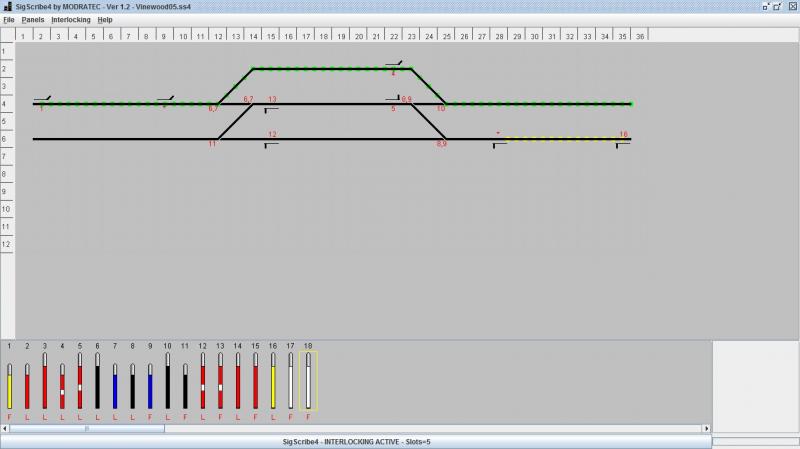
The letters below the levers show which are Locked and which are Free with the routes and signals set as shown. I am assuming a mechanical signal box but with colour lghts as direct replacements for semaphores.
I am not sure about prototype practice but I believe that splitting distants were not used much. I plan to use single distants.
As always, comments and suggestions are welcome.
Regards,
Brian
ECoS, Laptop, TrainController Gold v8
Brian
ECoS, Laptop, TrainController Gold v8
Posted
Full Member
You could have a "pseudo flowing curve" by using the Kato 15 degree curve … not like flextrack I know but it is a compromise. Alternatively there is a "Snap Track adapter" available which would/should couple to Peco equally well and allow your full flowing curve.
Just a thought and hope our feedback is useful… not quite sure why you would feel that you won't be able to exhibit but try anyway!
Regards
Trevor
Last edit: by xdford
Posted
Inactive Member
Time to update where I'm at.
The big decision remains: Go or No-Go with the whole scheme. I aim to reach that point before spending any significant amount of money, but there is a lot of work to do before then. It helps that I have lots of track and sixteen serviceable MERG electronic block controllers together with some home-built interconnection circuits.
Basic and non-negotiable decisions include a working mechanically interlocked lever frame; working representations of block instruments; push buttons to tap pre-set bell codes to the computer operated adjacent boxes; a minimum length of 1.5m for the main section of each block and a minimum of 0.25m for the stop sections; the capacity to have up to eight trains in service; the ability to reverse the direction of travel of the EMUs; TrainController Gold to drive the trains; modular baseboards; and plenty of room for scenic development, something I did not have on my 00 gauge layout. Inability to meet any of those requirements means cancellation of the project.
I have been playing on Anyrail with lots of possible track plans. Here are some of the more workable ones:

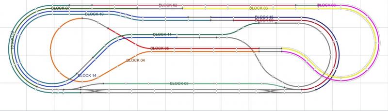
All of them are too wide for comfort, the first two are almost 4ft deep and the blocks are not quite long enough or too few in number. The one directly above is better, but still too wide and retains Peco points in the station. I have binned them all.
At the same time I have been following Trevor's reference to t-trak, but so far I have been unable to find any UK based t-trak clubs or interest. I have watched numerous videos of t-trak layouts and I have convinced myself that lots of scenic detail can draw attention away from the train set nature of the Kato track. I have decided to go for Kato trackwork throughout. It is quick, easy and I have plenty of it, including two scissors crossovers. A point driver circuit using an accessory decoder to control Kato points is easy and cheap to build. The ones I built previously are integrated with other control circuits and not re-usable, but I only need eight of them and they can probably be built as pairs on one board per pair. I will also need circuits to drive the signals from acc. decoders but these too are easy and cheap to build.
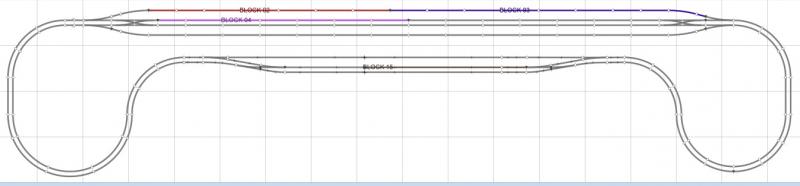
Harsh reality and considerations of space and practicality have pushed the track plan into a shape I have been trying to avoid; the British Standard double track oval, station at the front, storage yard at the back. I have had to give up the bi-directional storage yard but have retained the capacity for eight trains in the yard. EMUs can reverse direction in the station central loop platform, and I can run my goods train through, although it will always run the same way.
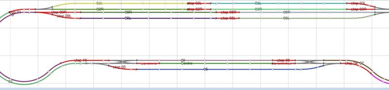
I have decided to go ahead with this track plan. Overall size is slightly more than 16ft x 3ft with a total area of about 50 sq. ft. Given the minimum block lengths, that is probably as good as I can get it. The end curves are superelevated with inside radius of 381mm. There is possibly too much area for scenery, that space will take a lot to fill it, but I'm beginning to organise some ideas for that. I feel that the station plan is too simple, although as it stands, and ignoring the two wrong direction crossovers included with the scissors, I will still need 14 operational levers and three levers for Facing Point Locks, 17 in all. The FPL levers are included in the locking but, as you can imagine, will not actually bolt the tiebars. The change from Peco crossovers to Kato scissors means that at one end the wrong crossover is set up in the SigScribe locking scheme. I will have to rebuild this scheme with the crossover reallocated and an extra FPL. I don't think that this has any bad effect on operation, especially regarding flank protection, but I am no expert - I hope some one can offer comments on the signalling scheme. The station is deemed to be old but the layout stripped back to allow for through trains and suburban commuter traffic only. Nothing else, and the signalling is intended to reflect this.
The scissors are there because I have had trouble with Kato #4 points, which permit crossovers with double track spacing. #6 points cannot fit that spacing but the scissors crossover, using #6 components, does fit in double track. Also I have two scissors in my goody box. The second crossovers will not be used, not signalled and not shown on the signal box diagram. In reality thay would be permanently locked Normal, but the Kato scissors moves all four points together. Using Peco crossovers instead would, I think, draw unwelcome attention to the difference in trackwork and would involve a lot of extra work in packing, ballasting and setting up servos to work them. For signalling my fall back option is to use colour lights from CR signals, but once I have decided to go ahead with the layout I will try a Dapol semaphore to see how it goes.
The track plan will not be committed until I start to build the baseboards, but unless some better suggestions come up I will go ahead with plans based on it.
Until now it has been "Too much talk, not enough action". The next steps are to correct that. I need to set up a test oval of double track including a scissors, and check that all my stock runs through it smoothly, both ways and in all directions. Assuming that is OK then I need to salvage or make new switching circuits to connect the block controllers and test the planned operation of the controllers. Next step is to arrange the switching of controllers to loops. After that I should be close to the Go or No-Go decision.
Regards,
Brian
ECoS, Laptop, TrainController Gold v8
Brian
ECoS, Laptop, TrainController Gold v8
Posted
Inactive Member
I went through the "formality" of checking out the scissors crossovers in a double oval. As expected, all the Kato units went through with no trouble. The kato steam 2-8-0 occasionally bumped a little. Then I tried my non-kato items. They jumped and bounced over the diamond, not actually derailing, but worrying. I have decided not to risk it, I'm going back to peco for the station pointwork.
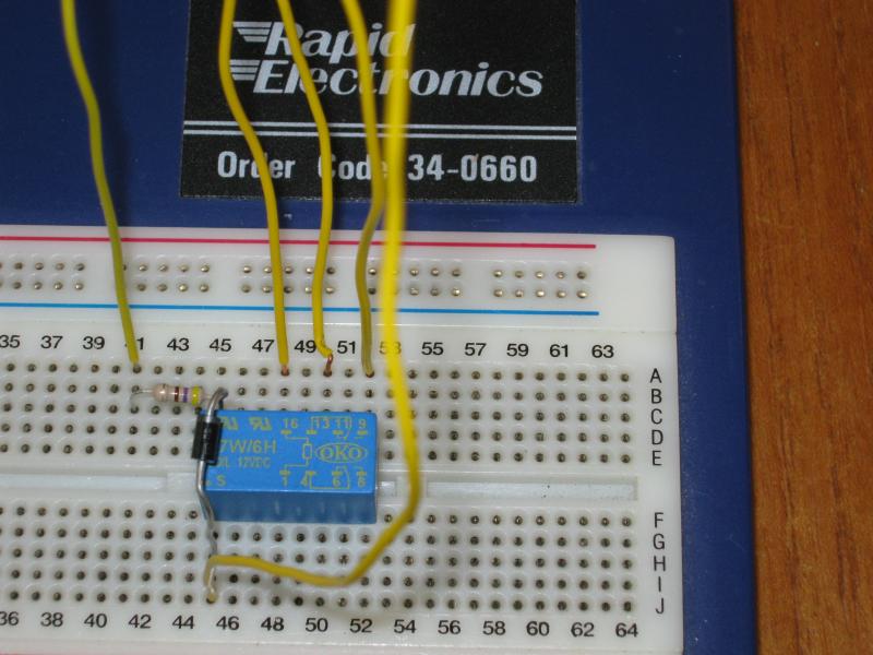
Next job was to test the detectors with DC. I am using a standard 16 port diode-drop module sending information on the s88 bus, first to the Ecos then via ethernet cable to TrainController Gold on the laptop. I set up four blocks on a simple oval, each block with a main section and a stop section, eight detectors in total. As you would expect, the detectors stop working when the DC supply voltage gets too low. I expected this to be around 1.4V but they carried on working down to 1.1V. At this level track voltage was just under 0.6V. The 2-8-0 stops at around 3 to 4V on the supply.
This is the rough and ready test setup:
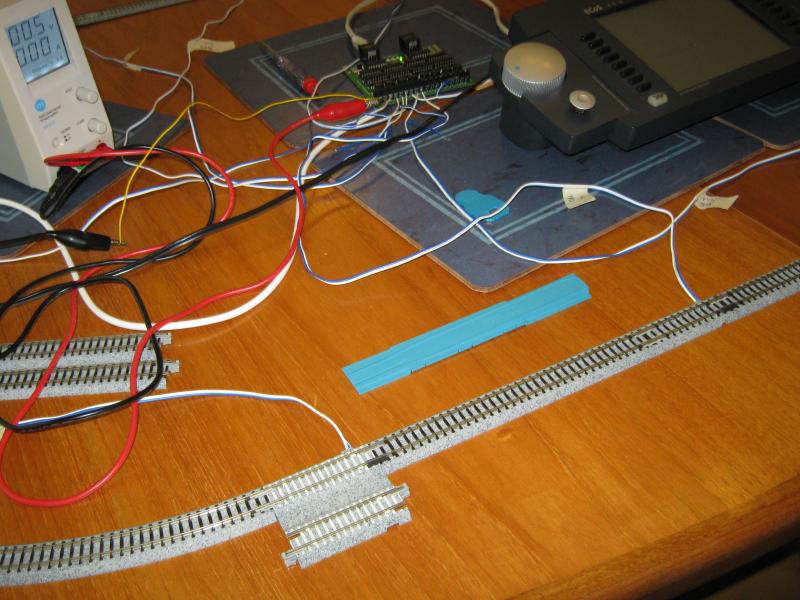
When I was satisfied with the detectors I set up the oval in TCG's switchboard. I have latched the occupancy indication so that even if the detectors go off the blocks retain correct occupancy information, and that checked out OK.
This is the switchboard:
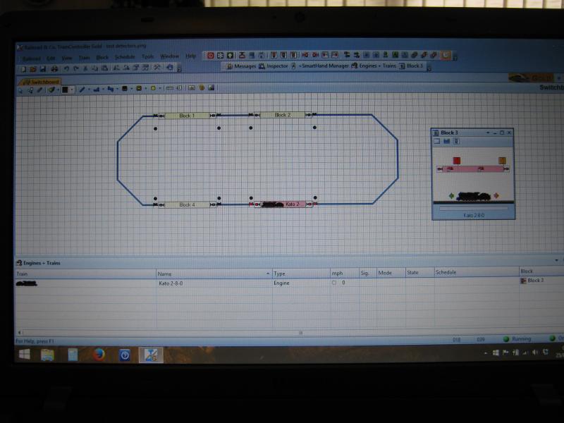
You can see above that all the detectors, the black circles, have gone off because track voltage is zero, but the block retains the correct occupancy indication, showing pink.
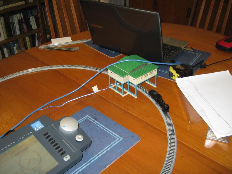
The last job was to check that TCG can track the train around. I was a bit concerned about this; there is no DCC signal being used and the DC control voltage is totally separate from TCG. For tracking, the train needs to be running on a schedule of some sort. I used Autotrain with drag and drop and drove manually along the route. Train tracking checked OK.
Regards,
Brian
ECoS, Laptop, TrainController Gold v8
Brian
ECoS, Laptop, TrainController Gold v8
Posted
Guest user
Posted
Inactive Member
Not much progress today, too many senior moments. I spent two hours looking for my electronics test board, then remembered that I lent it out about three months ago, then collecting together various other bits of hardware ready for the next stages and generally cursing when I couldn't remember where it all was. Over the next few days I will have to take the axe to my old (2008) Superbloc setup:
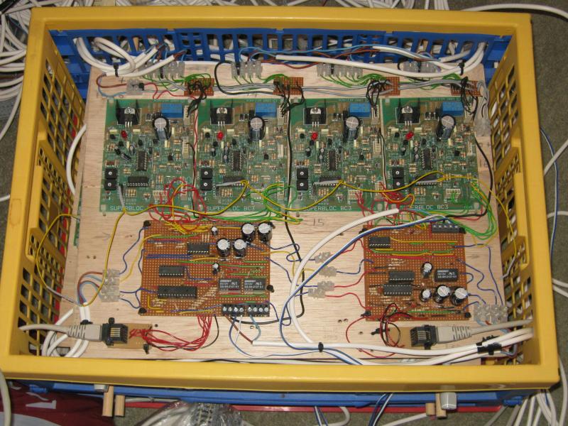
In this crate there are 16 MERG BC3 electronic controllers plus several circuits using picaxe chips to control the station points, with long wires to the various feeder tracks.
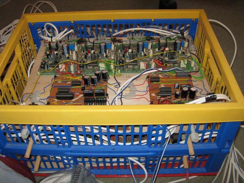
There are four layers of circuit boards, all wired together to give fully automatic block control. The BC3 controllers will be re-used, but there is not much I can do with the dedicated control circuits, other than salvage the chips. At least Christine will get her knitting needles back after seven years.
Regards,
Brian
ECoS, Laptop, TrainController Gold v8
Brian
ECoS, Laptop, TrainController Gold v8
Posted

Full Member
Sorry you couldn't get some of those layout plans to fit into your available space, some of 'em looked quite neat with the long runs and return loops.
Never mind, the electronics and lever frame in the current plan will keep you occupied for years… well it would me

cheers
Marty
Posted
Inactive Member
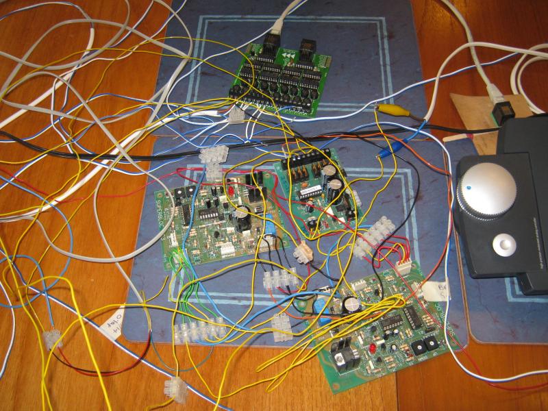
Nothing photogenic, just more green circuit boards and lots of wires. I have changed the 2-8-0 to a 6 car EMU for testing across the block boundary. The motor is in car 5, far away in this photo.
Two MERG block controllers are wired up to everything in sight, including an accessory decoder. Only five addresses in use at this stage, brake and stop for each controller plus one for the relay to drive my EMUs through the block boundary. I have amalgamated the four TC blocks into two longer blocks and connected them to TrainController, so I have four detectors in each block. It's not worth rewiring the detectors for testing.
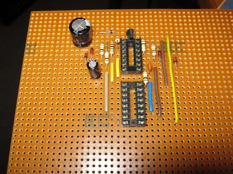
I started the testing with the intention of using my switching arrangements from the original Superbloc layout to avoid the need for lots of decoder addresses, no computer was harmed in that layout, and got as far as a test circuit on the breadboard:

Then I couldn't find my original stripboard layout or the original circuits, but I still have the schematics. These circuits used 556 dual timers and lasted less than a year before I replaced them with PicAxe circuits, but I had to start again with the 556 circuit. This is the hands-on method of circuit design, drop loose components into the board, then slowly re-arrange them into a compact layout.
As I worked on that design I didn't fancy building eight of them and I looked for an easier way. In the end I decided to accept an additional address per controller and set up this simple hardware solution, just a relay connected to the decoder output. I will not continue with the 556+switch circuit.
I can brake and stop the 6 car EMU by clicking on a "signal lever" on the TC switchboard, and tested it with a cycle schedule running five laps. Left to itself it laps at varying speeds (only two blocks makes it difficult) then brakes and stops on the fifth lap. Clicking the lever switch puts the virtual signal to Stop or Go and the train does as it's told. Not very exciting, but it's a start. I couldn't resist a little bit of interlocking so the signal cannot be cleared with the lever unless the block in advance is clear. Train tracking works properly so I will be able to use individual schedules for each train. It's slow progress but it's getting there. I have worked out the switching into the storage tracks, but I need to do more work on the switching in the station.
The elephant in the room is the overall size and number of the baseboards. At the moment I am looking at 12 boards of 4ft x 15ins. with an overall size of 16ft x 45ins.and I feel that is too much for such a basic track plan. Unless I can reduce the area and number of boards I am inclined to cancel the project. I have some ideas in mind that don't involve serious compromises: There is hope for it yet.
Regards,
Brian
ECoS, Laptop, TrainController Gold v8
Brian
ECoS, Laptop, TrainController Gold v8
Posted

Full Member
)
- Darius
Posted
Inactive Member
I have put a lot of time and effort in to the control system and reached a stage where I could build a working layout running automatically under Absolute Block rules, with a Modratec interlocked frame for the station. It would need more electronic hardware than I really want to use, but it would do the job.
The real killer is lack of space. To run my 8 to 10 car EMUs needs block sections at least 6ft. long and arranging enough sections into a satisfactory layout is just not possible in the space I have. Trying to achieve the impossible has been grinding away my enthusiasm for any railway modelling to the point that I have totally neglected Lancre Station.
2014 was mostly spent in equally fruitless efforts to get the Trainz sim working to my satisfaction. The thought of being able to build a layout of almost limitless size behind a computer screen was the attraction there, but the sim has so many drawbacks, especially with the signalling arrangements, that I had to give up on that too.
That leaves me with no alternative but to scrap any ideas for N gauge. I hope that going back to work on Lancre Stn. will start to grab my imagination again: I am planning to set up a signal box in TrainController to give manual control of passenger operations instead of the present fully auto working. Take "present" with a pinch of salt, the layout has not run for two years now.
If or when I start to make progress on Lancre I will revive that old thread, but this one is going nowhere.
Regards,
Brian
ECoS, Laptop, TrainController Gold v8
Brian
ECoS, Laptop, TrainController Gold v8
Posted

Site staff
Sorry to hear the N gauge project didn't work out, but Japanese N gauge's loss may well be Lancre Station's gain.
Ed
Last edit: by Ed
Posted
Full Member
Bob
Posted

Full Member
Good to hear from you……..you have been missed.
I am sorry that the Kato project hasnt worked out but I am delighted that you are re-visiting Lancre. Its one of the two YMR layouts I have ever seen in the flesh and I always thought that it had great operating potential and, despite the constraints, lots of scenic opportunities.
It will be good to have another guy to chat to about RR&Co:shock:
Best Wishes
John
Posted
Inactive Member
Bob, at least two of my EMUs have a radius restriction; from memory I think it is not less than 315mm. Right at the start I decided to give myself a safety margin and settled on a min. rad. of 348mm. I would stick to that, even with Peco track, so nothing gained.
The suggestion of a partial station, with the hidden part on the curve, is one that I had not considered, although I did work up a plan with no station, just a double junction in open country. I still have the problem of needing 6ft block sections, ideally eight in each direction, so length of run is the constraint.
It's significant that I don't regret cancelling the project, if anything I feel relieved to be rid of it. I came back to the computer just now with the intention of starting work on the Modratec Sigscribe program to have a first look at the interlocking for Lancre, and I am already thinking of building a frame using SPST switches before committing to Modratec. Now that the decision is made I am getting fired up again after a few months of lethargy and disinterest.
Regards,
Brian
ECoS, Laptop, TrainController Gold v8
Brian
ECoS, Laptop, TrainController Gold v8
Posted
Full Member
While the trade and many modellers seem to turn their noses up at four wheel vehicles. The various class 14- seem to have a charmed long life, suggesting that they work. also for short journeys they are not so uncomfortable. Certainly better than a bus on a crowded road.
back to four wheelers. I thought the idea was generally old hat. However there is a company making them in Argentina. Designed specifically to run on old poorly maintained track.
Kato I believe make some four wheeled powered bogies suitable for rail cars and trams.
freelance model railways and tramways
index02
index02
1 guest and 0 members have just viewed this.