Converting the Bachmann 3F to EM
Posted

Full Member
Using Brassmasters' Easi Chas Kit
IIRC Gibson pins are steel, US are brass. Anyway, I somehow lost a US bushing so had to re-do the outer rod holes (I'll still use a bushes in the center), by soldering in some brass tube and reaming out.Nice to hear you're making gauges, I expect yours will be perfect. A friend gave me some track gauges that I only learned later were home made. He later said, "Oh by the way, those gauges are out so you'll have to compensate".:shock: This after I'd built several points that didn't seem quite right. :roll:
John
John

Posted
Inactive Member
I make sure to use the lathe gauges to measure exact cutting distances plus I profiled a cutting blade to rail width.One is free to build any gauge or standard one wants if given a mind to.C&L have jumped their prices on gauges and given the sterling/euro exchange rate plus post.I was spured on to make my own.
Ah steel and brass a big difference in strength on those pins.
Keep it going,
Derek.
Posted
Full Member
John
John
Posted
Full Member
I thought I had things cracked this afternoon but when I applied power to the chassis it sort of ran but in short order a coupling rod knuckle joint failed. :twisted:
My thinking is that there are two things (at least) going on:
1) My quartering is still off and
2) The coupling rod knuckle design is inadequate.
So, had a quick think.
First, I need rods. The Bachmann rods could be re-used and I took them off to see. However, they are not fluted, oversize and the bosses are huge.
I then thought, do I have any rods from elsewhere? Well by a stroke of luck I found some Jinty rods from a previous build that, amazingly, are exactly right!:cheers Well, maybe not so amazing because this wheelbase was fairly standard on quite a number of LMS locos.
Next, I will dig out some Markits wheels to see how they do. I am thoroughly fed up with these US wheels.
John
 Last edit: by Brossard
John
Posted
Inactive Member
If its on a curve one might look at wheel sideplay clearance as well.
Good luck with the detective work.
Derek.
Posted
Full Member
No, I think I'll bite the bullet and see how the Markits do. I've remembered that I have a SE Finecast 4F that I bought second hand for, I think, $50. It has Markits (well probably Romford) wheels.
Actually, it's about a wash whether you go the EasiChas route or the traditional chassis kit. It's roughly 10.00 cheaper for the latter and that includes a motor and GB. I think it's a great pity not to use the RTR drive train but It seems to me that that the chassis kit route is less risky. You can still buy detailing etches separately from Brassmaster's if you want, but I've found that Bachmann's detail is pretty good anyway.
John
Last edit: by Brossard
John
Posted
Inactive Member
Those fine scale coupling rods don't give one much metal to work with and soldering knuckle pins is a very delicate job.
Sorry again to mention rivet pins.Those Gibson medium length valve gear ones were what I had in mind for a knuckle pin.Its only a thought and they might not suit the job.It seems a pity to have invested in US wheels and not be able to use them.
Oh the joys of building loco,s.
Derek.
Last edit: by shunter1
Posted
Full Member
I have some brass rivets, so those might have been better.
As I was looking for, and at, the Markits/Romford wheels, I noticed an anomaly. 3Fs (and I think 4Fs) had two sizes of wheel depending on when they were built. Most of them had 5' 3" (21mm) wheels but a small number of early locos had 4' 11" (20mm) wheels (it doesn't sound a lot but the difference is marked when they are side by side). The anomaly is that my 3F was fitted with 20mm wheels and the US wheels are also 20mm, yet the number on my loco is in the 21mm wheel dia range. I have a set of both so I'm going to fit the larger wheels. These are from that old 4F model and did require the flanges to be turned down.
Hopefully, we'll get to a point today that confirms my ideas.
John
John
Posted
Inactive Member
Thats all I can gather at the moment.
Cheers,
Derek.
Last edit: by shunter1
Posted
Full Member
I have to admit to an error in my statement above, coming from not doing the math thoroughly. The wheels on the 3F are, in fact 21mm, so correct for all but the earlier members of the class.
The wheels I took off the old 4F, are 21.6mm or 22mm nom, and actually scale to 5' 5". It's those darned fractions and guzzintas :roll:.
All 4Fs were built with 5' 3" wheels (and I checked every source I have), and my Bachmann 4F comes out correct there.
So, back on track with some Markits 21mm wheels.
The other thing I looked at was the Bachmann 3F and 4F wheels, flanges in particular. Difficult to measure but appear to be ~ 0.6mm thick, very much in line with Markits and EM Spec. I tried a wheelset on an EMGS axle and there does seem to be generous side play between the flanges and inside of rail. They are still pretty thick but less so than older wheels and come out at ~2.6mm. Romford and Markits are 2.45mm thick, while the US wheels are 2.2mm.
My point, probably lost in all those numbers, is that newer Bachmann wheels could feasibly be used for EM, if only they could be induced to grip the EMGS axles. Depending on body and splashers, the wheel fronts may need thinning.
John
John
Posted
Full Member
Dare I say, that we are on the home stretch now. My next task will to fit wipers and complete the tender (the loco won't run without it).
John
John
Posted
Inactive Member
I think there is a loctite glue designed for metal plastic joins,Could be 501 will have to check.
Bachman wheels are excellent rollers a little thinning and they would be grand.
I am building a comet 2 stage gearbox at the moment.I need to get some new soldering iron bits for my 50W job.The one I have is to big for those fiddle jobs.Great for outside jobs on the metal but getting into tight corners another matter.
Cheers,
Derek.
Posted
Full Member
I had to go to C&L for the 603. I hunted high and low over here for sleeve locker but never could find it. Thread locker is easy to come by.
I need to do a check with the body before going any further, I hope there's no foul. Otherwise it will mean everything has to come off and the wheels thinned. :roll:
I'm very interested in how you get on with your gearbox.
John
John
Posted
Inactive Member
Your axle box system should allow assembly of wheels ready quartered before instalation. Thread the boxes onto the axle.Quarter the wheels and slide axles and boxes onto the chassis then fix axle boxes in place.A quartering jig could be used for setting up the wheels before instalation to the chassis useing that method.?.
Cheers,
Derek.
Last edit: by shunter1
Posted
Full Member
Yep, I agree with all you've said. I can get the wheels quartered OK, but getting them to maintain quarter is the challenge. Loctite 603 is the answer, but getting it between the wheel bore and axle, after that, is another question.:hmm
I've been doing a trial fit of the body. Very tight clearances! I ground away at the inside of the splashers. The footplate is Mazak, while the splashers themselves are plastic (Brassmasters offer replacement brass ones for the 3F and, in Jan., the 4F). I don't mind if the wheels touch plastic, but contact with the Mazak is a no-no. I filed down the grease points on the rods and even replaced the crankpin washer on the center drivers with a 16BA nut to gain ~ 0.5mm.
Not sure that springing is all that good an idea for EM. In P4, wheels are significantly thinner so they'll clear the footplate easily.
John
John
Posted
Inactive Member
Loctite have introduced a new glue 4090.Its got high structural strength and with the fast set abitity.It glues metal,plastic's etc.Thats the one I am going to get next.
Tight clearances are the bain of changing gauges.P4 you have smaller flange depth and thinner wheels.Have you any way of turning down the wheel threads to give a better profile ? plus more clearance.One needs of course some decent sideplay for the less than prototype radius track curves.It all gets a bit complicated.
Hope you can fettle those splashers and footplate pests.
Cheers,
Derek.
Posted
Full Member
I will look for that glue, but it seems 603 works well enough for the moment.
I can turn down flanges using my Dremel and a file, but I wouldn't want to touch anything where concentricity is critical.
Part of the issue I could see was that at full upward travel, the rod grease points and crankpin nuts were frighteningly close to the footplate. The brake hanger wires were also very close to the wheel flanges, so I've thinned those as well.
I had a brainwave after my last post and that was to solder some brass strip to the top of the bearings as a snubber to limit upward travel. I'll only get about half the travel but I'll have better clearance at the footplate. For the splashers, I'll paint on some nail varnish just to make sure there is insulation.
John
John
Posted
Inactive Member
You need a lathe do do accurate facing off of wheel treads any of your friends have one?.
I have the Comet gear box finished my new soldering iron bit made of brass,Not my first choice but I did not have any PB of the right dia. It works fine if well tinned.
Gearbox axles are nice and true with no slop including the gear carrying axle.Just need to fit spacing rings and gears/motor.
Some photo,s hope you don't mind.
Derek.
Posted
Full Member
You're right about needing a lathe to reduce the face of a wheel. It can be done with the Dremel and an assortment of files, but that is tedious.
Thanks for the gearbox pics. Now I want to see the gears in and backlash established. This it all where it went horribly wrong for me.
John
John
Posted
Full Member
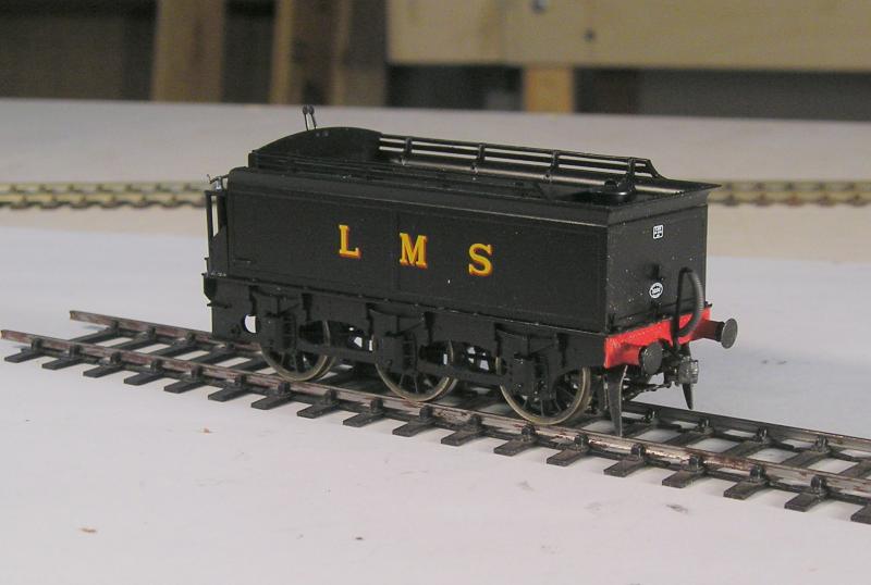
The brakes, the weakest part of the Bachmann model are now in line with the wheels and, of course, it's sprung.
I used a Markits vacuum pipe, the Bachmann item seems wimbly to me, although I expect I'll be told they're scale.
The coupling is further in than usual but I'm taking advantage of the sprung buffers. I've done some testing on various wagons and it works, as shown here:
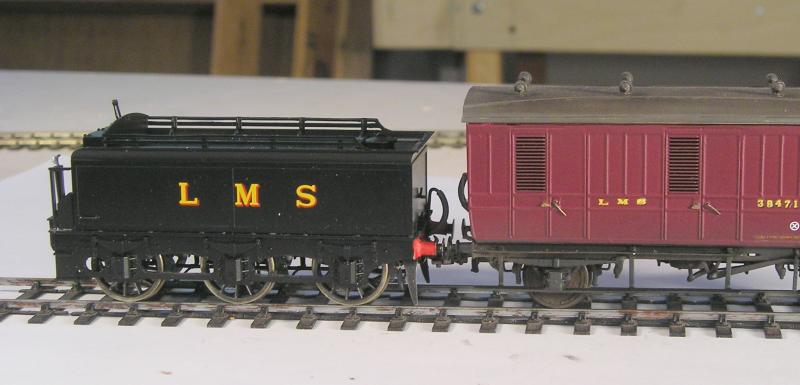
The buffers are nicely close together and when propelling through a point (the acid test), compress prettily without locking up.
John
John
1 guest and 0 members have just viewed this.