CODE 100 ELECTROFROG TURNOUTS
Posted
#181013
(In Topic #10220)

Full Member
HOW TO GET THEM TO WORK


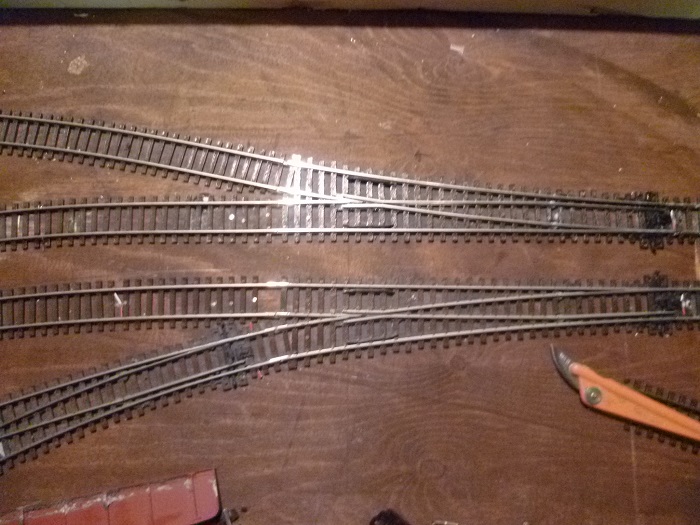
I've got two right hand and two left hand med. rad. electrofrog turnouts linking two tracks together. As you can see I've put plastic fishplates on the "V" of the turnouts and all track and turnouts have drop wires soldered. When all linked together my test buzzer rings out a fault, when i place the tester probe on one line of the track it buzzes through when I touch the opposite line on the same track? this should not happen. I've checked the wiring under the baseboard and that is ok so am I putting to many feed wires on the track or have I not put enough plastic fish plates on the turnouts. Please don't recommend reading some ones wiring article because the confuse me. Thanks to any one who can advise me.

Posted

Inactive Member
Posted
Full Member
Posted
Inactive Member
Posted

Full Member
I think you have a wiring problem rather than a joiner problem. How do you switch polarity on the frogs ? Your photos don't show any switching but, with electrofrog points, you must do this otherwise you'll get a dead short as soon as you try to use the crossover.
Looking at the shot where you've lifted one point, the upper rail of the upper point is wired red. When you lay the point down, that red rail will meet a black rail ……………unless you've changed colour coding on the lower track. "Normal" wiring practice suggests either outer (or furthest from you) or inner (closest to you) rail red, the other black - regardless of how many tracks you have.
'Petermac
Posted
Full Member
Posted
Full Member
If you're running modern diesels with all wheel pickup, then no problem but, as soon as you try to run an 0-6-0 tank engine over insulfrogs, particularly at slow speed, they'll stutter and stall.
I was a diehard insulfrog man myself - for exactly the reasons you're fed up with electros - then, having wired my first one (with lots of help from the guys on here), it clicked and I wouldn't go back to insuls for all the tea in China. ;-)
I think, but I'm not certain, that for just running straight through, you don't need frog switching but you do need to remove some of the factory fitted link wires underneath.
They look like Peco points so the leaflet that comes with the point, shows you a tiny wire underneath bridging a pre-cut gap in each of the rails. Just grab this with pliars and pull it off. You then provide power to the long silver wire (folded under the frog rails) to power up the frog. It's this wire that needs switching.
You said it wasn't necessary (switching) for straight through running. You're right - it isn't, but why would you want to just have straight through running …………….? :roll::roll::roll:
'Petermac
Posted

Inactive Member
Then you will need to switch the frogs, or the locos will stall.
Max
Port Elderley
Port Elderley
Posted
Full Member
Posted
Full Member
You haven't said what type of loco you plan to run - steam or diesel - "pre-owned" or newly manufactured ?
Insulfrogs - sometimes called "dead" frogs or electrofrogs - sometimes called "live" frogs - which type ?
 hmm
hmmAs Max said, insulfrogs are easy-peasy but there is a price to pay for simplicity. That price lies in the "dead" frog - i.e. a frog with no power. If all the loco wheels are on this dead section at the same time, the loco will stop ! Even if one wheel is on a "live" section, but it's slightly dirty, or the pickup isn't what it should be, it will at best, stutter. At worst, stop.
There is no "dead" frog on electrofrog points so the stopping doesn't happen. Of course, both your track and wheels need to be clean in each case.
Wiring electrofrogs isn't difficult but you do need to switch the frog polarity somehow. Many electric point motors have a switching facility already built into the motor. If you're "hand throwing" the points, then you'll need an electro-mechanical method of switching. Micro switches are probably the easiest option although it is perfectly feasible to make your own switching method via a push-rod and contact as you throw the point.
Decide on your stock and, if it's current range diesels, they'll have multi wheel, if not all wheel, pickup so insulfrog would be fine - and easy. If your stock is steam, short wheelbase tank engines etc., then I'd recommend you try to get your head around wiring the electro frogs. You won't be sorry - I promise !!! ;-)
'Petermac
Posted
Full Member
Posted

Site staff
http://brian-lambert.co.uk/Electrical.html#live
it should help to understand Electrofrog wiring
Ron
NCE DCC ; 00 scale UK outline.
NCE DCC ; 00 scale UK outline.
Posted
Full Member
Posted
Inactive Member
The pic below should help you

 Last edit: by 60019Bittern
Posted
Full Member

Thankyou, thankyou for your help. This crude plan just displays a little of my electrofrog problem. My layout being 12 foot by 8 foot a double track running together around the table and at one side I shall be putting some sidings to run into and around a station. The plan above shows where the sidings will go….any better ideas will be welcomed. thanks again
Posted
Inactive Member
On your drawing, on the left hand side on the inner circuit you have a point heading to sidings followed by a point onto the crossover.
you will need to put insulators in between the two points as you have the turnout sides facing each other. I'll try and modify your drawing to show you what I mean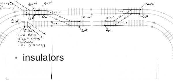
That ought to work although you could do away with one of the two feeds on the outer circuit left hand side and again in the middle of the inner circuit
Last edit: by 60019Bittern
Posted
Full Member
Posted
Full Member

c run around section.
With this message I've added a rough sketch of my table top with the area of board I need some ideas on, that is how to add a small station, some sidings either side of the main lines and what to fill in the section to the left of the sketch. There are no measurements I know but if required I will add them. My idea was to put a diesel maintenance depot in the section to the far left, sidings in the middle section in front of the upper level track and a curved station to the right of the drawing, Ideas would be helpful.
Posted
Full Member
At first reading, it sounds as if you're trying to fit a quart into a pint pot ………(if you know those volume measurements :roll:).
It's worth bearing in mind that a point in "OO" Gauge, will require around a linear foot (30cms) to allow for clearance etc. If you have 4 sidings, you'd need at least a 3 way point plus one other - that's an absolute minimum of 60 cms - just for the points !!
If you're in "N" Gauge, then the distances are about half …………..:thumbs
Overcrowding is one of the most common mistakes with new layouts. :roll:
'Petermac
Posted
Full Member

IMPERIAL MEASUREMENTS PRETTY WELL SPOT ON, METRIC MEASUREMENTS JUST A QUICK GLANCE AT TAPE MEASURE.
Hi thanks for the reply, yes I do realise I might be asking for to much. Hopefully the measurements added will give you a good idea of what area I have got to play with. At the end of the day if all that I can fit in in this space is ??, I don't mind as long I can fully detail it and run my modern image stock. If you or some one can suggest something for the small area top left…brill.
1 guest and 0 members have just viewed this.