New part work
Posted
Inactive Member
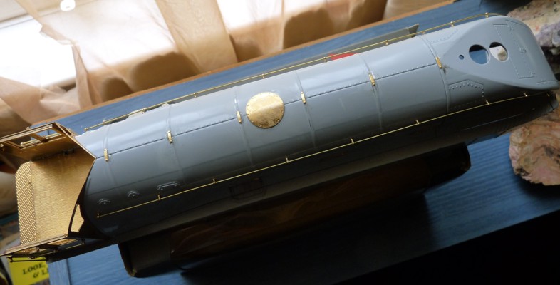
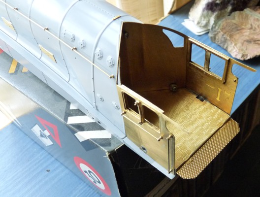
Part 4, Cab details.
Tip 1. When building up the cab window bits things get really fiddly so I would suggest making up some sort of jig to get all four layers lined up correctly. Also take the arm rests off. They get in the way. I will replace them later with a bit of plastic strip. Wait until later to fit them to the cab sides when they are set.
Tip 2. There are four miniscule little brackets (parts no E134 and E135) I would suggest soldering the lower ones in place before you mount the window bit and smooth everything down afterwards. To say they are fiddly otherwise would be an understatement. They are nigh on impossible. Fold up the ash guards as per the instructions then fit the upper brackets. (Even more fiddly). They say the ash guards can be made to hinge but it would take a genius to make them work. I ended up super-gluing the whole lot together.
Tip 3. On my cab etching there were no holes for the top handrail knob to fit into. Drill these carefully. Fitting the handrails is a simple job but again I decided to fit one of the knobs firmly on the wire before fitting the other one when the lower knob had set.
Fitting the cab to the rest of the body work is also a bit tricky. I decided to do away with the angled brackets and just screw the body straight in as is.
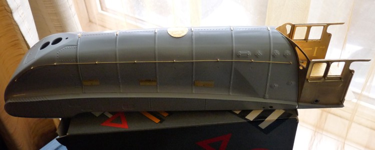
Part 5 Boiler details.
These include boiler band top clamps and side doors along with the dome access plate. The boiler band clamp etches are a bit on the small side and are tricky to hold when trying to file off the remainder of the holding nips where they were attached to the etch. They were even more difficult to hold in place whilst gluing them. Curve them first over a hammer shaft or something does make it a bit easier. The dome cover plate is also bent before attaching. The side doors on the body are fairly straight forward but study the instructions carefully to see where they go. They are handed and different. Once everything is set you can drill out the holes for the handles with a 0.6mm drill in a pin chuck.
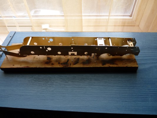
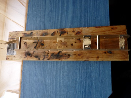
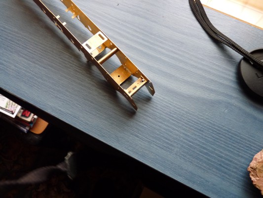
Issue 6 parts are the first side of the chassis. Next week is the other side so will go through that set up next time as it would be better to build the chassis frames in one go.

Posted
Inactive Member

That's it for now. More later when it's been done
Posted

Full Member
:cheers
John
John
Posted
Inactive Member
 Last edit: by 60019Bittern
Posted
Full Member
:doublethumb
John
John
Posted

Full Member
'Petermac
Posted
Inactive Member
Posted
Inactive Member
Next issue is the rest of the spacers and the 6 top hat bearings.
Here's the pics.

That's it till next week.
Last edit: by 60019Bittern
Posted
Full Member
John
John
Posted
Inactive Member
Posted
Full Member
I'm staggered to think that someone would think that gluing would produce a good result. I think soldering is so much easier than glue.
John
John
Posted
Inactive Member
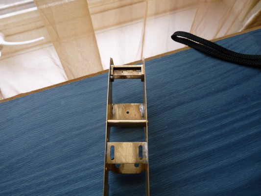
There are three spacers that need fitting and these went in with no real problems. Just make sure that they are the right way around. The one at the rear is the one where most care is needed as it does have to be put in in a certain way. The flange on it must point to the rear and be at the bottom. The slots near the top that are not used at the moment must be kept clear. It's a bit fiddly but it does work.
Next week it is the first of the outer chassis parts so will put some pics up then when it is fitted up.
Remember if you are soldering it all together sand the parts first to get rid of the lacquer. Makes life a lot easier.
Last edit: by 60019Bittern
Posted
Full Member

'Petermac
Posted
Inactive Member
Posted
Inactive Member
The rear spacer. Note the flange at the bottom facing rear.
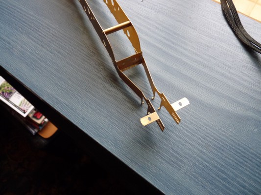
Another view of the rear spacer.
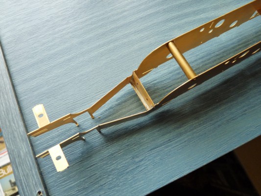
The remaining front spacers. The one with the hole in the middle has to have the two small holes on the sides facing to the rear.
Another view of the front spacers.
I've still got a bit of cleaning up to do, but that is a simple enough matter.
That's all for now folks. Catch you all again next week.
Last edit: by 60019Bittern
Posted

Full Member
Posted
Inactive Member
One thing about 7mm you can see most of the bits you have to work with.Looking forward to further installments and thanks for shareing.
Derek.
Posted
Inactive Member
Jimmy
I use the good old resin cored stuff along with Carr's red label flux. My iron is one of those cheapo 60W ones form the local tool shop. For the solder I have a mate who used to work in a supplier and he got hold of a 2.5Kgram spool for me. Have enough to see me through this life and the next. It's a tin/copper/lead alloy (proper solder).
Shunter1
Yes it is nice to be able to see the bits, which is helpful. I still manage to burn my fingers though now and again. I also build in 4mm, which a times can be a bit of a pain.
Last edit: by 60019Bittern
Posted
Guest user
An excellent thread. Good to see a blow by blow account in order to understand it all. Looking forward to the next episode.
Cheers
Toto
Posted
Full Member
As for flux, I've found that any phosphoric acid type (like Carr's, only I use Green label) will work. The drawback of course is that the work must be washed to stop corrosion.
For electrical work I have used a 60/40 solder with separate rosin flux. The trouble with rosin is that it leaves a sticky mess but I believe it cleans up with methyl hydrate (happy to be corrected on that if I have it wrong). Another alternative flux to consider is plumber's water based flux (don't get the petroleum based stuff, it's very hard to clean up) which is non-corrosive. This stuff works on all solders (I've experimented), even 70C.
60/40 solder melts at around 188C. I mostly use 145C solder from C&L, but I'm running low. I'm also running low on Green label flux and it can't be posted. A local retailer (only about 800km away) stocks Gaugemaster non-acid flux, so I'll be giving that a go.
I bought myself a temperature controlled soldering station with tip temp. feedback about a year ago. It's rated for 50W and I currently have it set for 340C, which works well (rule of thumb from Tony Wright is to set the tip temp. to twice the solder melting point). It was a bit dear, but if you do a lot of soldering, a worthwhile investment.
John
John
1 guest and 0 members have just viewed this.