LMS Pull Push Coaches
Posted

Full Member
Finally!
I'm surprised you gulp at the painting John. I'd have thought if you could achieve that standard with brass and solder, painting would be a walk in the park …………….:roll:Your throw-away comments about this or that being "a bit of a fiddle" belie the fact that it was probably nigh on impossible ………:???::???:
'Petermac

Posted

Inactive Member
What arrangements did these carriages have for people to move from one to the other in transit?
Max
Port Elderley
Port Elderley
Posted

Full Member
Max, these are Non Corridor, so once you're in a compartment, that's it. No lav either. Mind you, these Pull Push trains tended to be used on branchline service with frequent stops.:Happy They're sometimes referred to as suburbans, bringing people from their homes in the 'burbs to larger stations for transfer to trains going to major centers.
John
John
Posted
Inactive Member
Max
Port Elderley
Port Elderley
Posted
Full Member
I do plan to have a corridor train but it will be short. The code for these kinds of trains is "Ordinary Passenger" with a lamp at the top center of the loco.
John
John
Posted
Full Member
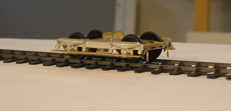
I've added full length stepboards and guard irons. I also replaced the bar between the W irons with 1mm phosphor bronze strip.
Looking at the pictures I have, there seems to be considerable variation from coach to coach - some having only half a stepboard.
I used a strip of scrap brass, carefully marking out the position of the axle box cutouts and using my Dremel to make the cutouts. These were dressed with fine files. 0.020" holes were drilled in the bogie side casting just below and either side of the axle box. 0.020" wire was soldered to the stepboard checking the hole location as I went. When done, these were fixed with cyano and the protruding wire snipped off and filed. Even so, I ended up with things being too wide so I used a grinding wheel in my Dremel to gradually remove material until the width was about right. A flat file was used to ensure the edge was smooth.
John
 Last edit: by Brossard
John
Posted
Full Member
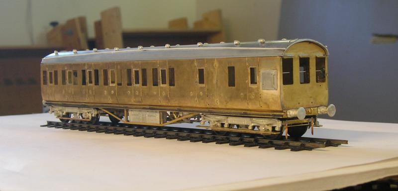

You can see the front bogie with stepboards and guard irons. Duckets were sweated on using a mix of 145C and 70C solder. Something I hadn't done before but it worked out OK, once I got the iron temperature right.
Buffers are now on.
There's a handrail for the driver inside the cab.
Alarm gear can be seen on the rear end as well as grab rails.
Note the hook for coupling. I'm going to use Tony Wright's system. I've used it before and it works extremely well.
I will point out some reading material that I dug up yesterday.
First, there is Mike Clark's (of Masokits) article in MRJs 48 and 48 (1991), on building some LMS coaches. He provides info on some extra detailing of the underframe (like wiring for the dynamo and feed pipes for the vac. cylinders) and there's even super detailed drawings of a brake and coach underframe - there are differences. I had a go at reproducing some of these details although they're not really visible in the photos.
The other is Andrew Lambert's article in MRJs 80, 81 and 82 (1995), again on building an LMS coach. I am quite inspired by his approach to the interior so will look into that.
These are well worth a look if you plan to try a Comet kit. I'm rather enjoying it.
I still have some plastic bits to stick on (wot no solder!?) - the above door ventilators and alarm gear box.
John
Last edit: by Brossard
John
Posted
Full Member
 thumbs
It's when you see something like this that you realise what's actually missing on the RTR offerings - good as they are nowadays.
I'm now holding my breath ready for the painting / lining ……………..:cheers
'Petermac
Posted
Full Member
I too am holding my breath wrt painting. First though, I need to rough in the interior.
John
John
Posted

Banned
Cheers, Gary.
Posted
Full Member
I've said before that the ability to make brass kits will open a whole 'nother universe of modelling possibilities.
John
John
Posted
Full Member
It was only after all that, that I checked the glazing sheet provided in the kit - 0.020" thick :roll:. So I had to add a second layer of 0.010" card.
Anyway, after all that, here is what I got:
The idea is to use the cavity to trap the glazing. The droplights add a bit of complication, but we'll do what we always do…make it up as we go along.
Note that I have fixed the ventilators.
The next step is to take more 0.010" card and cut out the windows. I fortunately have a pair of spare brake sides from a previous aborted effort. I marked out the windows using the sides as a gauge and then, laboriously, cut them out. This worked out quite neatly.
The resulting inner side layer was glued on:
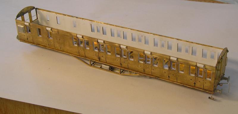
The inner windows are slightly oversize right now. The plan is to trim to size after the glue has hardened.
John
Last edit: by Brossard
John
Posted
Full Member
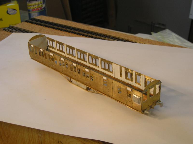
You might just be able to make out that I represented some door detail with a central scribed panel and 0.010" x 0.040" strips as a door frame.
The floor was marked out and holes made for the nuts and vac cylinder nub. 0.030" strips were glued under the floor to space it above some of the other stuff that got soldered on during construction.
I then turned my attention to the seats. These come as ~4" strips and must be cut to length. Being me, I made it more complex than I needed to. Having a look through my bible for LMS Coaches I saw some very good drawings and photos of compartment interiors. I thought it notable that even 3rd class were quite luxurious with wood panelling and plush seats. I also noticed that there are upholstered end boards for the seats with a headrest. I represented these with some plastic card cut to about the right dimension. I can paint the seat assemblies the same colour.

Just a few examples of the seats. I still have a bit more work to do.
John
Last edit: by Brossard
John
Posted
Inactive Member
How many more did you say you have to do?
Max
Port Elderley
Port Elderley
Posted
Full Member
John
John
Posted
Full Member
Posted
Full Member
Misjudged !!! :shock::shock::shock::shock:I misjudged the quantity of endboards so I had to make more. …………………………………………
I thought this was a piece of precision engineering, not simple "judgement" …………..

'Petermac
Posted
Full Member
I also cobbled up a driver's control panel yesterday based on a Cl 108 DMU that I have. No idea how close it is to the original. Even the gurus on RMWeb haven't been able to answer the question.
John
John
Posted
Full Member
As the compartment/floor nears completion, my thoughts turned to compartment detail in the form of those prints we used to see above the seats. I had a rummage but couldn't find any Tiny Signs. I googled the search term and lo and behold I lucked out. There's a site for Claude Buckle who painted the very thing for BR. Beautiful stuff too. The cool thing for me is that the site lets you copy the paintings as JPEG.
http://claudebuckle.co.uk/carriages/carriages.php
I've manipulated them using PowerPoint to give me a sheet of really small prints, about 5mm high (which may yet be too big, I'll have to try).
I'll demonstrate how I make frames for them.
John
John
Posted
Full Member

'Petermac
1 guest and 0 members have just viewed this.