Dunworkin the vision
Posted
#175695
(In Topic #9930)

Full Member

Posted
Full Member
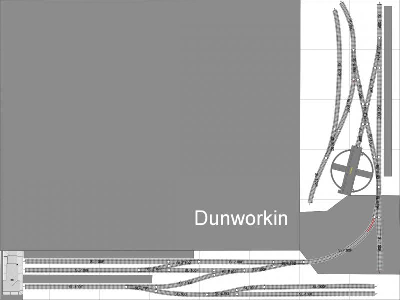
Given the presence of the turntable I guess you will be operating in the steam era?
I was wondering how you were thinking of releasing the locos once they have pulled into the platforms? On the top double track the two cross over points could be moved closer to the station building end of the platform. This would allow locos to uncouple and run around the train. The same could be done with the single line platform, by adding another point to create a run around there too. Of course you may be using push-pull trains, or even DMUs, so these comments may not apply.
Bob
Posted

Inactive Member
Max
Port Elderley
Port Elderley
Posted
Full Member
 Last edit: by Sapperzane
Posted

Full Member
Cheers MIKE
I'm like my avatar - a local ruin!
I'm like my avatar - a local ruin!
Posted

Full Member
Mike
Pig Hill Yard - a small Inglenook shunting layout for my boys, in 00.
Pig Hill Yard - a small Inglenook shunting layout for my boys, in 00.
Posted
Full Member
What is the purpose of the two sidings? Are they there for an operational reason, or just because they could be fitted in? If the latter, put yourself into the position of the railway company building the line. Track is expensive and has to be maintained. Are you going to install extra trackwork for no operational reason? Also, any train occupying the two lower sidings will be trapped if there is a train at the platform. I would reverse the point at the platform, moving it further away from the platform. Run one line into the platform and the other into a headshunt from where the sidings could come off in much the same position as they are at present. By doing this, trains could enter and leave the sidings whilst there is a train at the platform.
Re the upper part of the plan. What is it you are trying to depict here? Is this a motive power depot? If so, why the need for a platform? If this is another station, the trackwork looks very complicated. Every railway company laid out its stations based purely on operational need. They didn't just fill any available land with lots of track for the sake of it, which, unfortunately, appears to be just what lots of railway modellers do!
You could do no better than to copy the track plan of actual real-life stations. By doing this you will ensure that the trackplan is tried and tested and that all train movements are in accordance with what the prototype would have done. There are plenty of model railway books on the market containing good operational plans. Might I suggest that you have a look at that good old standby '60 plans for small railways' by the late C.J Freezer?
Terry
Posted
Full Member
Posted

Banned
With some of the questions raised about the track plan, I can understand where and why they are being asked. With some of the hints mentioned, I took your plan and drew over it to make it possibly more feasible for an operating railway. Not too many changes, although I did redesign the track on the right hand side to be a little more prototypical. Now, I'm not telling you to cross your T's and dot your I's and it may not be what you are after either, but I hope that it may help. I also don't know what you had intended for the blank section (on your right hand side plan), left of the sidings, but I did chew up some of the space ! Remember, less can be more with model railways and that Rule 1 always applies ! ;-)
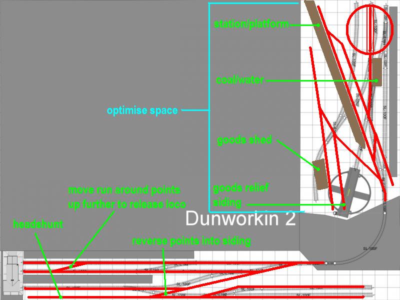
Hope the explanations above help.
Cheers, Gary.
Posted
Full Member
Terry
Posted
Full Member

Posted
Full Member
With regard to the upper station, you now have to ask yourself whether there is enough length to get a train into the loop to allow its loco to run round to get to the other end. Don't forget that every two tracks that converge have a fouling point i.e. because of the width of the passing vehicles they will collide until the tracks are sufficiently far apart to allow the two vehicles to pass each other. I must say, the loop looks awfully short to me.
Keep at it, you'll get there in the end.
Terry
Posted
Full Member


Cheers MIKE
I'm like my avatar - a local ruin!
I'm like my avatar - a local ruin!
Posted
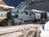
Banned
here is another plan. It measures 500 x 1800, which I think is the size of the board you have on the right hand side. To fit most aspects you have included on your plan, the curve back to the lower/main station area has been lowered closer to the back/bottom edge.
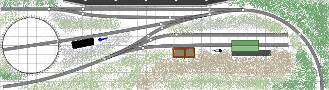
The turntable I used is Peco and not the Dapol (?) as on your original plan. The black rectangle is the coal stage, blue is the water tower, two tone brown, possible cattle dock, black pointy thing is the yard crane and ofcourse the two tone green shed is the goods shed. The station is overhanging the plan a little, but there should be another 50mm on the top and bottom of this.
Cheers, Gary.
1 guest and 0 members have just viewed this.