Rail profiles
Posted
#189036
(In Topic #10588)
Full Member
Differences between Code X and Code Y
Hi GuysDoes anyone have, or know where I can find, measurements for rail profiles in 00?
I want to use Peco flextrac on a street tramway but need to custom make pointwork so I need to know what to design and build too.
Thanks in anticipation
Regards
Jim
Because, except in some unfortunate circumstances, trains did not run on town centre streets

Posted
Full Member
"so I need to know what to design and build too." Sorry Jim, I can't work out what you mean here. Can you clarify this bit?
Terry
Posted
Full Member
Thanks for the reply.

I am trying to find out the height of the rail, the width and depth, the web width, the total height and the height and width of the foot so that I can make up a profile of the Peco standard rail and see if I can find something close to tram rail so that I can build my points and junctions to match it. I'll probably end up at Shapeways minus an arm and a leg but I still need the profile of the rail.
You said
Ummmmm Is it me or would that not equal a 3/4 or 1 inch high rail?Peco uses code 75 and code 100 rail. The numbers relate to a rail height in hundredths of an inch.
Once more thanks for the insight.
Regards
Jim
Because, except in some unfortunate circumstances, trains did not run on town centre streets
Posted
Full Member
Terry
Posted

Inactive Member
Which code?
PECO Model Railways, Publications & Pecorama
Some products . . .
Peco Streamline Finescale
Some technical stuff . . .
http://s374444733.websitehome.co.uk/code75/index.htm
Cheers
Max
Port Elderley
Port Elderley
Posted

Site staff
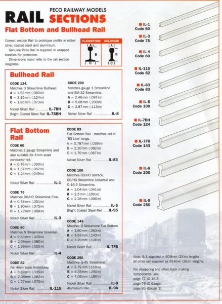
C&L may have slightly different values for the web.
If you want a bigger copy of the above - e-mail me at mabocat@adam.com.au
Ron
NCE DCC ; 00 scale UK outline.
NCE DCC ; 00 scale UK outline.
Posted

Full Member
Street tramways typically have the rails embedded in the road surface itself, set in concrete, bitumen or stone or wooden setts / blocks. Some street sections have reserved track where the full height of the rail is exposed.
To represent urban tramways with rails set in the road surface you need nothing more fancy than code 75 rail and can get away with code 100 if you must. The former is closer to actual rail dimensions scaled down and looks better.
If you wish to represent reserved track with the whole rail above ground then code 75 will again do the job although specialist tram rails would be a better, but likely expensive, option. Bullhead rail, not flat-bottom, should be used for all but very recent track though if only the rail head is showing the bottom doesn't matter.
Street tramway rail sometimes contains a groove inside the running rail face to prevent tram wheels from grinding down the road surface. In cross-section this looks like an inverted letter h and is sometimes referred to as "grooved tram rail" or "h-section rail". Normal rails which resemble a serifed capital I in section are simply called I-section rails by tramways to distinguish them. Modelling h-section requires specialist rail or very skilful application of a rail-coloured skin or film to the outside of the groove. I have seen it done and very effective it is but I'm not sure how it was done.
Perhaps take a look at Peco's "Individulay" branded range of components where code 60 rails might be an option for you.
 Last edit: by Gwiwer
Posted

Full Member
I have seen Code 75 railway track with a Code 55 rail soldered against the inner face to represent the grooved rail Rick speaks of but in all honesty, it's not really necessary because you can't really see it at normal viewing distance. Use plaster to infill the road surface between the rails and just before it sets hard, "cut" the groove by running an old, coarse wheeled wagon along the track then clean up the groove it has cut. Either carve or score the setts into the almost dry plaster - easier than using plasticard infill. Using a "press" to emboss the setts can be done but you have to be pretty quick before the plaster goes off. Adding some PVA to the plaster mix tends to toughen it up and allows some slight "flexibility" which helps prevent cracking as it dries.
Points can be either small radius Peco type or, better still, hand made so again, you can get tighter radius curves.
Grooved track was used when laid in a road surface but for reserved tram track, ordinary rail was normally used. As Rick again said, the rail section was considerably smaller than train rail because trams were much lighter.
"Electric Avenue" and "Swedtram" both manufacture very good extruded grooved rail but the former really needs their "Proto 87" finescale wheels to make best use of it and the latter (originally made as "Orr" track in the US, but now manufactured in Sweden) is very expensive.
Electric Avenue is here : http://proto87.co.uk/electric-avenue-tram-streetcar-track.shtml
Swedtram is here: http://www.swedtram.se/eng/swedtrack/swedtrack.html
'Petermac
Posted
Full Member
This forum is Biblical, "Seek and ye shall find, ask and it shall be given".
 thumbs
There is enough information here to let me design my pointwork so that it will fit on to Peco code 75.
To be honest I am looking at using the rail without the sleepers and soldering direct to PCB board copper faced strips or the heads of nails knocked into the baseboard.
As far as the groove goes in the case of modelling its major use is to prevent plaster from the road surface getting into the inner surface of the web of the rail.
I intend to use printed cobbles and glue them down but I might try to make up a roller to impress them. I will certainly try to make a stamp to impress manholes and stanks which will be far better than printing them and gluing them down.
Once again thanks Guys.
Jim
Because, except in some unfortunate circumstances, trains did not run on town centre streets
Posted
Full Member
If you do make your own track with PCB sleepers, make sure there's enough depth in any plaster infill to give some strength. PCB sleepers aren't very thick and thin plaster cracks easily ……:roll::roll: Also, don't forget to gap the sleepers, particularly around the point area where it's easy to miss the odd gap thereby creating a short.
Using printed stone setts glued in place is easy on straight track but becomes quite problematic on curves and points. The printed setts are "square" to the print but on curves and points, they should follow the rails so would need some method of curving them. You could use, and I have seen, plasticard inlays again with the setts scribed on. It's boring, slow and labour intensive but the result is superb. If it were me, I'd use plaster and hand scribe it. Once set, provided your "groove" is wide enough to clear the truck wheels, there's very little risk of the edge crumbling and fouling the rails. That's why it's best to use the old coarse flanged wheels to cut the initial groove in the unset plaster.
Another method, which doesn't really appeal to me, is to lay a piece of string along the inside of the rail as you lay the plaster. When it's "green" (the plaster), you carefull peel the string out and it leaves a gap between rail and plaster. When it's finally set hard, a quick tidy up with a scraper cleans the rough edge and away you go with your paints ……..:thumbs
Good luck with it - it makes normal model railway "ballasting" look like fun ………………:cheers
'Petermac
Posted
Full Member
All good advice and it will be heeded. However as I will be using overhead positive and twin rail return I only need to use isolating frogs on the return and I eliminate the need for insulated points etc as the entire system becomes basically a single length of track with the direction of travel dictated by the wiring up to the tram motor. In other words when I put the tram on the track the motor will start up and go in one direction only depending on how I wired the feed to the motor. The tram will always go "forward" unless I put it on the track back to front. The isolating frogs will allow me to create section in the track and automatic start stop sections or different speed sections. You need to think long the lines of turning your trackwork on its side and you can see that all the complex insulation etc used if a loop is put on a single track simply no longer exists.
As far as cobble surfaces go I can use printed cobbles if I use This:-
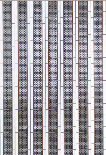
Cut into strips these cobbles fit between the rails and if you cut them on the lines shown they will bend without creasing. You need to do a test run first and put small slivers of cobbles where the gap widens but where it narrows up it does not matter.
These are John Wiffens Scalescenes cobbles so please don't pinch them. I'll send you an overlay if you want to use the method.The Brown edge is where the inner part of the rail groove is.
Also, on the dock section that I have already built I found that using several layers of card I can build up to rail height alongside the rails and slope down to the gutter to simulate the crown of the roadway. I still have half of the dock to surface so I'll get some pics as I go on with it.
Regards
Jim
Because, except in some unfortunate circumstances, trains did not run on town centre streets
Posted
Full Member
This is what I mean for curves. The curved cards are to drop on to the baseboard while I am figuring out where things go and are the tightest (150 mm radius to inner rail) that will be on the layout. Anything tighter will be tarmacked and wont have trams on it because it's too tight.
You can see the white sections on the outer edge of the curve and when the glue, glue stick in this case, dries I will colour it in with some grey felt tip.
PVA would be better but I did this in a hurry.
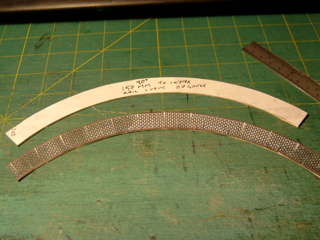
Yes I will make some specific 150 mm radius inner & outer curves but this is intended to be used on "wiggles" in the track and nowhere near as tight as this.
Regards
Jim
Because, except in some unfortunate circumstances, trains did not run on town centre streets
1 guest and 0 members have just viewed this.