How to wire points
Posted
#249875
(In Topic #13757)

Full Member
Need some help from the experts
Hi all,I have bought two used points for Wombat Creek Tramways for a very good price. Until now all my points have been with insulfrogs, but these ones are electrofrogs (I think). They may come from a DCC lay-out, but I am building DC (analog).
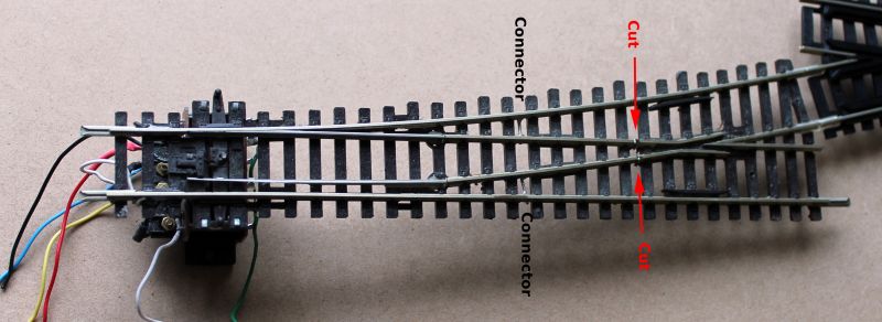
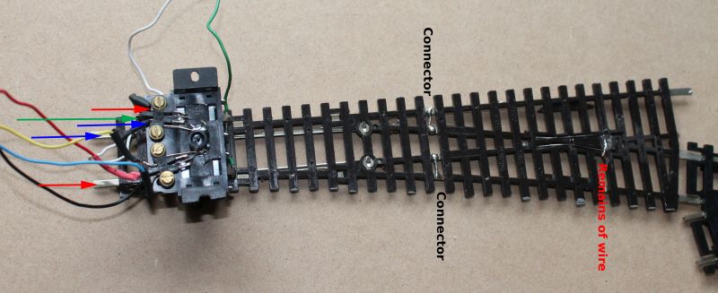
How do I do the wiring? The photos show the upside and downside of the points. The green, white and black wires are for the solenoid. I don't know the purpose of the blue, red and yellow wires. There is a connection between the two red arrows and the two blue arrows and room for wire at the green arrow. I guess a wire should go from under the frog to somewhere at the back, but where?
Please, can I have some help!
Cheers,
Claus
www.flickr.com/photos/ellef/
Claus
www.flickr.com/photos/ellef/

Posted
Full Member
I don't know exactly how the switches are connected (I don't have any of these) but the connections would be to select which rails are connected to the frog to keep it "live". You will have to insulate the other side of the frog for this as well on both rails.
Effectively you should have three wires the central one of which should go to the frog while the other two go to their respective side rails, possibly just connecting to either the feed wires for that block or connected to the adjoining rails. Depending on which way the motor is thrown will also set the electrical path. The central wire (and I am prepared to be corrected on this) whould go to where you have the remnant of the wire underneath the frog.
A diagram to follow if you need it! I am expecting a few phone calls today so it might be a little while in coming.
Cheers
Trevor
Posted
Full Member
Hello Trevor,Thank you for your reply!Hello Claus,
I don't know exactly how the switches are connected (I don't have any of these) but the connections would be to select which rails are connected to the frog to keep it "live". You will have to insulate the other side of the frog for this as well on both rails.
Effectively you should have three wires the central one of which should go to the frog while the other two go to their respective side rails, possibly just connecting to either the feed wires for that block or connected to the adjoining rails. Depending on which way the motor is thrown will also set the electrical path. The central wire (and I am prepared to be corrected on this) whould go to where you have the remnant of the wire underneath the frog.
A diagram to follow if you need it! I am expecting a few phone calls today so it might be a little while in coming.
Cheers
Trevor
I think you are right. I will do a 'test run' and let you know!
Cheers,
Claus
www.flickr.com/photos/ellef/
Claus
www.flickr.com/photos/ellef/
Posted
Full Member
 th
thClaus, I found this diagram showing effectively what you have but the arrangement seems different for the switch. You will need to check the switch positions with a multimeter on what you have to equate it with this diagram,
Hope this helps
Regards
Trevor
Posted
Full Member
I will give it a go!
Cheers,
Claus
www.flickr.com/photos/ellef/
Claus
www.flickr.com/photos/ellef/
Posted
Full Member
Cheers Pete.
Posted
Full Member
My next problem is an Atlas crossing. The 'groove' on the inside of the rails is not deep enough (I think) for a couple of my old locomotives, which the Tramways use for maintenance work! If I can't cut it deeper, I am afraid the crossing will be on its way to the bin!
Cheers,
Claus
www.flickr.com/photos/ellef/
Claus
www.flickr.com/photos/ellef/
Posted

Full Member
As far as I'm aware, it's not really practical to cut deeper grooves in the track base although in theory, it should be possible …………………
Let us know how you get on ………
'Petermac
Posted
Full Member
Not that I have "deepened" an Atlas crossing but would it be reasonable to ask what the model is that you are trying to get through it? The older Hornby and Triang based locos will have an issue because of deeper flanges and Triang based locos were notoriously under gauge which is fairly easy to correct.
Atlas products are not as consistently engineered as Peco ones - have a look at the frogs of left and right hand points sometime and there can be a very notable difference in the flangeways of them. I have no experience of the 90 degree crossing except that the frogs may not allow contact to be maintained on shorter wheelbased locos. Are we talking Code 100 or smaller?
I have just looked at an illustration and wonder if the plastic "square" in the centre of the crossing can be shaved a bit thinner? If you have an NMRA gauge, check your wheelsets and the clearances of that crossing and treat it accordingly.
Hope this helps
Cheers from Ocean Grove
Trevor
Posted
Full Member
Cheers Pete.
Posted
Full Member
Thank you very much for all your comments and suggestions.
The four 90 degree crossings are fine. The problem is a 19 degree crossing a little further along the line. It is a code 100 so the problem lies in the construction. I will have another go at it later today. I must finish teaching from home first.
 Last edit: by Claus Ellef
Cheers,
Claus
www.flickr.com/photos/ellef/
Claus
www.flickr.com/photos/ellef/
Posted
Full Member
Check the lead in to the crossing, perhaps even using it loose and testing locos going across it on the bench rather than on the layout to see where the issue might be with the wheels. With the 19 degrees, I wonder if there is a side movement perhaps hitting the guard rail causing lift before it gets to the frogs.
You have mentioned "old locos" which I presume means you have got some chassis that you have modified - it might help to know what those are as someone here should have a bit of experience with the same or similar chassis/base loco etc. Otherwise would a Peco short crossing not fit instead with extra approach rails?
We might be in a can of worms with this one… keep in touch!
Cheers
Trevor
Posted
Full Member

The photo shows 'the weapon of choice'. With this rather brutal saw I have cut along the rails and managed to lower the grooves to 1.5 mm. The little vintage (over 40 years old) Kleinbahn diesel runs through the crossing without any problems even at low speed. I will return to my main entry Wombat Cree Tramways and report further progess with the extension.
Cheers,
Claus
www.flickr.com/photos/ellef/
Claus
www.flickr.com/photos/ellef/
Posted
Full Member

'Petermac
Posted

Full Member
Many diamonds have conducting metal strips buried in the plastic to power the inside rails.
Nigel
©Nigel C. Phillips
Posted
Full Member
Well Done and an admirable solution with basic tools. As Nigel pointed out, you could cut into conductive strips going too deep as well as upset the holding of the rails by the plastic moulding so care is needed but it would seem that you have exercised that well.
When you come to lay that crossing in its final place, just be careful that it does sits as flat as it would on the bench. I have one Peco short crossing that has a tendency to bow very slightly upwards and cut contact even with an 8 wheel loco travelling over it. The main issue is most likely the different expansion and contraction rates of the plastic base and the rails and in my case the extremes of weather to which the layout has been subjected. My layout was in a shed when we lived nearer Melbourne. The full range of temperatures it would have experienced would have been in the -1 or -2C through to about 45C (and warmer on one or two days).
I take it your layout is inside as mine is now so the extremes will not happen in my case again but there will be movement. Part of living here in Australia I suppose!
Cheers
Trevor
Last edit: by xdford
Posted
Full Member
 [user=6]Petermac[/user] wrote:
Carefully machining thin slivers of plastic with fine precision tools usually sorts out most minor faults Claus ………………………………….
Cheers Pete.
Posted
Full Member
I started out with a less 'brutal' tool, but it took too long. So out came the saw. I was very careful not to go too deep and took several measurements. The advantage with the saw is, the blade has the right thickness for the required groove.
The tramways are inside the house and I make sure to draw the curtains during the warmer/hotter days. I hope I will not the any expansion issues. One issue I do have is, Atlas' sleepers are thinner than Peco's. 2 sheets of 300 g paper to be exact. Easily solved, though.
Cheers,
Claus
www.flickr.com/photos/ellef/
Claus
www.flickr.com/photos/ellef/
Posted
Full Member
The rail profile is slightly different as well. Which usually means fettling the joiners.
Nigel
©Nigel C. Phillips
1 guest and 0 members have just viewed this.