Processor Control of Lineside Items
Posted

Full Member
How to automate and control signals, level crossing gates, etc.
Thank you guys for your continued interest in this section on automatic signalling. Perhaps a little background might be appropriate; a little insight into it all.I have every admiration for those that pulled the levers in the signal boxes up and down the country that kept our railways running safely. But I also have admiration for those who developed the interlocking systems that go on under the floorboards. This system must surely be at the heart of safety and helped prevent errors by said signalmen pulling the levers.
The idea behind this project kinda follows along the lines from the Hot Chocolate song "it started with a kiss, never thought it would come to this" whereby it developed from a simple idea and it just went on and developed into what it is today. So yes, it started as an idea, then I started to look around as to the "how to", hardware-wise. Arduino boards or the PICAXE processors. Then the software. Programming…. The C+ language or BASIC. I've been playing with programming on and off since the days of the first Sinclair Spectrum (that shows my age! - but only with the BASIC language and dabbled with VB6) and I've always been involved with electronics repair - from the early radio sets (with valves - you know, the very old glass devices that glowed and got very hot) through TVs and into computers. The magic and thrill of repairing stuff has all gone these days as about the only thing you can do is board swap. That's not me; I like to get down to the faulty component.
And the joy of software programming is that it's possible to replicate the hardware inter-locking systems of the old manual signal boxes, only in software. And, I guess, in many ways it's very similar to the new, modern signal boxes that control huge areas of the rail network - only these are much, much bigger and more complex.
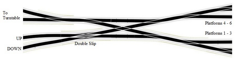
I started with the Home (approach) signal controlling entry to the Terminus. In the case of my John Street layout there is a double slip at the entry pinch point so that depending on the setting of that first point a train would only have access to or from either the UP or the DOWN line (no reverse running allowed here). So it was a simple check to see the setting of that single point. If it was set for the UP (incoming) line, then go and check other points settings to see which platform is accessible, set a green aspect and display the platform number on the display.
At this point I've not incorporated a platform occupancy test (no sensors in place). But maybe there is a power-fail memory location I might be able to access and write to that area which could hold such data (without having to use sensors). Something to think about in the future.
That first part of the project worked well so I thought about trains departing the Terminus. Check the points settings and if a correct exit path to the Down line is set that corresponds to a particular platform starter button being pressed then set a corresponding green aspect.
There's a sensor buried in the track under the double slip such that a green aspect from either signal will reset that signal back to red following a train passing over it. For incoming trains particularly it also resets the occupancy of the incoming section. It's all in what can be done with the programming.
And so it went on - adding bits as it progressed; that's why it's taken so bloomin' long! The main problem was controlling the access to the sidings from the same processor. Just not enough i/o ports when each of the points needed monitoring as well as having all the signals coming from it. So I needed to find a way around this.
The built-in inter-chip communication system (i2c) was found. By using this I could share the points settings monitored by the Home signal and have them copied over to the Terminus processor. And then there was the methodology of having logic to provide a green aspect from just a red output, as noted above; anything to save on the number of i/o ports needed.
Then it was just another development to adding a third processor to control the layout signals. This also had a need to monitor the level crossing gates as to whether they were open or closed to train traffic. And again using logic to provide yellow aspects from just red and green outputs. Anything to save more processor ports.
So it's just like a building block game, adding sections and improvements as the situation demanded. Work still to do will be to add the positioning signals on each platform exit and to build up the rest of the Track Diagram (1 board out of 4 done) as well as finishing off a couple of sensors around the layout. So it's still work in progress with only time being the limiting factor to finally completing it.
Hopefully this has given a bit more of an idea of how it started and progressed to where it is today. But I'm sure more will be added to this project as time goes by - such as the platform occupancy idea.
Next up, I think, will be the turntable if I can find a way to retro-fit to what is already in place and given the awkward location of it. Looking at ideas already! Watch this space (but don't hold your breath).

Posted

Full Member
Staying on the thread Kevin.
Posted
Full Member
I think these servos are used in model aircraft - the SG90 servo (below) - the horns being the plastic arms that screw onto the servo spindle. Why they're called "horns" beats me, I thought it was only bulls and various other animals that had "horns". :hmm It's a whole new vocabulary some of this stuff!
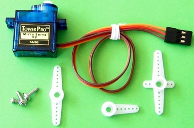
I'm sure you could use some form of wire linkage from opposite ends of one of the double-ended horn arms to simultaneously throw a pair of points, similar to the method I used for the level crossing gates as in my post #1 on 7 Aug 2020 - not the first attempt to direct drive the gates, as in post #10. Substitute the single arm for the double arm, and a couple of lengths of stiff wire to drive the point mechanisms. Personally, I've not used servos to switch points, but I've known it done.
Good luck with it.
Posted

Full Member
They worked very well, were virtually silent but I did find them a bit fiddly to set up. I will be using them again on parts of Maxmill Mk 2.
Your latest posts are starting to make a little more sense to me Dave. :thumbs As with most things, when one breaks it down into manageable chunks, the clouds usually thin a little. Trying to look at the whole project was certainly overloading my few remaining brain cells …………………
I'm still totally in the dark about what goes on inside those little black boxes but, as long as they dod what they're supposed to do, it is of little importance how they actually do it…………… Half the skill is surely in knowing which black box does what !!
I also think maybe, just maybe, by reading your posts and trying to get my head around what's going on, instead of simply shutting down, pennines are starting to drop - very small pennines maybe but at least they're dropping !!!
A year or so ago I would never have believed I'd ever have any interest whatsoever in electronics, beyond knowing what the end result is. Now there's a spark so headway is being made and I thank you for that ………………….. I think …………………….!!

'Petermac
Posted
Full Member
Staying on the thread Kevin.
Posted
Full Member
As for the couplings, I've looked at the Kadee devices and it seems an awful lot of messing about, especially if a lot of the rolling stock is not "modern", shall we say. I've a right mix of couplings, some NEM, most not. Some link up easily, some don't (different heights, etc.).
One day…..
And Peter
Like you, I don't quite understand these little black boxes as you call them. All I know is if you prod them in the right manner, they'll (hopefully) do something constructive, otherwise they'll do nothing and they give you no clue as to why.
It's all about learning - and I've been doing quite a lot of that lately with this project - and I'm still doing some more learning even now (see the next post).
Posted
Full Member
I'm specifically talking here about the logic 7404 INVertor chip that I need to use to effectively change the polarity of the supply for the LEDs on two 2-aspect signals that were wired up conventionally, and not like the remainder of the LEDs which are fed from a permanent +12v with the LED cathodes being switched to ground via the ULN2003a drivers to turn them on.
Looking at the specification sheet for the 7404 it shows a sink current of 16mA - that is power that the chip will accept at its output pin to pass to ground, sufficient to light an LED, i.e. +12v > LED > limiting resistor > 7404 plus PIC output > ground. And this is fully acceptable for my needs for these two signals. It works.
The way I have currently wired the circuit board is PIC output > 7404 > 2303a > LED > limiting resistor > +12v. And it won't work! Well, it does but the two aspects are on at the same time - NOT ideal (or wanted). Connect the LED to ground rather than +12v and it fails to light.
The answer? Remove the 2003a (which re-inverts the logic signal - already inverted by the 7404) and connect the PIC output > 7404 > LED, remembering to change the limiting resistors from the standard 1k (for the +12v) to something like 300R (for a +5v from the 7404) > ground. Now it works again.
These breadboard devices are very useful for prototyping and trying things out and is something I should have played with before committing the pcb. Their only problem, I find, is that the components don't always connect 100% to the holes in the board and things can be a little intermittent if any of the jumper wires/components are touched.
And there has always been a bit of confusion in my mind with a lack of complete understanding of the links between the terms IOL, IOH, sink current and source current, high state and low state.
For the sake of clarity for those who may be as confused as I was (maybe still am):
IOL is the Low state, i.e. logic "0" (or 0v), and it's the amount of current the pin can accept (sink) to pass to ground (or another chip). In logic chips terms, IOL is around 16mA.
IOH is the High state, i.e. a logic "1" (or +5v), and it's the amount of current the pin can pass (source) FROM the chip. In logic chip terms, IOH is around -0.4mA. And the minus figure confuses me even further. It seems it's because the current is effectively flowing the wrong way. Positive figure = into the chip, negative figure = out of the chip, i.e. it doesn't/shouldn't. Not if you want or need to keep the logic value of "1" at that pin. Any figure above 0.4mA being sourced here and the voltage at that pin will drop from it's logic "1" value. But it is quite possible to drive the base of a transistor or FET by this pin or to drive an LED with a small amount of current; to much current and the LED fails to light due to the drop in the voltage from the pin.
I think I've got that right even if it still might not make a lot of sense! If you weren't confused before, I'm sure you will be now - so apologies for that! I've not really used much in the way of "logic" devices until now; mostly I messed with "analogue" signals, not digital. That's my excuse!
But if anything, I think I do understand it more now I've given it a bit of a write-up. Give it a minute or two and I'll not be quite so certain once the grey cell has had a lie down!
If I have any more thoughts - or it there are any questions - I'll come back to it.
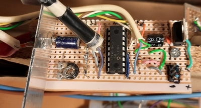
I'll add a photo of the breadboard and the circuits used for parts of the signalling in the next post.
 Last edit: by Dave C
Posted
Full Member

In the breadboard photo, the chips are,left to right, ULN2003a, 7404 INVertor, 7402 NOR gate with pin numbering on each chip from bottom left being pin #1. The output from the PICAXE is simulated by jumpering a couple of wires to either +5v or 0v.
On the ULN2003a the inputs (being simulated from the PICAXE) are applied to pins 1 (green) and 5 (red). The outputs are taken from pins 16 and 12 respectively. These then go via their 330R resistors and the LEDs to the permanent +5v supply (+12v and 1k resistors when on the board proper). The ULN2003a ground point is the blue wire on pin 8. The 2 logic chips have +5v on pin 14 and ground on pin 7.
For a (missing) yellow aspect: The yellow signal is derived from the two simulated PICAXE outputs (R&G wires) and taken to the input pins of the 7402 (pins 2 & 3). The output from pin 1 (yellow wire) then goes to the ULN2003a pin 7 with the output on 10 which then goes via its 330R resistor and LED to the +5v supply. In this manner, there is a yellow aspect lit if and only if both the red and green aspects are off. That is using the less-than-conventional wiring with each LED connected permanently to the positive supply line and the ground being effectively switched by the ULN2003a. Two output pins, three signal aspects. See the diagram below.
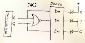
To power the two "conventionally wired" signals the output from the PICAXE red output is sent also to the 7404 INVertor chip on its pin 1. The inverted output is taken from pin 2 to the 330R resistor and the green LED (far right) to ground. The red aspect is taken direct from the same PICAXE output via the 330R and LED to ground (now on the breadboard). One output pin, two signal aspects: Red on, Green off, and vice versa.
Total current from the PICAXE across all signals is around 100mA and well within its specification when driving most signals via the ULN2003a driver chip(s).
That might help explain how this lot is actually wired when it gets to the layout. So a minor change to the pcb is required and then it'll be power-up time.
Hopefully, this might give a little background into wiring signals from logic or microprocessor circuits, always being aware of the current capability of each output port and of the device's overall total current capability.
Posted
Full Member
Posted
Full Member
The various sensors have been mostly installed (and modified where required so that the in-track sensors do not "see" inter-truck coupling gaps). I'm in the process of having to re-do one sensor board due to a wiring mishap. The sensors still missing (different sensor board) are in the shunting areas - these can always be added later - I'm wanting to get the main layout completed, that has been the primary concern up to press.
The signals have all been checked, and after a short panic due the wrong LEDs lighting up caused by one plug being shifted left by one pin, all now looks to be good. The reverse wiring requirement of a couple of signals has been sorted - most signals use a common +5v (switched return connection) while these two use a common ground (switched +5v as normal). There's nothing like standardisation - or forward planning! And the points have also been wired in to the main circuit board and checked. Likewise the platform starter buttons have also been checked.
The track diagram boards are still work in progress; board one has been done; 3 to finish.
Also still to be done: the Home signal module needs a couple of wires moved about due to the communications ports now being needed that currently hold other functions connected to them - and an updated program to be installed. And there's more…
The level crossing needs to be checked to ensure that the gates open/close to the correct positions and the open/closed signals are being set correctly for the next processor in line.
Soon it will be time to insert the processors and then we'll see how it performs for real. And then…. If only I could keep focussed on one job at a time.
Thoughts have been had regarding the next project - modifying the turntable - it currently doesn't always align correctly to the exit tracks. And it's too far away from the operating position to tweak manually. At this point I'm looking at using a small stepper motor and (you might have guessed) a PICAXE to control it.
There is quite a lot of experimentation to be gone through before I commit to anything. Thoughts are to use the 28BYJ-48 stepper motor - very small with a reasonable strength behind it, more so once it has been modified from its unipolar style to bipolar. These motors are very cheap from the far east (delivered in unipolar mode) but to use bipolar mode it needs a different board/driver chip to operate it from the ULN2003a driver usually supplied - it will require a L295D H-bridge chip. I do still need to find a method of setting an index position from which everything else will be calculated.
My problem is the turntable is installed into the baseboard and everything fixed up to it - but then after a while it was noted that it didn't really align too well. So whatever needs to be done needs to be carried out in situ - and with very little room between the well underneath and the tracks that run under it, it ain't gonna be easy. I can foretell the air is likely to become a little blue!
Posted
Full Member
Staying on the thread Kevin.
Posted
Full Member
As far as manual control is concerned, the turntable is way over the other side of the layout and some of the exit roads I can't see clearly enough (totally wrong angle of viewpoint) to align the TT to the tracks. So whatever I do, it's got to be some form of automatic indexation.
But thanks for the thought.
Edit:
Back after a few jobs done - and a quick look at the DOGA turntable idea. Talk about simple! Effective though. Shame there's no photos visible, no doubt lost in the sands of time given that it goes back to 2003. But good line of sight is needed for anything manual such as this. And that is, as I mentioned above, is my big problem. Side-on sight of an exit road and, given my ageing eyesight, even the mostly straight-on track alignment would be a problem. So I have no option but to go with some form of automatic alignment - and I always like (prefer) the DIY approach. I always get so much satisfaction from designing/building something myself. So back to the drawing board.
But appreciate the pointer - that idea "could" possibly come in handy for some other project yet to be thought about.
Last edit: by Dave C
Posted
Full Member
Staying on the thread Kevin.
Posted
Full Member
Sounds like a completely separate forum…Are you a member of DOGA?
Posted
Full Member
Staying on the thread Kevin.
Posted
Full Member
My recently bought solder reel, which I had bought in good time, appears to be pretty useless when it comes to using it. It seems to heat when trying to solder into something like paste and not flow like it should, not like my old reel of solder. Both were 60/40 fluxed solders. Maybe some additional, separate flux might help. Anyway, so while I'm waiting for the new stuff to arrive - hoping this stuff is going to be better - I thought I'd add a bit of a write-up on adding/renewing indexation to my turntable.
So the following is more regarding methods of getting indexation to a turntable rather than how to implement it being automatically controlled by DCC. I have no knowledge of how to implement DCC to operate such a unit, but no doubt there are ready made kits out there that will do the job.
Indexation. A bit of background on the indexing options, each has it's own for's and against's:
Mechanical - using microswitches;
Electromagnetic - using Hall effect switches - oh, and a magnet (what else?);
Optical - using infra-red LEDs.
Mechanical: probably not the easiest to install or setup and switches can (are) "noisy" devices, i.e. (a) they don't always switch at the same point, and (b) at the point of changeover the contact can "bounce" giving unpredictable results. A "clean, repeatable " changeover is absolutely desirable. Hence, the following options.
Electromagnetic: easy to install with no power requirements (on the turntable deck). Although I've yet to have a try with this, I can foresee a problem or two - mostly the activation point of the Hall effect sensor and this can depend of how strong the magnet is and how far away the Hall effect sensor is from the magnet.
One problem here is that the sensor is likely to trigger at differing points depending on the direction of deck rotation, giving rise to an alignment error. But having said that, this is/might be my option of choice.
Optical: easy enough to set up despite the need to find a source of power for the Infra-red emitter.
The source of power could be taken from the supply to the rails but only if running DCC - with DC running, this doesn't work. But with the turntable in situ and not easily removable, this might not be quite so easy.
Again, I have yet to have a good look at this but I think that a small diameter hole could be drilled into the well or the side of the turntable and the sensor receiver made to align with what should be a very narrow beam coming from the emitter.
Another optical option is to use a slotted disk through which to shine an Infra-red beam using an optical interrupter as used by Locomotech and currently fitted on my turntable but which, unfortunately, tends to lack accurate alignment depending on whether the deck is rotating clockwise or anti-clockwise. I'm not rubbishing the kit - it just didn't work for me. Other than the indexation disk, it worked perfectly and quietly - but I'm not in an operating position to physically see the alignment to some tracks for which it needs a tweak of adjustment to prevent derailments.
Hence I'm now looking at a retro-fit of another method of alignment and the change from the current DC motor to a stepper motor.
If you choose to use the Hall effect switches (with a magnet), beware there are two types of switch available: analogue and digital.
The analogue type produces an output that is dependent upon the strength of the magnetic field, i.e. the output varies. It's then up to the designer of the electronics to decide, with the aid of a voltage comparator, at what value of magnetic field strength to make the switching point. The digital type, on the other hand, has a fixed switching point using the internal Schmitt trigger. A commonly used type being the A3144E. Once the Hall effect switch makes the switch between states, it's a simple matter to count the number of steps to make the turntable align with one of the tracks - all other turntable stopping points (tracks) can be counted from that one initial point.
At this point I am tending to try the Hall effect switch&magnet with the optical Ir method (using a small hole in the turntable well) as a backup option. I've no idea how either will work and I need to try things out using something other than the installed (non removable without a lot of hassle!) turntable. With either method, it's all about counting the steps between each exit road and the initial power-up point. Work on this may move along somewhat slowly (as does most things in the Train Room).
Essentially, for the motor using any of these indexing methods, you would need to make use of a stepper motor. A bit of technical info next, but info that is needed for the correct operation of the turntable.
Looking at the 28-BYJ48 (sometimes known as BYJ48-28) small stepper motor it takes 4075.77 steps to make the 360 degree deck rotation using the internal 64:1 gear train. That is, using half-step mode; with a quoted 5.625 degrees per step of the motor and with 64 steps per one revolution of the motor shaft (gear ratio being 64:1 - or 63.683951:1 to be more accurate). Even these figures vary slightly depending of whose information is read. I get the impression there have been different gear trains used in these motors, one that gives near 4076 steps and another that gives 4096. So either figure would indicates a step size of about 0.088 degrees per step of the motor - I think that's accurate enough for most alignment purposes.
Most of this write-up is a bit of future thinking and is certainly becoming work in progress (when I find the time). I've written a small program to test the number of steps per 360 degrees and I've been building a jig to run it before I dismantle the turntable. In the meantime, it's back to the signals (again) once the solder arrives.
Posted
Full Member
I've been working on a program to operate a stepper motor. All track locations are setup the first time the program is run - the magnet is first located by moving the deck anti-clockwise; it then waits for a move clockwise to the "home" (main track) position and then to each of the other exit roads and each stop position is "saved" to the processor eeprom. The turntable then moves under its own power to the first exit road and waits for a manual move anti-clockwise back to the "home" position, this is again saved to eeprom. From the two "home" positions the amount of backlash of the motor/gearbox is calculated and this is also saved to eeprom. That's it for the setup. In normal runtime mode the number of steps is calculated from the current initial "home" position with an allowance for the backlash to the next desired position depending on whether this move is clockwise or not and whatever direction the last move was (CW or CCW).
That's the theory - the program seems to work in simulation mode. All I need now is some time in the Train Room to see if it works out on a jig - i.e. the motor with a spindle rammed into a piece of wood (turntable sized) and a fixed piece of card to mark where each track could be - and then to see if it does actually align correctly each time, whether it be turned clock- or anti-clockwise.
To minimize any backlash in the gears, a planetary type of gearbox can be used instead of the more normal - and far cheaper - ordinary type of gear wheels on shafts. But that puts the price of the entire motor at a premium (they seem to come as a pair). Whether the slack of an ordinary gearbox is something that can be worked around will be dependant upon the motor/gearbox combination. I may be about to find what the slack is in the cheapo BYJ motor. I hear it's not brilliant. What can you expect from a motor that is less than the price of a pint?
If the BYJ stepper isn't up to the job, the next stage would probably be to source a motor of more suitable strength - there appears to be very little made or stocked within the UK that gives the resolution of the small BYJ stepper. But the price! By the time the import duties, etc. are added, anyone would think I was wanting to buy the company! Maybe that's a failing on my part of living with the prices of the past.
Be interesting to see how it works - with the BYJ stepper firstly. I've checked the operation of the Hall effect switch and with the small 4mm dia. round magnet I have, the switch senses it from about 6mm away from the magnet's south pole (the north pole does nothing!). So that gives me something to look at when mounting the magnet on the deck (the switch will need to be hard up against the turntable well).
Once this jig is complete and tested, things should move along quite quickly to finding a method of mounting it under the turntable deck. More reports to follow when I progress things further. And maybe I'll get a video put onto YouTube of it in action.
One day I'll finish the signalling! I must get back to it sooner or later. It's been dragging on and on but I've re-constructed one sensor board. I had tried to modify what I had so that I could implement a sensor release delay so that inter-truck couplings would not be seen. Not a success, so a fresh start was made. It simply involves an additional resistor, a capacitor and a diode per input. The delay (hopefully) being about half a second.
Posted
Full Member
The latest is that the turntable is in and working with a new stepper motor (NEMA17) plus a Sparkfun Easy Driver board and the PICAXE processor as the controlling unit. The final stages of programming the processor are in process - a tweak here, a tweak there then see what other parts of the routines have been upset as a result of these tweaks - then start tweaking again!
Not far off now. Full details will be forthcoming on this on my John Street layout page, the turntable saga starting at (http://yourmodelrailway.net/view_topic.php?id=14501&forum_id=21&page=7) from my first attempt using the small 28BYJ-48 stepper motor and ULN2003a driver right through to where I am now - currently on page 9 (and soon beyond).
More updates as and when - but we're starting to get into the caravanning season (once the weather improves) and that means more away time and less train time. Such is life!
Last edit: by Dave C
Posted
Full Member
Posted
Full Member
The 28BYJ-48 stepper motor was scrapped due to the gearing and the amount of unreliable backlash found - I couldn't program the backlash into the software; it was too variable. Therefore a stepper motor was used instead - a NEMA 17 12v 400mA per winding. In order to use this motor without the need for a lot of fiddly programming, I made use of the Sparkfun Easy Driver board - this uses the Allegro A3967 chip and allows the motor to be run simply by having two signals from the processor board (PICAXE 18M2+), the DIRection signal and the STEP signal which will move the motor one step for each positive-going pulse. The ED board allows the stepper motor to work at a maximum stepping rate of 1/8 stepping, thus giving 1600 steps per revolution. The motor tends to be a little bit noisy in use; whether this is the motor style itself or the method of fixing it on a relatively thin piece of board that might be amplifying the noise. To make things a bit quieter I may purchase the Big Easy Driver board - this uses 1/16 stepping with 3200 steps per revolution.

Method of mounting the stepper motor - the Hall effect sensor can be seen against the turntable wall (with the blue output wire).
PICAXE board with the 18M2+ microprocessor and the small motor speed adjustment preset resistor.
All movements are based on an initial power-up search for a Hall effect sensor which is placed against the turntable well outside wall about 10deg. counter-clockwise from the main track; it's also used for any re-alignment during run-time in case some drift occurs during running. The switch has a maximum of about 6mm separation using this magnet before it fails to be "seen" and fails to change state. The magnet was fitted under the turntable deck as far forward as possible without it catching on the well brick paper cover. This is fitted in a very similar method as seen on the Nov 2013 RMWeb page: https://www.rmweb.co.uk/community/index.php?/topic/78578-dcc-controlled-peco-turntable-project-using-a-arduino-uno/ except my magnet is glued onto a small piece of high density foam rammed into the same space under the deck, between the two main beams. Other than the magnet mounting location, nothing is the same between the RMWeb article and my construction. But it's never-the-less a useful article to read through.

Method and placing the small magnet under the deck - this is viewed from the underside.
Then came the testing of the program in simulation mode, and after a few tweaks here and there with the aid of some debugging commands, it all worked perfectly. Also written into the software is a short routine for acceleration and deceleration of the deck at the start and end of each move.
My turntable simply has one in/out track plus one exit into a small engine shed. The program can, with a few adjustments, be written/updated to allow for any movement from one track to another, depending on the specific layout, but it would add another layer of complexity regarding selecting the specific track required to turn to. But, as it stands, the turntable works for me and seems it will work acceptably well.
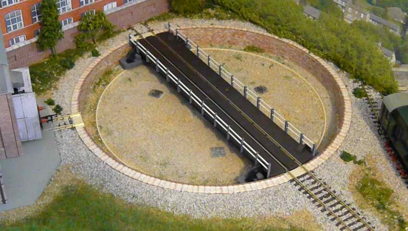
Turntable in situ.
All in all, the components are:
Peco LK-55 turntable;
PICAXE 18M2+ microprocessor;
Sparkfun's Easy Driver board;
A3144E Hall effect switch and a small magnet (5mm dia. x 5mm);
Two 5v regulators (7805) - one for the processor, the other is currently spare/surplus to requirements at the moment;
Decoupling capacitors, 0.1uF and 100uF to keep the supplies steady without spikes or ripples on the voltages;
A few resistors to hold the processor input ports at 0v and one resistor to hold the Hall effect switch to a "high" (+5v) level - the magnet pulls the switch output to a "low" state;
A small pre-set resistor to adjust the rotation speed;
The 4 small push switches on the (setting-up) control box, salvaged from an old printer (CW, CCW, Reset, Save position). And the control box was also re-purposed;
Two push buttons on the mimic panel and a direction changeover switch;
and a 5mm-to-4mm rod coupling;
And that's it - apart from many hours of (BASIC) programming (and simulation tests) to make it work.
The difference between the no-longer-used 28BYJ-48 and the NEMA 17 series of motors is that the former is a unipolar motor (5-wires) while the latter is bipolar (these can have 4, 6 or 8 wires) and each motor style needs a different method of driving them. The unipolar motors are ok with the ULN2003a chip while the bipolar needs an H-bridge arrangement, either directly operated by the processor or via an add-on board as I've used (this takes all the overhead processing from the processor and its program of how far the motor needs to move each time).
For those who like to see a moving turntable, a video has been posted on my YouTube page at: https://youtu.be/RAqhEKJtn5A
Next stop - back to the signalling - after maybe giving the trains a run.
1 guest and 0 members have just viewed this.