Processor Control of Lineside Items
Posted

Full Member
How to automate and control signals, level crossing gates, etc.
Thanks Nigel.On my last layout I did play around with reed magnets and the 555 timer chip but found the reeds to be a little unreliable (maybe it was me and my fumble fingers in mounting them correctly!). Not only that but they only detected where the magnet was, presumably under the belly of the loco (or wherever the magnet got fitted). I'm looking at detecting the entire train. The reeds were also a bit obtrusive and noticeable in that they lay along the track and were somewhat difficult to "hide". But for those that use them, great, as long as it does the job for you.
And to you Chris, again, thanks for the comments.
I did have a look at the Arduino, mostly the Uno, but found that it had a limited number of ports to which you can connect things - am I right in thinking only 20 digital and 8 analog? Maybe there are add-on boards to increase this number of ports but that then adds to the complexity of it. Having said that, I guess my idea of using the PICAXE processors is just as complex in that I only have the bare, naked processor to start with, and it along with everything else has to be mounted onto a piece of board. Swings and roundabouts, I guess. But the PICAXE 40X2 has up to 32 ports for connectivity and even for my needs I have found it limiting when trying to sort the signalling out.
For instance to save ports, I have to generate a three-aspect signal from two outputs and a two-aspect signal from just one output - plus a couple of logic chips to make up for the deficiency and the missing aspects - more on this when I get round to the next instalment, coming (I hope) shortly. Presumably the Arduino is as capable of only driving a limited amount of current from each port (and overall) as the PICAXE. Therefore, if you want to run the layout signals as well as duplicating them on a mimic board then other add-on chips to increase the current capability would also be required.
Don't get me wrong, I'm not trying to put you off the Arduino. In some respects I'm trying to make a comparison about the Arduino of which I know very little about. Like the reed switches/magnets mentioned above, it's horses for courses. You run with whatever you feel is right for yourself.
I'm not sure about making videos…..I only recently found out I have a YouTube channel by way of the GMail account, I think that's how come I got it. Never even thought about videos. Maybe one day. At the moment there's not enough hours in the day to do much on the layout (same old story, I know). Can't recall the last time I actually ran some trains.
Anyway, glad you're enjoying the series, Chris

Posted
Full Member
Well, life over the past few months has certainly been getting in the way of all things railway. But there is progress, slight though it might appear. The circuit board has finally been completed and the inter-connections checked and double and triple checked - it's not been supplied with power yet so there is still a chance I may have missed something along the way. Once I start checking the board it will be very slowly, slowly, bit by bit.
Then I can start to connect up the sensors and signals and the associated layout mimic/track diagram. But even some of the signals and sensors are not yet in place - so there's still a lot to be doing before it all gets up and working.
But to give an indication of where we are, the following is a preliminary shot of the circuit board - on standard stripboard.
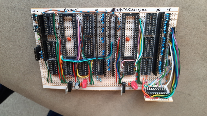
Note the two large processor sockets and small add-on board for the "master" processor - not enough room to squeeze it onto the main board - and the use of two 7805 regulators (just to make life easier on having just one of them). It's still a bit cramped though.
So, as you can see, there IS life at the end of the tunnel - if only someone would turn the light back on! …. more to come in the next few weeks as and when I can get the time together to spend in "The Train Room".
Posted
Full Member
The signals are now installed and connected up to the (new) main patch-panel - there are over 120 individual wires to connect through. The sensors are also getting there. The original sensors in the hidden track area were all initially run from +12v - which is of no use what-so-ever for feeding into a processor that only likes +5v. So they are in the process of being updated and modified for +5v. They all need updating as there will be an overall layout track diagram complete with (pseudo) signals in the hidden section (only visible on the track diagram) and the sensors are needed for controlling them. The signals also need to be wired essentially back-to-front with a permanent +12v to the anode of the LEDs - it's the negative side (the cathode) that gets switched to ground (via the limiting resistors) which lights the light, so to speak.
When I started this layout I didn't really have a long term plan of what I wanted to finally achieve. And processor control of the signalling was far from being in my mind at that time.
If only I had made a plan! How many times has that been said amongst us all? And signalling didn't come into it.
Ah well, that's life I guess. At least I'm trying to keep everything written up and making notes of wire colours and where they start and finish and their purpose in the grand scheme of things. Which is helpful - until you look at the masses of wires strung all over the place under the boards and at the few circuit boards fitted wherever there was space to fix them. Plan? Nah!
I can certainly appreciate looking at other layouts and can only assume there is neat and tidy wiring under the layout. Or am I kidding myself? Mine started out relatively tidy, but then more and more wires were added and it become more of a jumble.
More to follow in due course.
Posted

Site staff
Of course with DCC you only need two wires…….
Ron
NCE DCC ; 00 scale UK outline.
NCE DCC ; 00 scale UK outline.
Posted

Full Member
'Petermac
Posted
Full Member
But, as you say "Of course with DCC you only need two wires…….", even then, two wires can still get mixed up and get you into a pretty pickle. Beats the two wire system of DC though, every day!
And PeterMac, yes thanks for the query. When I said the sensors needed modifying, I have taken it to mean all the sensor circuitry - i.e. the sensor parts (emitter and receiver) and the voltage comparator, all taken as a whole unit.
Fortunately it's just a change in the voltage to the LED that gets fed to the comparator output (see the diagram in my post #16). It's this connection between the LED (and it's current limiting resistor) and the comparator output (LM339 in this case) that gets fed into the processor's input. So while the comparator itself (and the actual sensors) are still working from a +12v supply, it's the switched-off state of the comparator that matters at its output - the output being open-collector and needs a supply voltage to make the LED work - and this switched-off state can be no more than +5v.
Hope that clarifies the situation for you.
Cheers all…..
Posted
Full Member
I'm sure you know how to do it Dave - I'll just continue watching from the sidelines if you don't mind…. :???: :shock:
As I said to Bill (Longchap), electrics are for those with 17 eyes and antennae sticking out of their heads ………….. :roll: Do you have 360 deg. vision and a couple of antennae ?
'Petermac
Posted
Full Member

Posted
Full Member
I had thought that this particular item was going to get a bit large for an "overview"/basics of "signals automation" and perhaps more suited to the "Signals" part of the forum. Hence, to read more about the signals, in more detail, head over to http://yourmodelrailway.net/view_forum.php?id=74 for various aspects of signals and signalling. This is more on the automation side of things.
Yet I kept thinking, was this project ever going to work; was it doomed from day one; am I wasting my time on such a complex project when a few simple LEDs and a couple of diodes here and there coupled with point switch settings would suffice? (it worked on my previous, but very much smaller and simpler, layout). Little did I know what was in front of me. A target was, however, set to get it completed.
And we all know what 'targets' are….. They're there to be missed, modified and re-scheduled (many times in this case!). Not helped by having an intermittent and very annoying fault on the laptop - that took time to find and sort out. And of course the "virus", while not (thankfully, yet) catching it myself, has had a marked slowing down effect of my works in the "train room".
This has been one of those projects that nothing works until it all works. And even by the end of December, still nothing worked! But I like a challenge and I enjoy electronics. So we battled on.
At least I now have it all - more or less - completed. The circuit board is all done and fully wired to the patch panel. The patch panel is wired to the signals and to some of the sensors. The software is about done and ready to load onto the microprocessors - but before that I need to complete the last few bits of wiring and checking each part and then running a test program on the microprocessors to check, if nothing else, that the signals at least light up correctly. And then there is the overall Track Diagram that will show "signals" and "occupancy" in the hidden areas of the layout; part of it has been built but it's not necessary to the project overall so may be missed for the time being. And finally, the Home signal & Theatre Display board needs a few wires moving from one port to another and an update to its software.
In the meantime, this is a list of the components used:
two PICAXE 40X2 microprocessors - one for the Terminus signals, one for the Layout signals
one PICAXE 18M2 microprocessors - a "master" device monitoring sensors and controlling points and sensor data being passed between the processors
five ULN2803a - 8-port current driver for the signals
three ULN2003a - ditto above , but 7-port - these are for driving "up to" 61 individual signals/aspects (59 ports used)
two 7402 NOR gate - for generating a "yellow" aspect from red and green outputs
two 7404 Inverter gate - for generating a green aspect from a red output
many, many 1k current limiting resistors for the LEDs (all running from +12v)
signals are all Eckon, 2 or 3 aspect, either complete or just the signal heads
sensors are either RPR-220 combined Infrared Emitter/Receiver pairs buried into the track or Infrared separates used as across-the-track sensors
a few LM339 voltage comparators - to give a "clean" switch-over point for the sensors.
two 7805 +5v regulators
So once this overall project is complete, we will have this part of the project (signals) plus the Home Signal/Display module and the Level Crossing module all working together to achieve the goal of fully automatic signalling across the layout all (hopefully) working together.
All in all, at the rate I've been building this part of the project, probably about another two years should see it up and fully working. That's my new (and final) target and one I hope will be smashed by finishing it all in the next month or so.
I'll be back with the next, hopefully, completed project update - but don't hold your breath, it may be a few weeks yet!
Posted
Full Member
I got lost as soon as you started on your list of componennts although I do have a pick-axe ………….. :shock:
I really am in awe of people who understand all this dark art stuff - for me, I'm chuffed to bits when I manage to fit a decoder (in a DCC Ready loco !
) The minute someone mentions "relay", my mind wanders back to junior school and passing a rolled up newspaper on the the next team member without either stopping or dropping it …………..Hopefully, you'll post a video showing the results of all this effort at some stage - I'd love to see what it's all about. :thumbs
'Petermac
Posted

Full Member
Michael
Posted
Full Member
Once I have it all up and running I'm not sure a video of it would really do justice to it all - seeing a set of signals change with the movement of a train is not exactly "exciting" stuff to watch. A change of signal aspects is just that, i.e. a change of colour LED being displayed and that could be activated from just a simple discrete switch, a change made via a sensor and a few diodes or something more complex by way of microprocessors, such as I'm working on.
I've always felt that working signals are as much part of a model railway as they are on the real thing - and that's what I'm trying to achieve; something that is fully autonomous to what is happening on the tracks and not something that has to be manually switched by the operator, maybe working the layout on his/her own. Running a layout on your own may not be the most relaxing pastime when everything has to be operated manually, hence the idea of automating some of it.
Therefore, this series of articles is to (hopefully) encourage the use of microprocessors in tasks such as these being developed here which, in turn, may make the operator's life simpler. OK, so it maybe a bit OTT, but if it gives someone else an idea that they can adapt it to, so much the better. That's been my idea all along. Each to our own.
Posted

Site staff
I can follow instructions and these days try and make notes on anything even mildly complicated as the old brain cells seam to go awall more often :roll:
I for one am enjoying following your progress and the trials and tribulations as you work on it and although as you say the end result when shown, wont be THAT exciting, having followed along I am looking forward to sharing your sense of achievement !!
My impression is that both Petermac and Headmaster share my Awe and Im sure there are many other watchers with the same thoughts who only wish they had half your knowledge ? But it WILL encourage myself and others to 'Dip a toe in' although maybe something not quite as complicated !
At the very least its persuading me to pull out the ' pocket Money' kits I got years ago from Merg that have been hidden at the bottom of the 'To Do' drawer and have a go :thumbs
Cheers
Matt
Wasnie me, a big boy did it and ran away
"Why did you volunteer ? I didn't Sir, the other three stepped backwards"
"Why did you volunteer ? I didn't Sir, the other three stepped backwards"
Posted
Full Member
I'm slow on the uptake with electronics (slower even than a GWR locomotive) but that doesn't mean I'm not interested - far from it !
Obviously I can't discuss matters like "why did you use this chip rather than that one" but my ghast will be well and truly flabbered when I see what these little black boxes can do ……………. :shock: :shock:
The fact that you don't seem to get a deal of feedback is probably, as Matt suggests, most are just watching and wondering how in heavens name you manage to a) remember all this stuff and b) manage to work out what happens to your signals when you pass a current through them ……………..
I tend to agree with you that working signals are a big part of railway modelling but, for me at least, I still have my hands full just getting the track down. Once that's done, I can have a look at other refinements although my signalling will be semaphore. ;-)
'Petermac
Posted

Full Member
It’s also good to know that Peter is interested in slow GWR locomotives and frankly, who wouldn’t? The fast ones are pretty awesome too!
Keep safe all,
Bill
At 6'4'', Bill is a tall chap, then again, when horizontal he is rather long and people often used to trip over him! . . . and so a nickname was born :)
Posted
Full Member
Time at this end has been very limited for railway-related stuff, especially when sitting on a project that takes time to get back into after a break away from it of even a day or so even before something fresh can be achieved to continue from where it was left. Like many of us, my grey cell seems to take more holidays than I've had hot dinners. So apologies if I jumped off the wrong end of the plank and misinterpreted comments recently made.
This project is bugging me to get it finished but it's just taking so long even I'm getting fed up with it. But I will continue it to completion. There's been too much time and money thrown at it to bin it. I'm determined not to let it beat me.
In a few days or so I'll post another (possibly the final) "constructional" update on it and then just finish it off as and when time, mood and a fair wind takes me. Maybe a video will get made, probably of the track diagram board that covers the entire layout rather than of any specific signal or two. That way the entire set of signals and occupancy markers will be seen to change with a train running round. I wonder if I can do a split screen or picture-in-picture video with the editor I have [Lightworks] - that way I could show the train and the individual signals as well as the track diagram. Even I'll look forward to seeing that!
OK. Back to the drawing board and see if I can fit in some more work on it without getting side-tracked on other "fill-in" projects - but maybe not until tomorrow - or the day after. Keeping focussed was never my best point!
Posted
Full Member
At this stage of proceedings, this project is still not yet up and running - I'm finding it somewhat difficult in these strange times to devote the time to getting it completed - doing one or two other small fill-in jobs for the layout, such as building a footbridge and a few cottages, etc. just so I can just dip in and out of them without worrying about where I left off whenever I get a few minutes to do something. But, having said that, this project is not that far from completion and I have every faith it WILL get completed and that it WILL work (more or less) as planned. With a project such as this, there will always be tweaks needed. So, as this particular item has been dragging on for quite some while, I'll give a write-up on it all at this point. If I wait until it's finished, it may take months before another update.
Essentially this unit brings together the Terminus (exit and sidings) and the Layout signalling (this part of the project) together with other modules (from previous posts here) all together as one larger module - the Terminus approach Home Signal/Theatre Display (post #1 and http://yourmodelrailway.net/view_topic.php?id=14501&forum_id=21&page=4#p281915) and the Level Crossing (post #9).
From my post #29, 8 Jan, I included a list of the components used. Below is a block diagram of how it all hangs together.
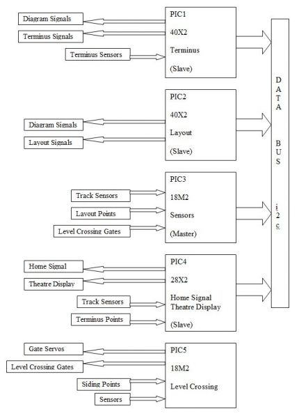
This shows how the microprocessors are connected together and what components are connected to each. Due to the lack of sufficient input/outputs ports on each processor certain inputs are shared across two or more processors using a data bus and the i2c data protocol. The protocol itself doesn't need to be understood - just the commands of how to send or receive data to or from the "master" processor (PIC3) and even the understanding of the commands can be challenging! It took me quite a while to understand where on each processor the bits of data is either being read from or written to - there can be three memory areas that can be accessed by the protocol and some are also normal variable locations that could easily be overwritten by the running program. Even the write-up for the commands can seem a bit complex in this respect and not overly clear. Or maybe it's just me.
To aid my understanding of the i2c comms, a small, simple program was cobbled together to allow some practice with programming the comms/i2c between a pair of processors (and a couple of switches) on a breadboard. This way I could get myself some understanding of writing and reading the data (settings of the switches connected to one processor or the other) and displaying the result on a couple of LEDs on the other processor depending on those switch settings. Anyway, I digress.
Posted
Full Member
Incidentally, the current needed for an LED is usually taken as around 10-15mA, whereas to drive the same LED via the ULN drivers is around 1.4mA from the processor port - quite a saving on power that would need to be provided from the processor - and any number (within reason) of LEDs can be connected to any one output port of the ULN chip. The voltage drop across the ULN devices is around 0.9-1.0v so, in theory, to obtain the same LED current (and resultant LED brightness), the current limiting resistor would need to be around 900ohms rather than the more normal 1k (from a +12v supply). Personally, I hardly think the difference is that noticeable.
In fact, and to correct the statement above about the ULN driver chips feeding power to the LEDs, it's actually the other way around. The LEDs are all fed with a permanent +12v and the LEDs are turned on by the ULN driver ports being driven ON by a positive output from the processor, which then causes the cathode of the LEDs effectively being connected to ground (0v) via the internal Darlington output transistor pair on each port of the ULN device. Up to 500mA can be sunk through each of these ports - that's quite a few LEDs that could effectively be connected from one processor port (unrealistic as only two or three would be normally needed - the signal head itself plus any mimic/monitor LEDs).
As noted way back in my post #2, the programming is all in the BASIC language and which simply comprises a series of "IF this condition….THEN take this action" commands. I say "simply" a series of commands, but in reality there can be quite a lot of possibilities as to what action to take dependant upon the state of the next signal as well as the one after that and whether a train is already in the next section and also which way any points have been set beyond that signal. Simple enough where there is a long stretch of uninterrupted track with just a couple of signals to contend with, but add in a few points, maybe both diverging and converging, and it can be not quite so simple. At least the programming application has a simulation mode so the program can be tested either in slo-mo or step-by-step (everything except for the i2c comms). And this programming has taken me months to get it sorted, with many restarts as fresh ideas on how to do it came to mind. No doubt there's an even more compact or efficient way of doing it, but this appears to work (in simulation). And the processor itself is said to be capable of around 2000 individual commands per second - not that I've counted them! So it should be fast enough to cope with whatever might be going on.
As I've mentioned previously, overall there will now be complete control of the Terminus outgoing signalling (points still need to be manually set - maybe another day even this could be automated), the Layout signalling taking into account a working level crossing operated by servos activated by signals taken from in-track sensors together with the protecting signal that remains at danger until the gates are fully open for train traffic, right round to the Terminus Home signal and Theatre Display which shows the active (arrival) platform number and which remains at danger until a train approaches it - this to force the train driver to slow the train before entering the Terminus itself.
The past day or so I've been checking all the inputs (sensors, switches) and making sure they work as expected. And also the outputs (using a multimeter) before plugging the processor in. One issue I found has been a couple of signals (4 aspects) that are effectively wired wrongly (with a common 0v connection and not the common/permanent +12v as used elsewhere on here) and they are in a position I just cannot get to with a soldering iron and change. So a revised output has had to be made whereby I now take their red outputs direct from the processor and the yellow aspects direct from the 7404INVerter rather than going through the ULN drivers - although the track diagram will still work as originally planned - so maximum current capabilities of the processor are still within spec.
So, although it's not fully up and working as yet, that is the final plan that is coming close to completion. Hopefully it won't be too long before I can call it done and I can get back to operating the trains again and maybe adding a bit more scenic stuff.
So that's about it for automating signals (and the Level Crossing). Unless I can find the time to add a semaphore signal (or two) somewhere on the layout in place of a colour light signal. Something to think about, probably making use of more servos and another processor. And then maybe a project to update the Turntable as it doesn't line up 100% to the exit roads - it's close, but can at times be far enough out to cause a derailment.
As mentioned before and for clarity, I have no connection to the makers/distributors of the (Revolution Education's) PICAXE or the Microchip series of microprocessors, upon which the PICAXE processors are based, other than as a user.
So to recap this part of the project. Two processors, one for the Terminus controlling exit 6 roads/platforms, each with a two-aspect red/green signal on a gantry plus ground calling-on/positioning signals for entry into the sidings and turntable area. The second processor controls the flow through nine signals, three of which are hidden but visible on the Track Diagram of the layout. The signals are seven three-aspects and two two-aspect red/yellow signals. Each signal having its own sensor. Tied into this module is the Home Signal/Theatre Display processor controlling access to the Terminus. Also tied into this is the Level Crossing processor.
So quite a lot going on making automatic signalling across a layout a real possibility with a few processors, miles of wires, quite a few hours of programming time and a fair bit of patience.
That's it for now. I need a lie down in a dark and quiet corner with some soft, gentle rock music playing before I start on the next project.
Posted

Full Member
The fact that these “blokes†were highly skilled humans with years of experience and logic capacity and that accidents were so very rare is a fair indicator of what you are trying to achieve electronically Dave.
Please keep it coming. I would like to do some microprocessor programming and automation one day and will look to your work for guidance.
You can do it, finish it off. It took me six months to rebuild the Llandyfriog Junction on NE with electronically actuated points. There is room in the Llandyfriog signal box lever frame for signal actuating levers… just need a roundtuit!
All the best
Marty
Posted
Full Member
I have absolutely no idea how you remember all this Dave, let alone how you learnt it all in the first place ! Did you already know what did what or did you come up with a function requirement and then find out which "black box" would do it ?
Is this the sort of electronic installation they would use on the real thing - albeit somewhat beefed up ?
Considerably less physical than Marty's muscle bound signalman pulling his levers. …….
'Petermac
1 guest and 0 members have just viewed this.