Peco 00 Turntable Kit - Project By Perry
Posted
#408
(In Topic #160)

Legacy Member
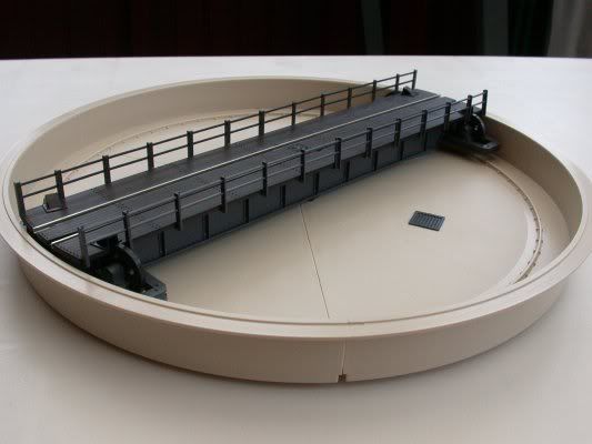
In the Personal Layouts (East Walsham) part of this forum, Bob asked me to provide an image of the Peco Turntable kit as it comes 'out of the box' for the benefit of anyone thinking of adding one to their layout.
I decided to put it here as hopefully being a more suitable place for it.

I was quite impressed to see that even the draincovers in the bottom of the well have been provided as separate mouldings. It makes things a lot easier for painting and detailing. The kit looks straightfoward enough to build with the three segments of the well fitting together nicely in a dry test-fit. There are good instructions covering assembly, wiring and basic motorising or the fitting of a mechanism.
Be aware though, this is quite a big item and needs a 310mm diameter hole to sit in, therefore as I found, if your baseboard cross-braces are at 12" centers, it won't fit. Using the size timber I did, nominal 2"x1" planed, I only had 285mm to play with, so I'm probably going to have to build an extra triangular baseboard to accommodate it in one corner.
Perry

Posted
Legacy Member
I have copied this post across from my East Walsham thread:
First tips about building the Peco turntable kit:
When fitting the plunger housing (part 4) and the bearing block (part 5) beneath the middle of the deck, it's handy to have a couple of small clamps to hold the whole lot together. I used the small ones that 'ratchet up' by squeezing a trigger to adjust the tension. Just holding them together with ones fingers doesn't look as though it will give a strong enough joint, given that all the rotating forces will be borne at that point.
Also, make sure you complete Step 2 before the solvent or glue has dried on the parts assembled in Step 1. It will make minor realignment of the table sides easier.
The metal plungers, (part 7) go into the holes in the deck before the springs (part 8). The rails, which need to have bevels filed on the ends, then hold the springs in place.
Perry
Posted
Legacy Member
The outriggers that hold the wheels at the ends of the deck are now under construction. I was pleased to find that the wheel axles are made of metal. The wheel mouldings are well executed and are easily removed from the sprues, being attached at one point only. No trimming of the wheels was needed apart from at the points at which they were cut from the sprue. In fact all parts of the kit so far have been remarkably flash-free. The plastic used cuts easily and cleanly and the parts fit together really well.
As with my plastic scratchbuilds, I'm allowing plenty of time for the glue and solvent to dry. There's no point in rushing it and finding that it has warped out of shape.
I take some photographs of the various parts before they are painted or installed in the baseboard.
To be continued.
Perry
Posted
Legacy Member
My guess is that the moulds that Peco have used for this kit are very new; everything is very crisply moulded and the detail is excellent. The mouldings are strong and substantial without being too 'heavy' for the model. I'm well impressed so far. :-)
I'm continuing to work on the outriggers this evening. I have found that it is possible to glue the bearing blocks (part 14) in place with the metal axles in situ to make sure they stay aligned whilst leaving the wheels off. There is then absolutely no chance of getting glue on the wheels themselves. When the bearing blocks are dry, the metal axles can be slipped out, the wheels dropped in and the axles replaced. This is slightly different to the printed instructions but safeguards the wheels, making sure they will rotate freely.
Perry
Posted
Legacy Member
I was pleasantly surprised how freely the deck rotates.
The electrical continuity was checked with a multimeter, ensuring that current could flow from the power input tags below the well, through the plungers and springs and thence into the rails. All was well first time round with no need for any adjustments.
This kit is well within the capabilities of even an inexperienced modeller. The only tools needed were a craft knife, a small needle file, a pair of snipe-nosed pliers and a 14 pound sledgehammer….
Actually, I lied about the sledgehammer. The kit goes together very easily and didn't need any attention from a 'persuader'.

Pre-installation photo's to follow soon.
Perry
Posted
Legacy Member
Robert said
Does the kit have instructions for fitting a drive motor and choice of gearing Perry?
I have obtained a suitable motor and gearbox to power the turntable. I will be covering this, with pictures, in a later post, if that's OK. I don't want to provide too much information too quickly, so bear with me as I work through this project and hopefully, all will be revealed in due course.
Perry
Posted
Legacy Member
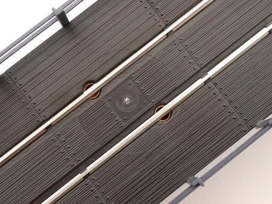
Here is an overview of the (more or less) completed kit:
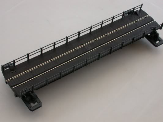
The deck by itself:
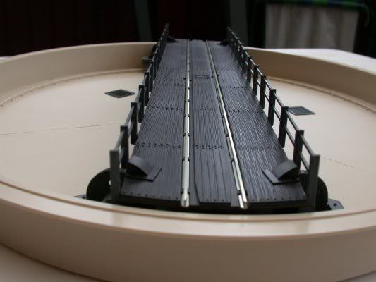
and an end view of the deck:
And now for the more 'technical' details:
Building the outriggers using the method I mentioned previously resulted in the wheels being able to turn freely. The metal axles can be seen in this photo. The outrigger is shown upside down for clarity.
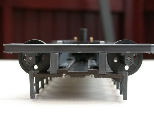
The axles are only a push-fit in the bearings so there is no problem with putting the wheels in after glueing the outriggers up nice and solid. The ends of the axles can be seen in this image.
These semicircular contacts….
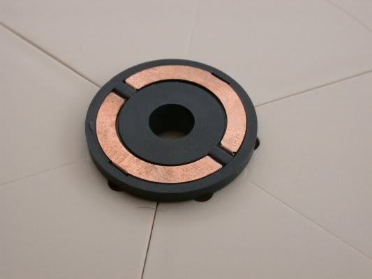
are simple to bend to shape using a small pair of pliers. They push through slots in the bearing and fold over at the back to hold them in place.
They protrude beneath the well and provide the power connections in the form of the two metal tags seen in this image:
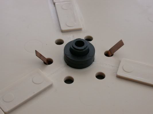
The plungers mounted under the deck….

ride on the semi-circular contacts shown above to supply current to the rails.
A pair of springs are activated by the plungers. These press against the undersurface of the rails carrying the current from the plungers. The springs can just be seen in this image:
Future adjustment would be very easy as all that is required is to slip the rails out of their mounts, 'tweak' the springs, then reassemble in the reverse order.
I have not fixed the deck in position yet as I feel it would be advisable to be able carry out final adjustments when the turntable well is fitted into the hole in the baseboard.
There was nothing difficult about assembling this kit; in fact it was one of the easiest kits I have ever built. I am very pleased that I chose the option of using this kit rather than trying to scratchbuild a turntable. As I said above, the quality of the kit and the ease of assembly is excellent. If I were to make any changes at all to the manner of assembly, it would only be to leave the wheels off until the bearings were set. No great modelling skills are needed to make a success of this kit. Just take reasonable care and clean off the burrs from where the parts were joined to the sprue and all should be well.
By the way, for all you plastic modellers out there; don't throw the used sprues away. they are a valuable source of raw material! :-)
I have purchased a motor and gearbox assembly to power the turntable and I will cover the mounting of this in later posts.
I hope this post will encourage some of you to grab one of these kits and have a go yourself. Go on - it's easy! :grin:
Perry
Posted
Legacy Member
The painting should be easy enough. It's one of the reasons I haven't made the deck to well fixing permanent yet. By slipping off the retaining collar beneath the well, the deck just lifts off. The well will need some serious dirtying up at the very least. The deck would benefit from some muck, grime and rust being applied, with the details - rivets, bolt heads, etc., brought out by a judicious bit of dry-brushing (as per the technique described in my scratchbuilding posts.)
Had I painted it all before assembly, I would have had to take great care not to paint over the areas where solvent or glue was to be applied. This seemed to be the much easier method - and I'm all for making things easier! :wink:
Perry
Posted

Full Member

Posted
Legacy Member
1. Cut a hole in the Sundeala top, then chop the cross braces out to the appropriate depth to allow the well to be inserted. Sounds quick and easy but I have reservations at to how well an electric router would deal with something as soft as Sundeala. At the very least it would be extremely messy. I don't fancy trying to use an electric jigsaw because of the cross-braces beneath getting in the way. I would have no control over the depth of the cut.
2. Cut a rectangle out of the Sundeala. Cut away the present cross-braces and replace with new ones, leaving a ledge all round. Insert a rectangle of 12mm MDF with a hole cut in it for the well, so that it sits on the ledges. That way the whole turntable unit would be more easily removeable for maintenance or repair.
Benefits of the using the second option would be that a mounting bracket for the motor and gearbox would be easier to fix securely to the piece of MDF - not so easy with just fixing to the Sundeala which is a lot softer. Also, the well hole could be cut in a smallish, easily handled, piece of 12mm MDF instead of in a 4ft x 2ft piece of Sundeala already fixed to a frame. I also think the hole would be easier to cut more accurately on the workbench using a router rather than trying to manipulate a whole baseboard.
There is still lots to think about. It's probable that I will choose option 2, but I'll let you know when I have reached a decision.
Perry
Posted
Legacy Member
"How To Make A Hole In A Piece Of MDF"!
However, when I mentioned the probability of using a router to do this job on the old forum, there were a few queries regarding the use of this tool. So please bear with me if Im' "teaching Granny to suck eggs" :oops:
Anyway, the sub-baseboard for the turntable well was begun this morning.
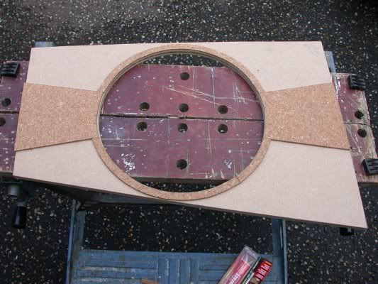
As I was using 12mm MDF and needed to cut an accurate circle 310mm in diameter, I quickly realised that an electric jigsaw would not suffice.
I therefore decided to use my electric router with a trammel arm. This arm slides into holes either side of the router body and is held in place by two thumb screws.
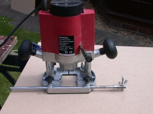
The centre point locator can be seen at the end of the trammel arm. This can be adjusted for depth using the wing nut.
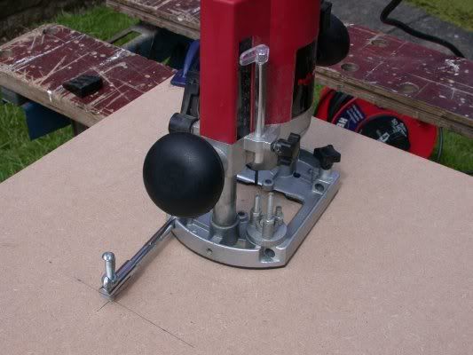
The centre position for the well was marked out and a 5mm hole drilled all the way through the MDF, making sure that the drill bit was kept perpendicular to the surface.
A few pencil marks were made at a radius of 155mm from the centre point, just to check all was OK.
After the trammel arm and the centre point locator were attached, a narrow straight cutting bit was fitted to the router. The length of the trammel arm was adjusted so that with the centre point locator in the pre-drilled hole, the outer edge of the cutter was just touching the pencil marks. This was checked at several points on the circumference of the circle.
When all was well, the MDF was turned over, so that it was upside down. The first cut was made to just over half the depth of the material. This makes cutting easier, tidier, and minimises stress on the router and the cutter.

Always cut anti-clockwise when cutting a circle. The rotation of the motor pulls the cutter into the work rather than trying to force it away, resulting in a neater job. Don't rush the cut. Let the tool do the work for you, using steady light pressure on the handles. Too fast and you risk damaging the cutter; too slow and the workpiece can get scorched.
When the cut on the reverse side is complete, turn the piece over and place the centre point locator in the hole again. A second cut, again anti-clockwise, from the top side will complete the job.
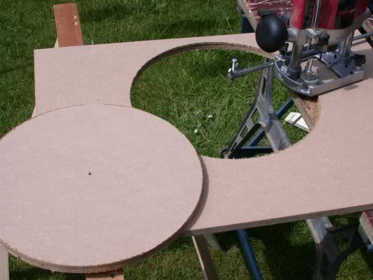
Remember to support the disc of waste material so that it doesn't break off before the cut is complete.
The inside of the cut can be lightly sanded if required, taking care not to take off too much material.
The turntable well just slots neatly into place.
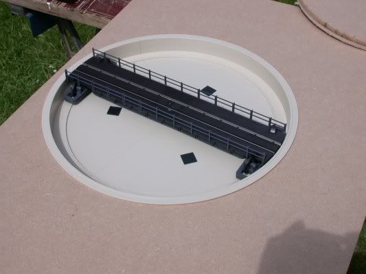
Then, as the saying goes, the job's a good'un! :grin:
It now just remains for the sub-board to be installed. I will trim it to shape later so that nearby main-line tracks won't pass over the corner of it; otherwise subsequent removal would prove very tricky indeed. :? Also, I think I may have to put some cork under the rim of the well. Not only will this help deaden the noise but also it will bring the turntable rails up the the level of the access roads.
Perry
Posted
Legacy Member
There's still a fair amount of work to do on this project: set the sub-board in place, lay cork under the rim, painting, mounting the motor, laying the access roads, wiring, etc., so I think I have enough to be going on with for the time being. :shock:
Perry
Posted
Legacy Member
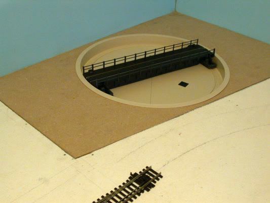
The turntable MDF sub-base was cut to shape and let it in to the Sundeala baseboard top. Having cut the sub-base to shape, I laid it on top of the Sundeala, drew around it and then cut the Sundeala away. The sub-base fitted pretty well first try - almost too well, in fact. I will need to plane the thickness of a gnat's wotsit off two of the sides of the MDF tomorrow. The fit is so snug at the moment that the slightest bit of expansion in the warm weather may make the sub-base too hard to remove without causing damage.
Having cut the Sundeala top away and put the sub-base in place, I was able to mark the baseboard framework through the hole previously cut for the turntable. That way I could easily see where the cross-braces needed to be cut away to allow for the depth of the turntable beneath the baseboard. I removed about half the depth of the framing to allow enough clearance - a tricky job because it wasn't easy to get a saw between the cross-braces. :? It ain't pretty under there, but it does the job (and no-one can see it :twisted: ).
Despite all the above, I then ran into a snag; well there had to be one, didn't there? :evil:
One of the remaining cross-braces was situated directly beneath the pivot hole of the turntable deck! I needed room for the motor and gearbox to be fitted so that part of the framework was hacked out ruthlessly. The resulting 'loose end' of the cross brace was secured with a screw. I decided that the 12mm MDF has enough intrinsic strength and rigidity not to need the brace I cut away. I now have ample room to fit a mounting bracket to support the motor and gearbox.
I did have one stroke of luck though; I found a 6 volt mains adaptor languishing in one of my junk boxes - just what I needed to power the turntable motor. I connected the motor up with some temporary leads, and whadya know - it worked! The gear box is a little noisy running without a load, but with a little silicone grease on the gears and a cork-lined mounting-box if necessary, it should run a lot more quietly.
A little more fiddling about with the sub-base to get the fit exactly the way I want it and I will be able to work on the turntable mechanism and detailing away from the layout. It will be much easier than leaning across the baseboard or crawling about under it. :-)
Perry
Posted
Legacy Member
Perry
Posted
Legacy Member
I worked out early on that the rim of the turntable well that sits on the surface of the sub-base was going to need to be raised on cork for two reasons. Firstly, the level of the approach rails were 3.2mm higher than the table rails; the thickness of the cork track bed. Secondly, I think it might help the turntable motor to run more quietly by absorbing some of the vibrations that might make the MDF 'drum' a bit.
With this in mind I set about working out, pretty much by trial and error, where the entry and exit tracks would sit. I then cut a cardboard template for the 'fan' shape needed to take these. I cut four half-inch (12mm) strips of cork tile to use around the edges of the pit.
I used impact adhesive to stick the cork to the MDF. As the curved strips naturally tried to return to their initial straight state, I needed an adhesive with plenty of 'grab' to hold the curves.
I glued the cork pieces in place, fixing the fan shapes first. Then I carefully bent the narrow strips round the edge of the pit, making sure they were well stuck down before moving on. Four pieces, two each side, did the job. I trimmed them to length in situ with a sharp knife.
The sub-base then slipped neatly into place.

Having made sure there was no excess adhesive anywhere, the turntable was pressed gently into place so that the rim sat snugly on the cork. I won't fix it in place yet as the motor still has to be mounted and the wiring needs to be done.
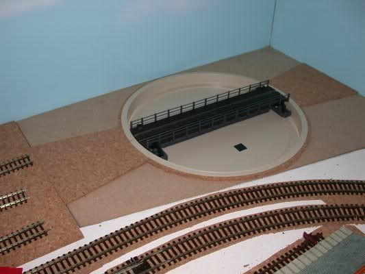
Laying the approach and exit tracks is next on the turntable project list.
Perry
Posted
Legacy Member
Perry
Posted
Legacy Member
Having got the section of track lined up to my satifaction, I made some temporary connections to the two tags beneath the turntable and also to the approach road rails.
I expected to have to mess about with a DPDT (double-pole double throw) switch to change the polarity when the table was turned through 180 degrees.
However, I was pleasantly surprised to discover this wasn't necessary as long as the two pairs of connections were the right way round to start with. I guess I had a fifty-fifty chance of getting it right first time. :oops: Yep, you're right, I got it right on the second attempt. I only had to swap a pair of wires over so no big problem.
I ran a loco onto the turntable, turned the table by hand ('cos I haven't installed the motor yet), and then ran it off again. One of the real advantages of DCC then revealed itself; if the loco is set to reverse onto the table, there is no need to change it's direction when it comes off. Reverse is reverse for that loco, regardless of the polarity of the rails. :grin:
Peco have arranged the turntable wiper connections so that it sorts it all out automatically for you - provided you read the simple instructions regarding the orientation of the connectors when you install it. Excellent!
More to follow soon.
Perry
Posted
Legacy Member
Maplins reference number for this switch is FH07H.
Perry
Posted
Legacy Member
Gwent Rail said
Do I assume correctly that the only way to stop at the right point is by eye :?:
If so how easy is it to get it right :?:
In order of asking:
1: Yes, by eye only. There is no latching mechanism for aligning the access road. Fortunately the turntable is pretty close to where the controls will be.
2: I don't know yet as the motor and gearbox have yet to be fitted. However, I did read somewhere that because the gear ratio used in the gearbox I bought is very low, the table turns very slowly. I'm hoping that with a little practice, it won't be too difficult. I like a challenge! :grin: I think it would take a fair bit of engineering know-how to build an indexing system. I don't have that sort of know-how, or the workshop facilities that would need to go with it.
Perry
Posted
Legacy Member

The rails were soldered to the PCB either side of the join. I brushed a little flux paste where I intended soldering first, then used a decent-sized soldering iron - 30 watts - to get plenty of heat into the job quickly. That way the heat doesn't travel too far along the rail and melt the sleepers. This can happen when a soldering iron that is too small for the job is held against the parts for too long.
The rails were then cut through with an mini-disc cutter, thus ensuring that they will always align perfectly.
The sub-base was then removed to allow further work to be carried out.

This included the fitting the over-run roads which are difficult to get at with the sub-base in situ.
The whole lot was turned over and the motor and gearbox assembly plugged in to the turntable pivot. A couple of wires were soldered to the turntable pick-up tags in readiness for connecting up later. A scrap piece of timber was then mounted underneath the sub-base using a couple of metal brackets that happened to be lying around in my garage. The gearbox was secured to the timber with four small screws.
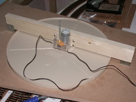
Since the last picture was taken, I have also soldered a couple of wires onto the turntable motor connectors.
A trial run of the turntable has shown that it will need a little bit of 'fettling', just to get it to run smoothly. I put some Peco Lube on the gearbox and bearings before I screwed it to the support - 'cos otherwise you can't get at it! I expect performance to improve as the motor and gears settle down.
I think I am getting some slippage of the plain metal shaft in the plastic bush beneath the turntable deck. As soon as I'm happy that everything can be fixed permanently, I will Araldite this into place.
So, apart from finishing the wiring, the turntable is all but complete. I shall paint it when I landscape the layout so that it blends in with its surroundings.
That just about concludes the turntable project. If anything interesting crops up during the 'tweaking' period, I'll let you know! :grin:
Perry
1 guest and 0 members have just viewed this.