The art of compromise.
Posted

Full Member
Finally gettiing out of my system.
Welcome to the club of powered points. I feel your satisfaction. Give it a layout or two and you’ll be installing servo motors like Max. :shock:Marty

Posted
Full Member
I doubt it Marty. I find electrics totally confusing.
Terry
Posted
Full Member
Last night I decided to lay the track in the fiddle yard, consisting of a 'Y' point and two sidings…
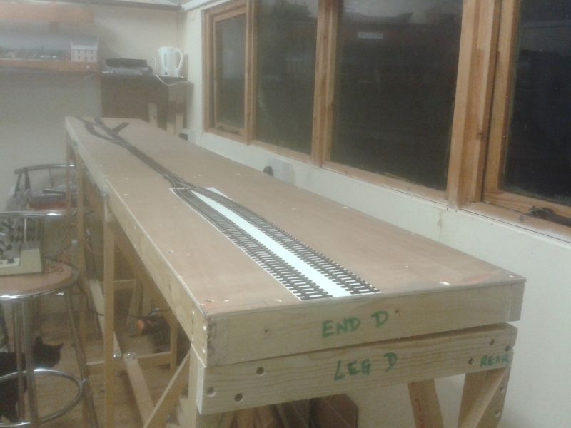
The point and track were simply pinned to the baseboard using Peco track pins. After soldering wires to the rails at the toe of the point to pick up the current from the next board, I noticed that one of the rails had become detached from the sleepers and was badly misaligned. I assume that the damage was caused by the heat from the soldering iron. The fixings at the toe of Peco points do not appear to be very robust at the best of times. Fortunately, I have bags of track spikes left over from my O gauge days. I decided to reposition the offending rail and drive a spike each side to hold same in position.
Terry
 Last edit: by col.stephens
Posted

Full Member
Siliarly, the problems with displaced rails on points were solved by the insulated joiners. They seemed to hold well enough although I never thought of spikes ………………..
Nice looking woodwork. :thumbs
'Petermac
Posted
Full Member
Thanks Peter. The woodwork is basic but it will suffice. Unfortunately, I can't use rail joiners at the toe of the 'Y' point as it is at a baseboard joint. Mind you, I hadn't thought of it anyway. I must bear that idea in mind for future use.
Yesterday I screwed a piece of mdf to the underside of the baseboard frame to act as a shelf to support the Gaugemaster 100M controller. A short length of aluminium angle was glued to the front of the shelf with the trusty poundshop 'Hard as Nails' adhesive, to prevent the controller from falling off. The track diagram was drawn on the mdf with a permanent ink pen and four holes were drilled in the appropriate places to take the switches for the point motors. The controller shelf will need to be detachable to pack the layout when exhibiting and also because I want to be able to fit it to the front of the layout for home use. For the switches it became apparent that I require a plug-in connector with twelve pins, which of course I haven't got, so things came to an abrupt halt. I ordered said connector today on ebay and took the opportunity to order more wire in various colours for future use.
Whilst waiting for the connector to be delivered, I could get on and paint the sides of the rails.
Terry
Last edit: by col.stephens
Posted
Full Member
Change of mind today. I decided that it would be preferable to operate the layout from the front. Firstly, one can easily engage in conversation with visitors, and secondly, you usually get the best view of a layout from the front, not peering down from above over the backscene. I have worked out a way of attaching the controller shelf to the front of the layout utilising coach bolts for quick and easy removal. I'll show pictures when it is done. The controller shelf will now be situated in front of the fiddle yard with the option of a walk about hand-held controller to get close to the action at the far end of the layout.
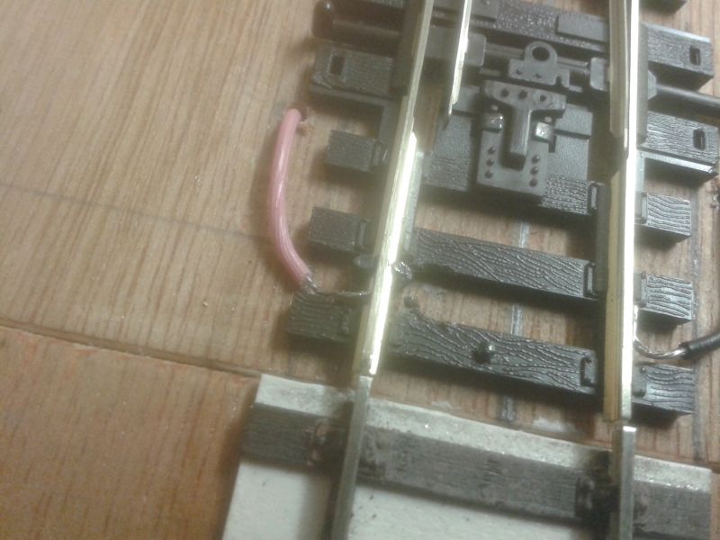
Speaking of the fiddle yard. I have decided not to worry about changing the polarity of the 'Y' point and to rely on blade contact, i.e. use it as intended straight out of the box. Accordingly, it just required a simple means of moving the tie-bar. Herewith a picture of Terry's patented point lever, Mark 1…
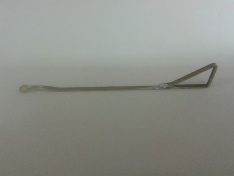
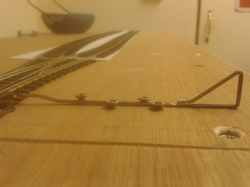
As you can see it consists simply of a small washer soldered to the end of a short length of bent rail. The washer is pushed onto the small 'pip' at the end of the Peco tie-bar and the lever is held in place with small screws, thus…
More soon.
Terry
Last edit: by col.stephens
Posted

Site staff
Ron
NCE DCC ; 00 scale UK outline.
NCE DCC ; 00 scale UK outline.
Posted
Full Member
Good idea, thanks Ron. I'll bear that in mind for future use.
Regards,
Terry
Posted
Full Member
'Petermac
Posted
Full Member
Thanks Peter, I'll bear that idea in mind too.
Regards,
Terry
Posted

Full Member
Bent rail and an omega loop won't work. The loop is intended to take up any overthrow, and as stated above, will act as a shock absorber. Code 50ish rail is too big for a small loop, P/B wire or r/c control wire (steel) is much better. Although this is just an extension of the throw bar, not a WIT, so the point spring does the work.Additionally Terry, I'd be inclined to add an omega loop to the mechanism to absorb the "shock" as you change the point. They're not very well secured and I think you may find it all comes adrift fairly quickly - regardless of how careful you are - there's usually quite a lot of pressure at shows. :hmm
Nice approach Ed (and Terry).
Nigel
©Nigel C. Phillips
Posted

Site staff
Not guilty M'laud

But agree with Nigel, if you've got a fairly solid bar to the point you don't need an omega wire Terry.
Omega wires take up the slack/flex in WIT systems, and if the outer tube is really solidly fixed still aren't needed (sorry Peter).
Ed
Last edit: by Ed
Posted
Full Member
I'm standing in the corner as I write ………………………………………….

'Petermac
Posted
Site staff
Very similar to Terry's set up, but using a switch as well.
Ed
Posted
Full Member
Easy for you to say that - you're not the one standing in the corner having tomatoes thrown at you ……………………. :thudNo worries Peter, ………………………………………..
Ed
'Petermac
Posted
Full Member
As mentioned previously, I have now assembled the shelf for the controller. It will need a coat of paint to smarten it up but here it is…
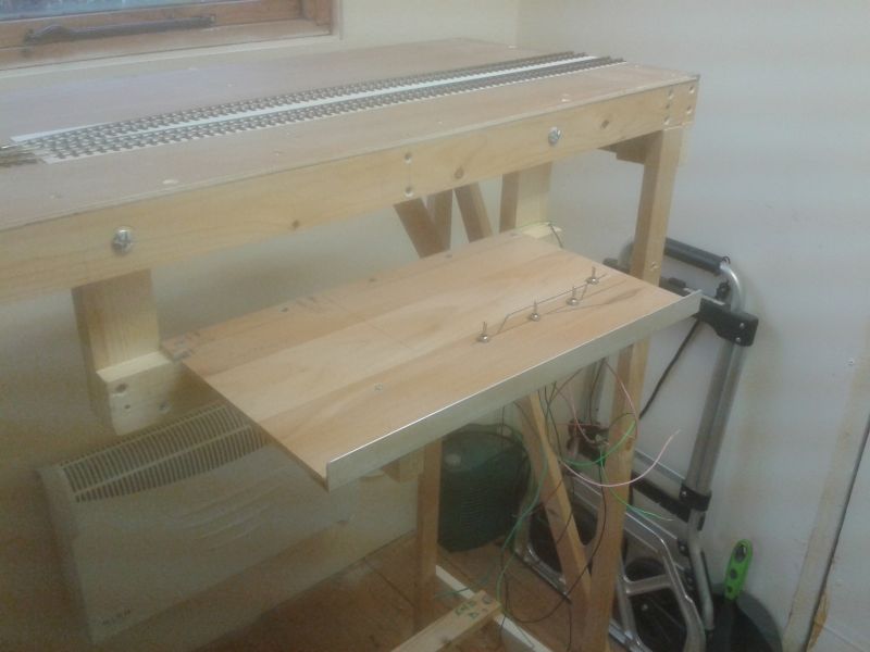
Fixed with two coach bolts to the baseboard framing for quick removal.

Extra support underneath to take the weight of the Gaugemaster 100M.

The gap is required behind the controller as, I realised too late, the hand-held controller fits into the rear of the Gaugemaster 100M with a ruddy big jack plug and requires sufficient clearance behind the unit. Of course I didn't think of this when selecting the depth of the shelf. The track plan and switches are now the wrong way round as I had decided to move the controller from the back of the layout to the front. This will all be reversed in due course and a better looking track plan will be substituted.
Terry
Posted

Full Member
Staying on the thread Kevin.
Posted
Full Member
Thank you Kevin, very kind of you. I am submerged in the process of wiring the layout at present but hope to post more soon.
Best wishes,
Terry
Posted

Full Member
Posted
Full Member
I like that. :thumbs
Terry
1 guest and 0 members have just viewed this.