The art of compromise.
Posted
#240032
(In Topic #13292)
Full Member
Finally gettiing out of my system.
In October, 1978, The Railway Modeller published an article by Roy Link called 'The art of compromise.' The article suggested that a blend of diorama and a working layout could provide the answer to lack of space and inertia brought about by an 'undecorated expanse of baseboard.' The author provided a plan of a small country terminus with a single short platform with run round loop and two sidings. One siding housed a goods shed and the other coal bins. There was also a small ground frame and a weighbridge and office. This was all achieved (in theory) on a baseboard measuring just six feet by one foot. The article suggested that, although it would be possible to shunt the yard using the single line in front of the station platform, the layout would be enhanced by the addition of a small fiddle yard. I filed away the article with a view to building the layout sometime… I often thought about the magazine article and often got it out for another read through but never actually got around to starting it.
The years rolled by and various articles appeared in the model railway press by other people who had also got the 'art of compromise bug'. But they all had the same thing in common. In planning and attempting to build the suggested layout, they found it was not possible! The author had simply shoe-horned too much detail into the width of the baseboard beyond the end of the platform. The author had also placed a turnout exactly halfway along the six feet baseboard making it impossible to divide the baseboard into two three foot lengths for storage and transportation.
The latest published attempt at 'the art of compromise' appeared in the October 2018 Railway Modeller by Chris Ford. Part of the original article was re-produced along with the original track plan. I was sufficiently intrigued to buy the magazine and decided at long last to slay this particular dragon and attempt to build it at last.
Terry
 Last edit: by spurno

Posted
Full Member
I decided to use Peco code 75 turnouts together with C&L track as I already had these to hand. First off I decided to alter the plan slightly and move the turnout away from the centre of the baseboard to allow it to be divided in half. I also decided to include two catch points in the sidings where they meet the 'main line.' I had plenty of wood to hand retrieved from previous layouts. I also had some lengths of 5mm thick plywood which I decided to use as the baseboard surface. The plywood had previously been cut to fourteen inches wide so I decided to utilize those extra two inches to try and achieve something akin to the original plan. The scenic baseboard measures six feet by fourteen inches with a small board for the fiddle yard. I think it's actually thirty inches long but I can't swear to it. I must measure it when I next visit the shed.
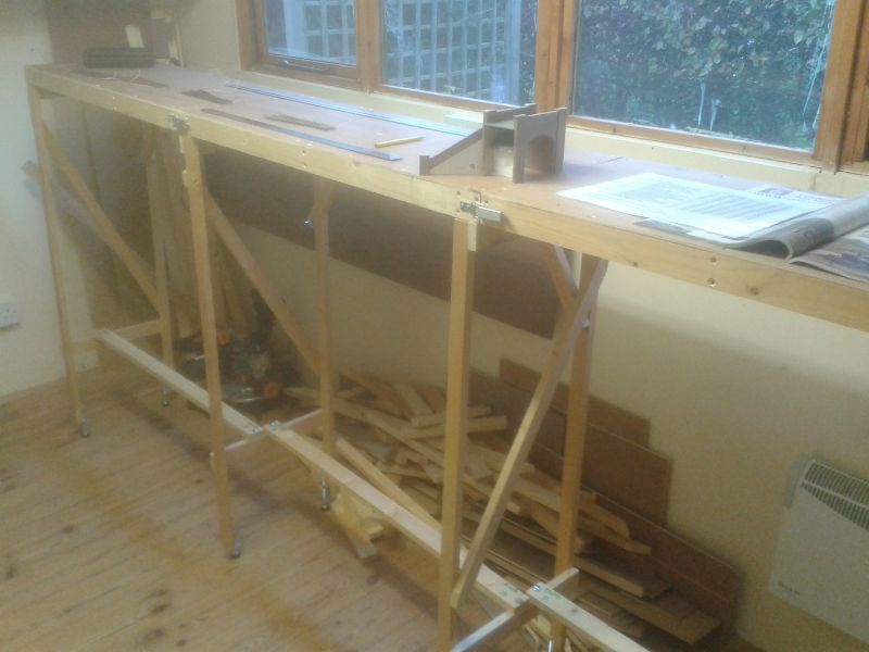
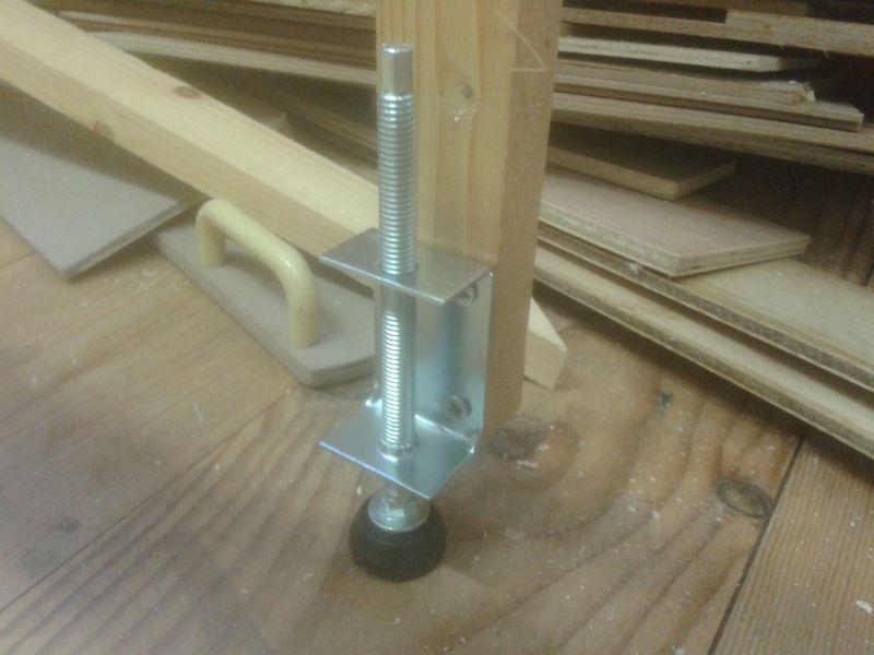
Nothing remarkable about the baseboards although I have for the first time used catches to join the boards together with metal dowels for alignment. I also fitted adjustable feet as my shed floor is as level as the North Sea on a stormy day!
Last edit: by Barchester
Posted

Site staff
Ron
NCE DCC ; 00 scale UK outline.
NCE DCC ; 00 scale UK outline.
Posted
Full Member
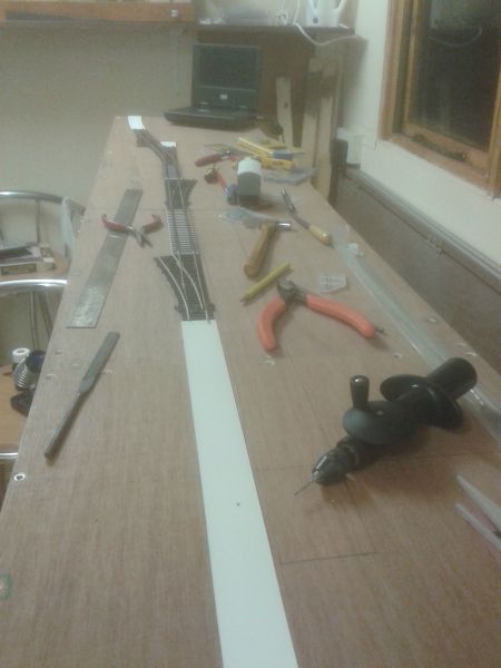
I drew out the track plan on the baseboard surface and drilled and filed small slots where the turnout tiebars were situated. This was so that I could utilise the small hole in the Peco tiebars for operation. At this stage I decided to use, for the first time, point motors to throw the tiebars. A small bit of research showed that Gaugemaster Seep point motors, PM1, contain contacts to change the polarity of the common crossing (frog). I ordered the four motors required and set about laying the track.
Last edit: by Barchester
Posted
Full Member
Terry
Last edit: by Barchester
Posted
Full Member
All track has been laid and connecting wires soldered in place. This view shows the general layout of the yard…
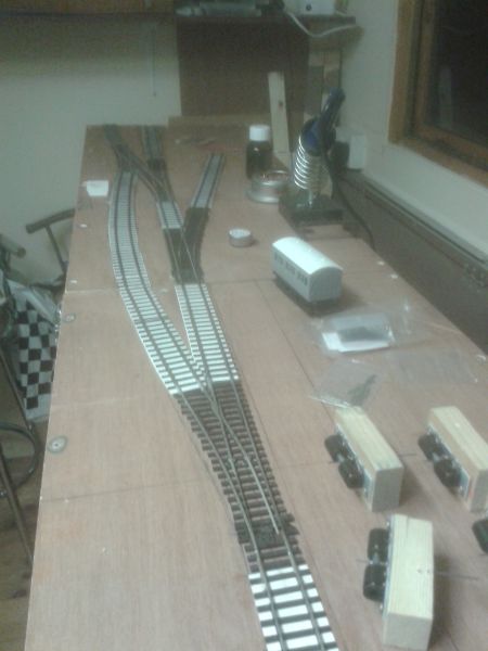
You can clearly see the run-round loop with a small loco spur beyond. This goes right up to the baseboard edge so that the intended buffer stop may be removed for future expansion of the layout if desired. Likewise, the fiddle yard board may be removed and extra boards fitted. The siding to the right will house the coal bins and the weighbridge. The goods shed will be situated to the right of the siding straight ahead.
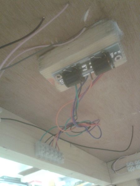
Having such a thin baseboard surface means that it is not possible to screw the point motors directly to the underside. I decided to cut small blocks of wood and drilled/filed small slots along the centre line…
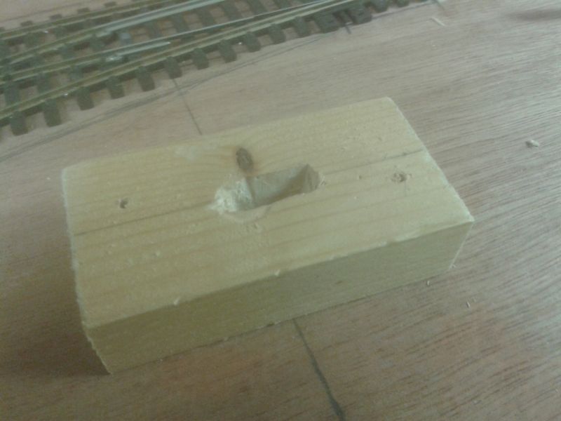
The point motors were screwed to the blocks with the operating rod passed through the slot. The idea is that the blocks are now glued to the underside of the baseboard, directly under the tiebar. I shall probably use the poundshop version of 'no nails' for this job. Here are the four completed blocks with motors in place. The relevant wires to the point motor contacts need to be soldered in place before the blocks are attached to the baseboard. I shall run the wires to nearby terminal blocks to aid quick replacement should any motor fail in service.
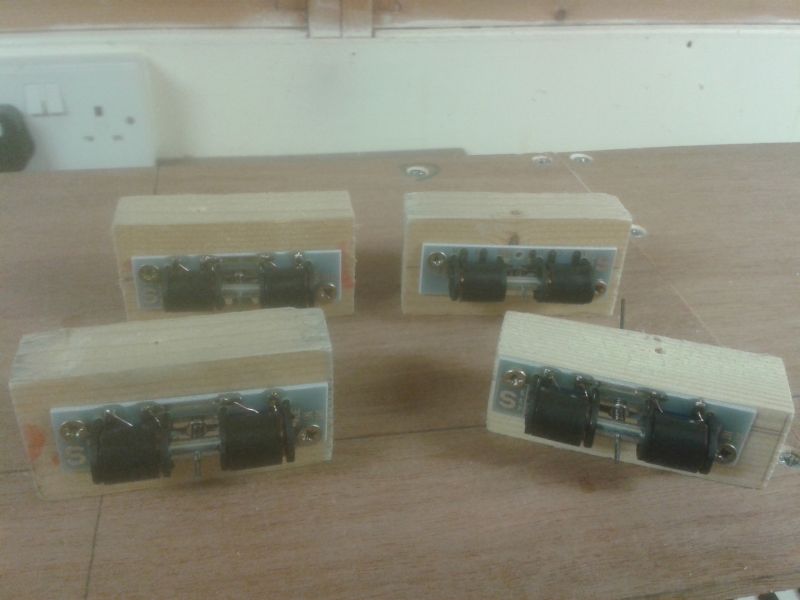
The right front block has the motor adjacent to the edge. This is to be fitted to a turnout which is very close to baseboard framing.
Terry
Last edit: by Barchester
Posted
Full Member
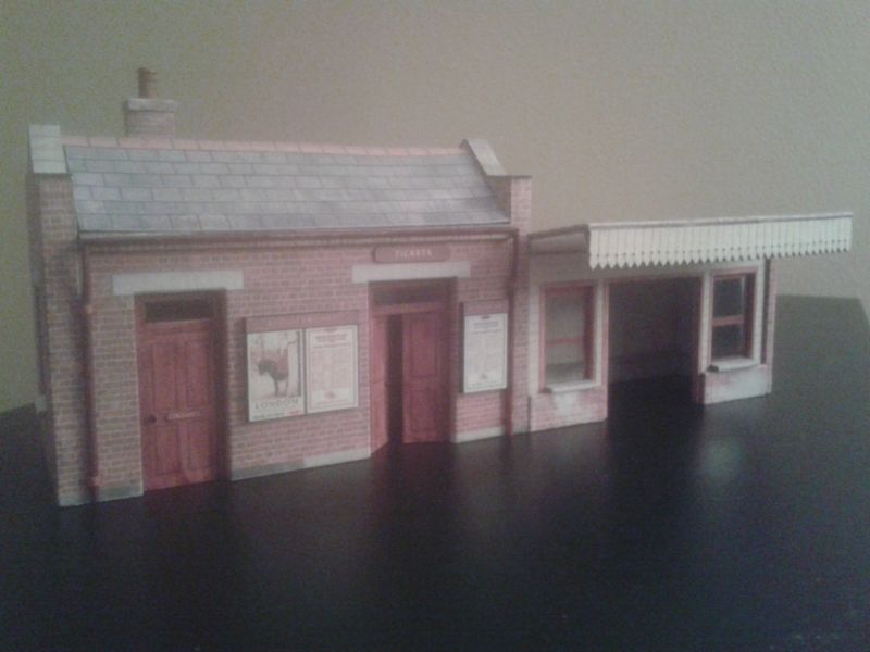
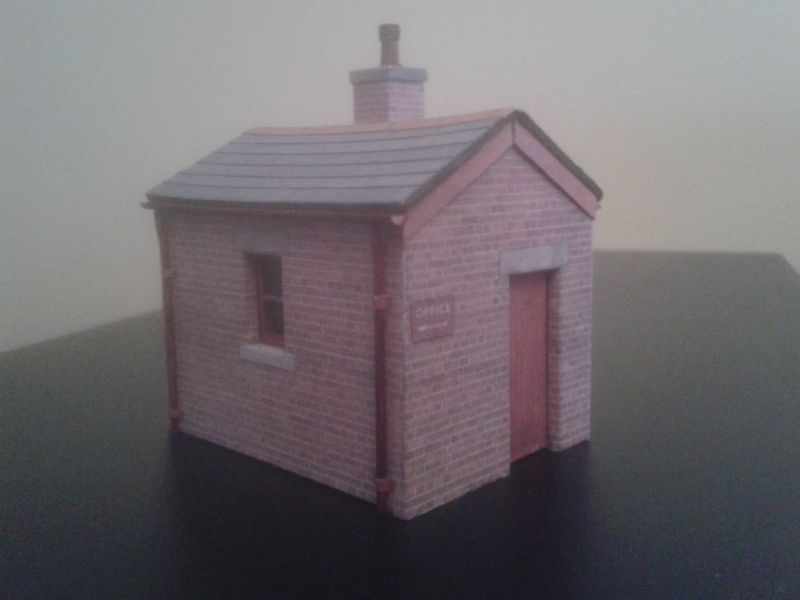
I shall be making use of Scalescenes' buildings or scratchbuilt buildings utilising Scalescenes' brick papers. The Scalescenes' Small Station Building is ideal for this layout and, as mentioned briefly in another thread, I have already built this with some slight alterations. Apologies if you have already seen this picture, but for the sake of completeness here it is again…
The Scalescenes' Weighbridge Office is nearing completion. As regards the goods shed, I have come across a drawing of an LMS type previously situated at Eckington and I'm tempted to scratchbuild it.
More as and when things develop.
Regards to all.
Terry
Last edit: by Barchester
Posted

Full Member
Best,
Bill
At 6'4'', Bill is a tall chap, then again, when horizontal he is rather long and people often used to trip over him! . . . and so a nickname was born :)
Posted

Full Member
Nice challenge. Some of the articles on small and even large layouts from the previous century were somewhat optimistic. Looking at one from 1974 right now. And scratching my head. Definitely one from the armchair. As the author candidly states.
6 feet by 1.25 feet - acres of space. :doublethumbGoforit. Are you doing the turntable?
Nigel
©Nigel C. Phillips
Posted

Full Member
Last edit: by GreenBR
Acording to a recent visit to a supermarket at check out time, I an not loosing my memory it has been downgraded which means i am not stupid afterall - Sorted! - What a relief
Posted

Site staff
Regards
Alan
Born beside the mighty GWR.
Alan
Born beside the mighty GWR.
Posted
Legacy Member
reg
Posted

Site staff
Ed
Posted
Full Member
Welcome aboard chaps. It won't be a fast build but I hope to make steady progress.
Ed. I decided that 'Midland in the round' wasn't doing it for me. The plan was a bit of a fudge from the start. I could see that it wouldn't hold my interest so all the buildings and most of the track was retrieved and the layout dismantled. Still, I now have a big pile of wood for future projects.
My current thoughts are that this current layout should be built with exhibiting in mind, but also consideration be given to extending it in both directions to make a through station. It could then form the basis of another layout around the shed, possibly with another station on the other side of the shed, maybe something a bit more industrialised.
On the other hand, this layout might be the first of a series of small exhibition layouts which will never be extended. However, the need to just run trains round and round could be satisfied by building a narrow non-scenic running track around the four walls of the shed. I am undecided at the moment.
Regards to all.
Terry
Last edit: by Barchester
Posted
Site staff
Ed
Posted

Full Member
It is a problem with magazines – they start repeating themselves every 40-years or so…The latest published attempt at 'the art of compromise' appeared in the October 2018 Railway Modeller by Chris Ford. Part of the original article was re-produced along with the original track plan. I was sufficiently intrigued to buy the magazine and decided at long last to slay this particular dragon and attempt to build it at last.
Looks like you've made a good start – I will look forward to seeing it progress!
Gordon
Posted
Full Member
I managed to solder the wiring to two of the four point motors yesterday. I also stuck them in place beneath the baseboard with a cheapo version of 'no nails' as intended.
The finishing touches have been added to the weighbridge office…
I shall wire the other two point motors later today and glue them in place. After that, the wiring will need to be attached to terminal blocks.
Terry
Last edit: by Barchester
Posted

Full Member
In the UK we have a substance called "Nemesis" which is available from building suppliers. Cheap and very very good. Apply it with a gun as per No Nails etc.
Barry
Shed dweller, Softie Southerner and Meglomaniac
Posted
Full Member
The SEEP point motors are installed. I haven't yet thought about a control panel so operating switches have been temporarily fitted to test the point motors and ensure that trains will run over all of the trackwork. Having never used point motors before, I am finding it quite novel to flick the switch and watch the blades spring over with a satisfying thud!
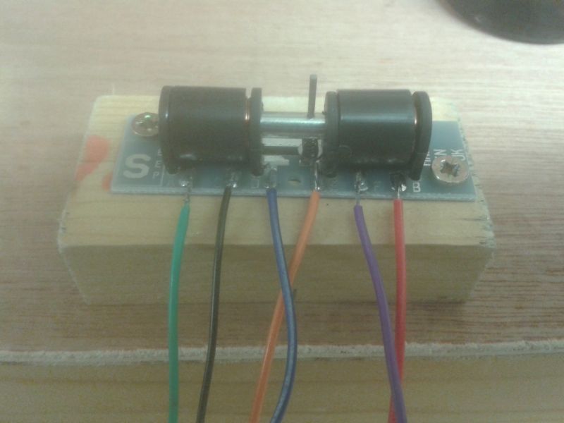
I was quite gleeful when, having wired and fitted the first point motor, it all worked perfectly. My glee was short lived however, as when testing the second point, the frog was completely dead, causing my test loco to come to a sudden halt. That particular point had been recovered from my previous layout building effort so I looked at some others from the same source to try to understand why power was not reaching the frog. I came across this…
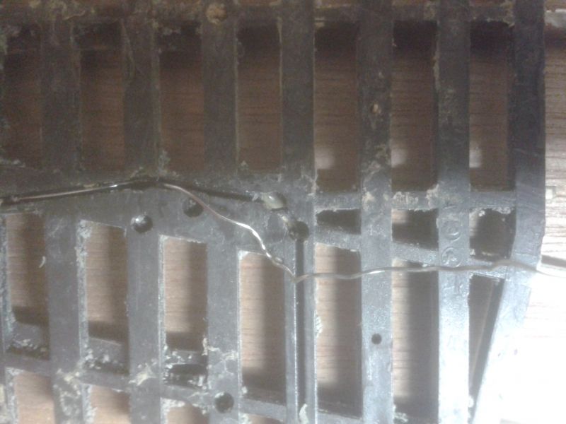
The two circular holes in the centre of the picture appear to contain metal contacts to which the thin wire had been previously soldered, thereby providing power to the frog. The wire obviously has become detached. I wondered if the same had happened to the point which was not working properly. I couldn't lift it to look underneath so I decided to take the bull by the horns and solder another wire from the side of one of the rails forming the frog, and connect it to the appropriate terminal at the relevant choc block. Deep joy! Power was restored.
The project grinds slowly forward.
Terry
Last edit: by Barchester
Posted

Inactive Member
Cheers
Max
Port Elderley
Port Elderley
1 guest and 0 members have just viewed this.