Take a piece of board
Posted
#265212
(In Topic #14435)
Full Member
A small shunting layout
My loco fleet includes a small number of Bachmann classes 04 and 08 diesel shunters in either British Railways green or black. They have spent most of their lives in a cupboard instead of working for a living. Recently, whilst sorting through some wood in my shed, I came across a small piece of mdf measuring 41.5 inches by 12.5 inches. As always when presented with a small offcut of board, my mind begins to mull over the suitability of said board to form the basis of a model railway. I thought that it might be possible to build a 'quickie' shunting layout on which to run the aforementioned diesels, my aim being to use, as far as is possible, track and other items already in my possession.Planning model railway layouts is not a strong point of mine. I tend to start with a general idea of what I want and work from there. This often results in changes being made 'on the hoof' and the relisation that I have forgotten to include this or that, resulting in a 'one step forward and two steps back' approach.
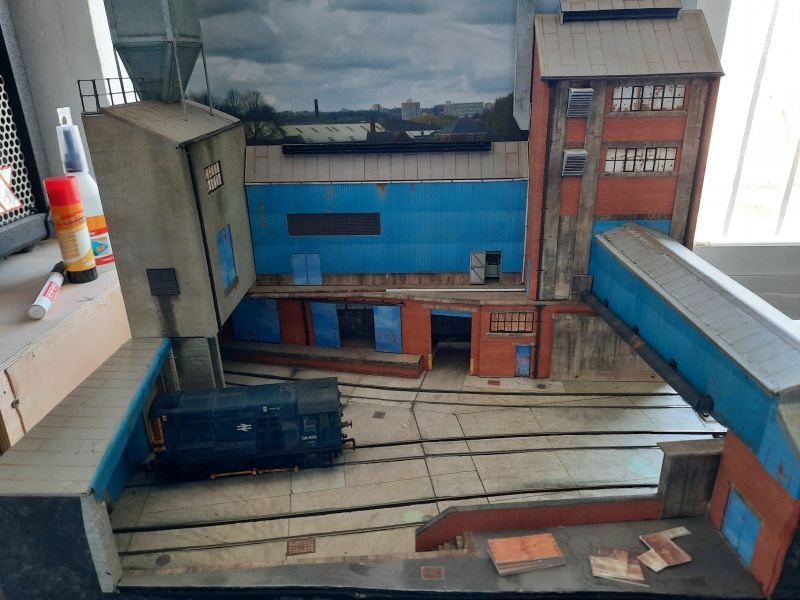
I have a vague idea of a suburban yard serving some light industries with factories or warehouses in abundance. These will be constructed from Scalescenes' kits and some may be scratchbuilt. I'll work this out as I proceed.
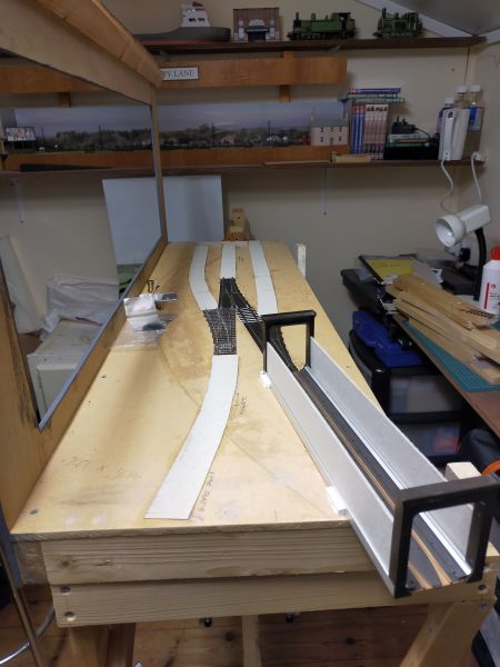
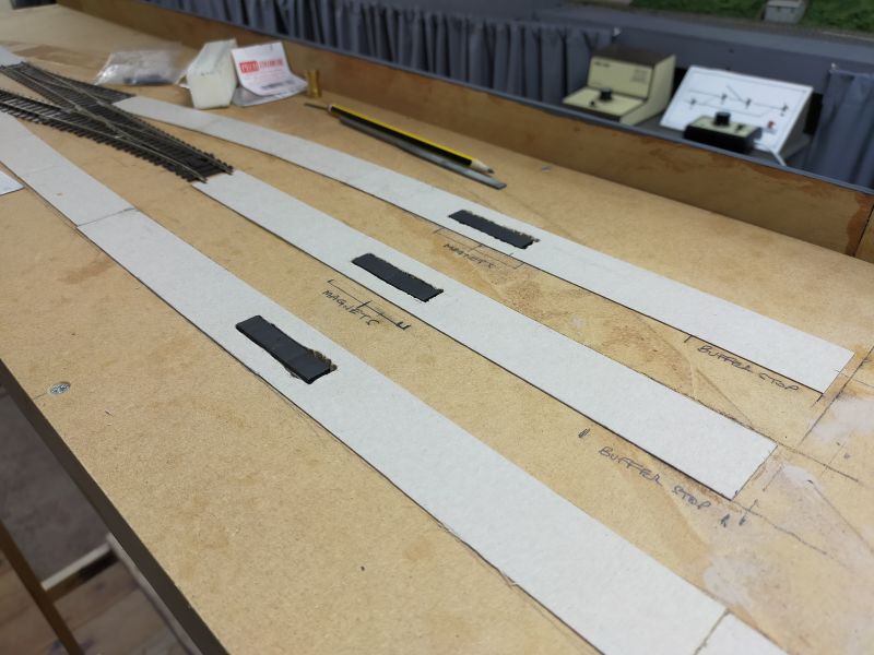
I have looked over the Peco code 75 flat-bottom points in my possession and have selected three medium points. Plain track will be C&L code 75 bullhead. The C&L track has thinner sleepers than the Peco points so in order to bring the rail tops into alignment, 32mm wide strips of cereal packet card have been glued on the baseboard to which the plain track will be pinned with Peco track pins.
I have two unused Peco SL-43 Loco Lifts and these will be pushed into service singly to act as removable fiddle yards. Each one is capable of holding one class 08 and two wagons or vans.
Here is a general view along the layout with the loco-lift on the bottom right hand corner. This is located on the baseboard by small pieces of Evergreen styrene strip (see next photo). The two left-hand sidings will end at buffer stops and the right hand road will pass through a building and onto a fiddle-stick suspended at the far end of the layout. There is a headshunt on the left foreground for the left-hand distant siding.
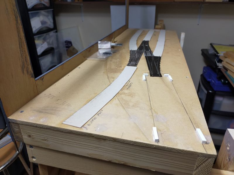
A similar view showing the pieces of Evergreen styrene strip used to locate the Peco loco-lift.
More soon.
Terry

Posted
Full Member
The box file 'kit' went together well and I added some extra bits like railings and legs on the hopper area.
Good luck with your new venture.
Gary
Gary
__________________________________________________
I am no expert but I do what I can, when I can, with what I can.
__________________________________________________
I am no expert but I do what I can, when I can, with what I can.
Posted

Full Member
Looks very interesting!
Awaiting further developments
Barry
Shed dweller, Softie Southerner and Meglomaniac
Posted
Full Member
Terry
Posted
Full Member
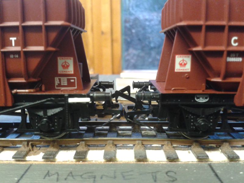
I use two bar magnets, end to end, which gives sufficient length for both couplings on adjoining wagons to lift at the same time.
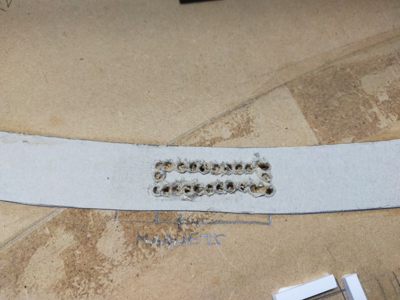
I decided to place magnets at the end of all tracks and rectangles were drawn and then cut through the baseboard and cleaned up with files. Basically, I drilled a number of holes around each drawn rectangle and joined the holes using a small saw.
Next, a small piece of mdf was attached beneath the hole using a strong adhesive. In this case I used the £1 shop version of 'No Nails' which always seems to work well for this type of job…
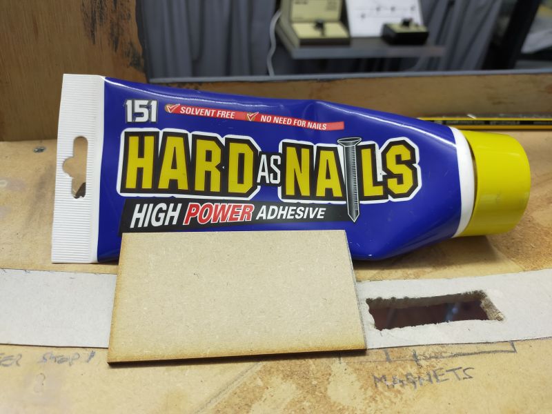
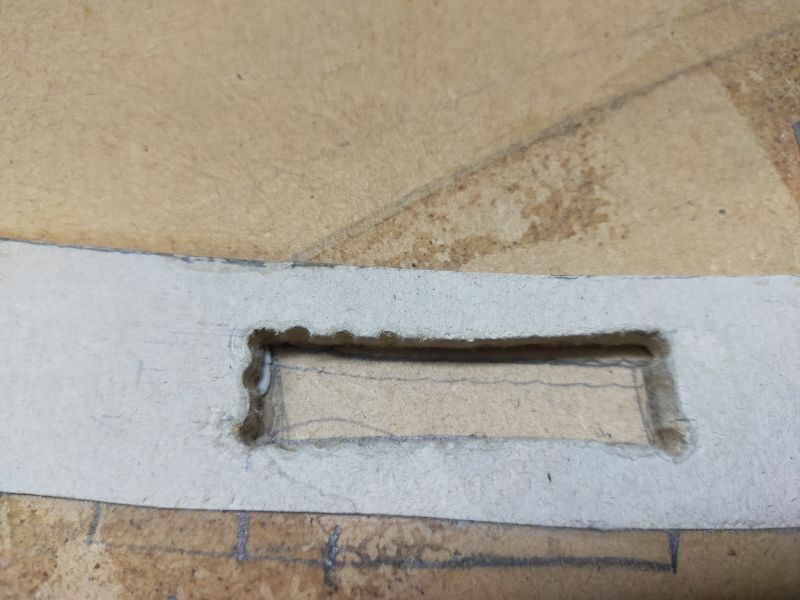
The bar magnets are 3mm thick and the depth of the hole is 7mm, therefore I glued two lengths of 2mm greyboard into the hole to bring the top of the magnets up to the same height as the trackbed…

The gap around the magnets will be filled with ready-mixed plaster and the track will be laid directly over the magnets. The sleeper depth of the C&L track being used is only about 1mm, and experience with my other layout Farleigh shows that the magnetism is not reduced in any way.
All magnets have been fixed in place…
I mentioned in the first post about working things out as I went along and the magnets nearer the camera on the view above are an example of this. I decided that it might be useful to have the ability to deposit a wagon at that location. No matter if those particular magnets are never used but it is far easier to install them now with the possibility that they might be used, rather than fitting them retrospectively once the track is laid. How do I know? Read through my Farleigh thread to find out!
I also mentioned above that the plain track would be pinned down. I remember that rather nice evenly ballasted track was obtained on my small layout Poppy Lane (see: A 'watching the trains go by' plank) by gluing down the track and covering with ballast at the same time. I am inclined to try this method again - anything which speeds up the dreaded chore of ballasting track.
More soon.
Terry
 Last edit: by col.stephens
Posted
Full Member
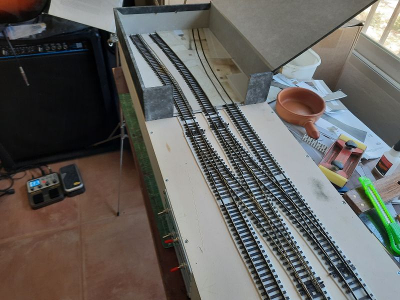
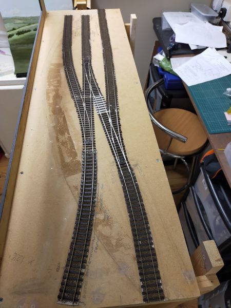
I also decided that the Peco loco-lifts would intrude too much into the scene so have extended the track to the edge of the baseboard. The idea is now to attach a removable fiddle-stick so stock changes will take place beyond the scenic area. This is where we are at present:
I have also been experimenting with the means of switching the turnouts. I decided that wire-in-tube would be ideal. I wasn't quite sure how switching the polarity of the common crossing (frog) would be achieved but decided that micro-switches would be the way to go. I haven't used these before but they are very cheap and I wanted to improve my knowledge of how these things work with regard to model railways. How to insert the micro-switch into the linkage between the lever and the tiebar was a conundrum. I gave the matter some thought and came up with the following solution. I'm sure this method has been done countless times before by numerous people so I have no plans to patent it!
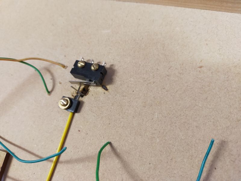
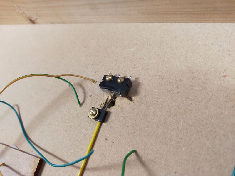
As per usual, the wire is bent at a right angle beneath the Peco turnout and is pushed up through the slot previously cut into the baseboard, to engage in the hole in the tiebar. However, before doing this a small length of wire is soldered to the upright, protruding downwards away from the tiebar. In the photo below the right-hand wire is destined for the tiebar and the wire heading left will protrude downwards. It will be trimmed to length once in place.
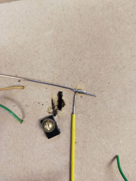
The upright wire is fixed in place through the hole in the tiebar. In this case the black clip above was also fixed over the yellow tube to hold it in place. A micro-switch was placed on the far side of the slot in the baseboard and was held in place whilst the wire-in-tube was activated to throw the turnout. The downward facing wire pushed against the lever of the micro-switch and this enabled me to establish exactly where it should be located. After the micro-switch was screwed into place, the wire was trimmed. These two photos should make it all clear. The micro-switch is yet to have wires attached.
Here is one of the three levers which I will be using to throw the turnouts…
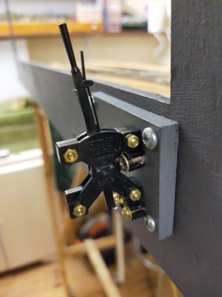
The levers, wire and tube and associated bits and bobs were retrieved from a previous abandoned project. They were bought some years ago from a one-man company in America which is no longer trading as far as I can ascertain.
More soon.
Terry
Last edit: by col.stephens
Posted
Full Member
That lever looks gorgeous!! I can see why you went wire-in-tube with that on the end of the wire

Barry
Shed dweller, Softie Southerner and Meglomaniac
Posted

Full Member
Looking forward to the next chapter. :thumbs
'Petermac
Posted
Full Member
The lever and associated fittings are made from plastic and came on a sprue. If I remember correctly you got two levers per sprue. The wire, tube, screws, nuts and bolts were all included in the kit. The company went under the strange name of 'Hump Yard Purveyance'. It's a shame that the company appears to have ceased trading.
I now have to fit the other two levers in place, sort out the other two micro-switches and then connect the electrical wiring. Then we will see if it all actually works.
Oh, and no pressure, but I have offered to exhibit this layout at my club show in May 2023. Best get my finger out, as The Duke of Edinburgh used to say (may he rest in peace).
Terry
Last edit: by col.stephens
Posted
Full Member
"Houston, we have a problem!" When tested, the point nearest the front of the baseboard, a Peco medium left-hand point, will allow a loco to travel straight over the crossing (frog), but when the point is thrown to the diverging road the loco stalls on the common crossing (frog). I have changed the micro-switch just in case it was faulty but the problem remains. This particular point was retrieved from a previous project and was damaged at the end just before the end of the blades. The end of the curved rail had become detached from the fixings on the sleepers. I am wondering if this might have something to do with the problem but I cant really see why it should.
In the absence of any bright ideas I fear that the only way forward is to lift the point and replace it with a new one.
Any suggestions would be welcome. Thanks.
Terry
Posted
Full Member
You say the point was damaged earlier so it is possible that the gap between running rails and frog are tighter than they ought to be ……… :hmm
Having said that, being Code 75, the points are probably electrofrog so contact at the frog shouldn't make any difference. Presumably you've used insulated joiners and removed the wire link underneath (does that exist on Code 75 electros ?)
A stray strand of wire maybe …………track pin…….. ???
'Petermac
Posted
Full Member
Terry
Posted
Full Member
Terry
Posted
Full Member
Forgive me if this is teaching your Grandmother etc…….
It is advisable to loop a wire between the stock rails and the point blades to avoid having to rely on the contact of the blade to transfer the current. I presume you have done this? I didn't bother on my very first layout and paid the price with poor running.
Just a thought….
Shed dweller, Softie Southerner and Meglomaniac
Posted
Full Member
I'm slightly annoyed at having to buy a new point as the aim was to use existing track already in my possession.
Terry
Last edit: by col.stephens
Posted
Full Member
Robberdoc
Posted
Full Member
Terry
Posted
Full Member
Terry
Posted

Full Member
I thought of you just a few days ago Terry, when sifting through some storage boxes in an outbuilding and found my package from the 'Hump Yard Purveyance' from some years back. They are a neat WIT system and I have enough parts for a small plank when the inspiration arrives and they're wonderfully tactile and so much more economical than Tortoise motors!
Best,
Bill
At 6'4'', Bill is a tall chap, then again, when horizontal he is rather long and people often used to trip over him! . . . and so a nickname was born :)
1 guest and 0 members have just viewed this.