Kevin's Inglenook Junction

Post

Posted
Rating:
#242681 (In Topic #13411)
Avatar
Full Member

Two Planks Become One

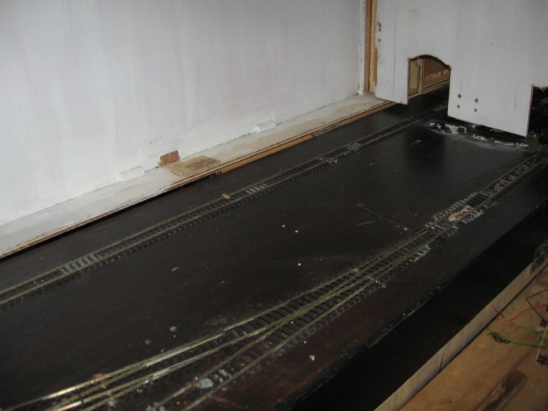
At Long Last Some Photos, my original Inglenook now has an extension? to get some more operating space. Meanwhile doesn’t that scenic break look bare, this is the non scenic back side of it. And the scenic side isn’t any better, just two portals stuck on, and there is a lot to do. But at the time of writing, I am losing the will , I need inspiration, and lots of it. Originally the scenic break wasn’t a scenic break at all, but just a support for the lid, it only became a scenic break when I added the extension. It would seem that I cannot finish one job before I start another one. Best wishes Kevin 


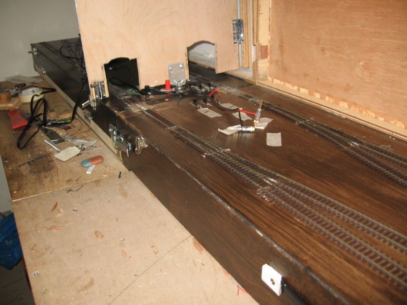
More Later (Hopefully)

Kevin

Last edit: by Passed Driver


Staying on the thread Kevin.
Online now: No Back to the top

Post

Posted
Rating:
#242685
Avatar
Legacy Member
Looks like you are making some positive progress the Kevin
The upright board between the 2 planks is that a scenic break or is one plank a fiddleyard?

Brian

OO gauge DCC ECOS Itrain 4 computer control system
Online now: No Back to the top

Post

Posted
Rating:
#242686
Avatar
Full Member
Hi Brian. Thank you. It is a scenic break between the Shunting Puzzle and the fiddleyard. I have a pair of tunnel portals to glue on. The Inglenook has been working successfully  for three years and I was too busy Shunting back and forth to bother with scenery. But it all came to a shuddering halt ( shuddering halt ,was somewhere in Kent?) with the series of short circuits.Best wishes Kevin 

Staying on the thread Kevin.
Online now: No Back to the top

Post

Posted
Rating:
#242688
Avatar
Legacy Member
I believe Nigel is working closely with you re the shorts so i wont complicate issues im sure it will be something simple thou now with you posting pictures it will help a great deal in resolving problems.


Brian

OO gauge DCC ECOS Itrain 4 computer control system
Online now: No Back to the top

Post

Posted
Rating:
#242692
Avatar
Full Member
Hi Brian. Thank you for your reply. The thing is that being the third plank/ module that I have knocked out, all with the points wired the same way, being, three wires, (one from the bus, one from the DPDT Slide switch, and  one stock rail of the point) soldered and Insulated together, have worked, apart from the odd hiccup .Best wishes Kevin 

Staying on the thread Kevin.
Online now: No Back to the top

Post

Posted
Rating:
#242695
Avatar
Full Member
Great to see some photos Kevin, and progress being made.   The dark art of electronics is frequently a mystery to me too, so I feel your frustration!  Nice looking carpentry though….

You actually have a nice amount of space for scenery and buildings - your planks are not as small as you may imagine - plenty of room for some interesting cameo scenes a la John Dew, I think…. And as you have backboards in place for a backscene, lots of opportunities to give the track a location.  And room for low relief buildings too.  Very exciting.  

I saw a layout along similar lines to yours.  They had material, a little like curtains, behind tunnels portals that led to a fiddle yard.  The locos could push through it, but once through, the "curtain" stopped a viewer seeing through the tunnels and into the off scene work - you might want to  consider something similar.  

Keep us up to date!

Michael
Online now: No Back to the top

Post

Posted
Rating:
#242698
Avatar
Full Member
Hi Michael. Thank you for your reply. I have been trying to figure out just how to do that, that being like a valve. Meaning to say that when the Loco enters the tunnel from the scenic part of the layout it will just move the curtain out of the way, whereas on the return journey it could become snagged. I was thinking along the lines of a flexible rubber tube.  Best wishes Kevin 

Staying on the thread Kevin.
Online now: No Back to the top

Post

Posted
Rating:
#242699
Online now: No Back to the top

Post

Posted
Rating:
#242701
Avatar
Full Member
Hi Michael  Thank you for your reply.   I will take that on board.  Best wishes Kevin 

Staying on the thread Kevin.
Online now: No Back to the top

Post

Posted
Rating:
#242702
Avatar
Full Member
Hi Michael. I have been studying your suggested tip, about the tunnel and beyond. My pair of portals by Noch, are made from “ Hard Foam “ , which looks good, now for the tunnel lining, I purchased a sheet on O gauge stone which would be fine if the sheets were larger? Then, but I think brick would look more authentic, the sheets could be set diagonal, the way that tunnel linings are laid. Have you got any comments? Best wishes Kevin 

Staying on the thread Kevin.
Online now: No Back to the top

Post

Posted
Rating:
#242703
Avatar
Full Member
Wow Kevin - what a difference a photo makes !!  We can now see exactly what you're talking about and, as Michael said, you have a pretty decent space there to make a very appealing "shelf" layout with lots of operating potential.

I also think his idea of a curtain hiding the fiddle yard is good.  Light "flimsy" material is the one to go for, not heavy tapestry type stuff.  It won't snag when the stock exits the fiddle yard if you design it like a walk through fly screen - i.e. 2 flaps with a split down the middle.

Great stuff - keep the photos coming now you've discovered how to do it.,

'Petermac
Online now: No Back to the top

Post

Posted
Rating:
#242707
Avatar
Full Member
Hi Petermac. Thank you for your reply. You are correct about “ light at the end of the tunnel? “, but the total length including the fiddleyard is only eight feet ( 2. 4384 ) . As for photos, I have to get out of the rut of playing trains instead of building scenery.    Best wishes Kevin 

Staying on the thread Kevin.
Online now: No Back to the top

Post

Posted
Rating:
#242743
Avatar
Full Member
Hi Petermac.  Yet another reply ? WOW? Yes but the gremlins are about again. I stripped all the wiring from the fiddleyard, and I do hate waste, except for the frog wires and bus. Then I began again red droppers to the red bus likewise black droppers to the black bus, straight forward, then wire the DPDT Slide switches to their respective buses “ simples” . Connect power and detect a short, even without a Loco on the track. I had better get out the Multimeter.  Best wishes Kevin 

Staying on the thread Kevin.
Online now: No Back to the top

Post

Posted
Rating:
#242746
Avatar
Full Member
You have a nice little plank there Kevin. It's good to finally see it
Online now: No Back to the top

Post

Posted
Rating:
#242748
Avatar
Site staff
Barchester is in the usergroup ‘Super-moderators’
Kevin if your going to strip and re wire I would suggest connecting two wires, one to each rail then test, if ok connect next two in line and test, slowly work through the plank until fault appears, hopefully this will show where fault is occurring
Cheers

Matt


Wasnie me, a big boy did it and ran away

"Why did you volunteer ? I didn't Sir, the other three stepped backwards"
Online now: No Back to the top

Post

Posted
Rating:
#242749
Avatar
Full Member
Hi Zelda. Thank you for your reply. But it is a PITA about the gremlins and the short circuit. Best wishes Kevin 

Staying on the thread Kevin.
Online now: No Back to the top

Post

Posted
Rating:
#242750
Avatar
Full Member
Hi Matt. Thank you. I should have got your advice earlier, as I have already begun the job. Best wishes Kevin 

Staying on the thread Kevin.
Online now: No Back to the top

Post

Posted
Rating:
#242753
Avatar
Full Member
Hi Kevin,

Matt is spot on, but with a multimeter you not need current going to the rails. If you have continuity in ohm mode with the contacts touching the rails you have a short. If you used rail joiners and the track is not gapped between sections you may need to start from scratch. Check any copper clad sleepers to make sure the sides are isolated, and check that the frogs are in fact electrically isolated from the closure and exit rails. Did you do a full conversion of the points or are they still power routed? Check the point rails are in fact isolated from each other.

Nice to see some photos. Re the "tunnels": Do just that. You have space for what looks like 4"-6" of tunnel painted black or brick wall cuttings inside on the fiddle side, scenic the track for another foot with ballast and perhaps some backdrop buildings and it will look fine. Use some cutouts and the camera to see where you need to put them. All this depends on the viewing height. Standing at the far end of the scenic plank and looking through at viewing height will determine how far so you need to go. Bits of paper or strips of plastic hanging down will end up in the rods or wheels at some point. Usually with undesirable results.

Remember my comment some time ago about angling the fiddle yard entry/exit track?

Nigel

©Nigel C. Phillips
Online now: No Back to the top

Post

Posted
Rating:
#242758
Avatar
Full Member
Hi Nigel. Thank you for your reply. When I read Matt’s comments, I worked in reverse, and have been de soldering all the bus connections.,    :off topic now I have taken a dinner break ( spaghetti bolognaise ) plus tea and biscuits.Yes I did “a full conversion on the Electrofrog points “. As for cuttings, a nice idea, but I haven’t got much headroom on the fiddleyard board unless they were either flexible or removable? I haven’t got my head around Multimeters yet.
Re the cut outs , is that from Magazines? or whatever. It was good of Matt to sort out my laptop for me, and I have still got to purchase a mouse mat.   Best wishes Kevin 

Staying on the thread Kevin.
Online now: No Back to the top

Post

Posted
Rating:
#242760
Avatar
Full Member
Hi Nigel.  Another reply ? I will have to find a better title for my thread. The Bodgit was a reference to the haphazardly way that I added/ changed use of the programme track., “Inglenook Junction “ would sound better.  Best wishes Kevin 

Staying on the thread Kevin.
Online now: No Back to the top
1 guest and 0 members have just viewed this.