Automatic Signal Control
Posted
#28085
(In Topic #1954)
Guest user
Ok here we go then…….
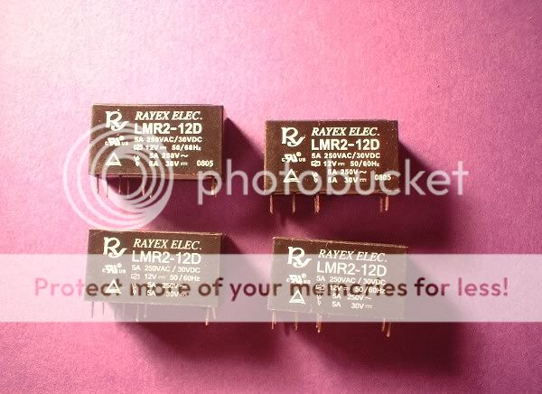
My signaling system uses standard 12vDC double pole changeover (DPCO) relays that were obtained off the shelf at Maplin electronics. For those who are wanting to build this module for their own layouts the Maplin part number is N31AW. For this example I have used four relays as they will be operating a four aspect signal. Each relay is in effect one block section and is triggered via a reed switch mounted between the rails. This basic design can be altered by adding or removing relays as required depending on how many block sections you require.
Here are the relays as supplied…….
The first job is to fix the relays together. For this I used some tape……..

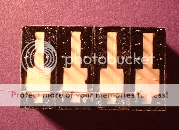
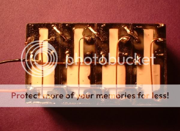
Before we go any further take a look at the position of the pins. The two pins at the bottom of the relays are for the operating coil. The pins at the top are arranged in two rows of three. The middle pin of the three is the common whilst the pins either side are the normally closed (NC) and normally open (NO) connections. The NO is right at the top, the NC under the common. Each relay has two sets of these switches,one on the left and one on the right.
For wiring up the module I used some bare copper wire. First we add the common for the operating coils…….
This is done by carefully bending down one of the pins then soldering it to a length of copper wire that is lying on the base of the relay. Next we add the common for the switches exactly the same way………….
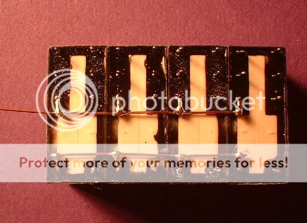
Note that this common wire connects the NC pin only on one side of each relay. This connection is what breaks the supply to each relay in turn.Now we start to get complicated…….

Carefully bend over the pins shown in the pic above and solder them together. Next we join the end relays together like so…….
This was only connected like this to show where the wires go in reality it would look like this ……….

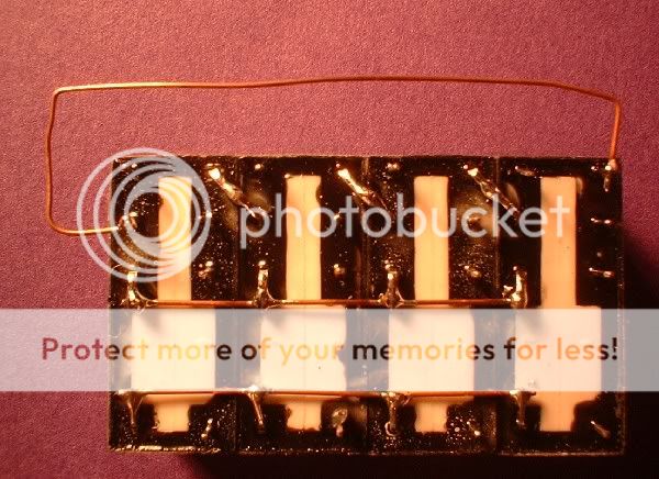
Now we add the most important links. These links are where everything else attaches to………..

From the last pic it is possible to see how the circuit works. Make sure however that these links are positioned higher than the others to prevent a short circuit as seen here in this side view…….

And that as they say is it! Now we need to wire the module to the layout. First we add the power connections. I have used red for the +ve and black for the -ve…….
Now the wiring of the above is down to personal preference. I prefer to switch the -ve side of the relays so from now on this is how the module is wired. If you prefer to switch the +ve then swap the supply wires round. Next here's how to wire in the reed switches…….
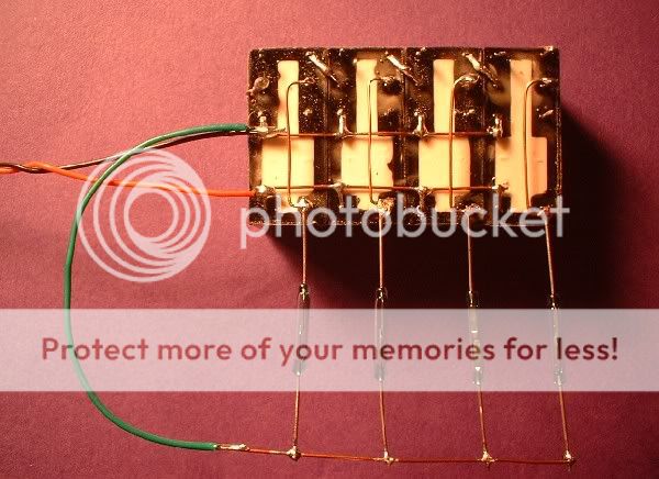
One end of the reed switches are connected together whilst the other ends connect to the control links on the module. In reality the reeds would be mounted between the rails and connected to the module via cable. Now we need to add a signal. In true blue peter style"here's one I made earlier!"…….

As the signaling system is destined for installation outdoors the signals are having to be build with ease of installation in mind. With an indoor layout the wiring goes under the baseboard outdoors on a concrete trackbed you have to think differently. My signals are all scratch built using 1.8mm led's and plastistrut( see other thread). All the led's are wired common +ve so each signal only uses one current limiting resistor for all the led's. This can be carefully mounted in the signal post if there's enough room. The signals all use six core alarm cable wired as follows…. Red - red aspect, Green - green aspect, Yellow - yellow aspect, Blue - second yellow aspect, White - 12+ve and Black -ve. The black as can be seen in the above picture goes straight to the reed with the other side of the switch wired to the red aspect. More on this later. Here's how they wire to the module…..
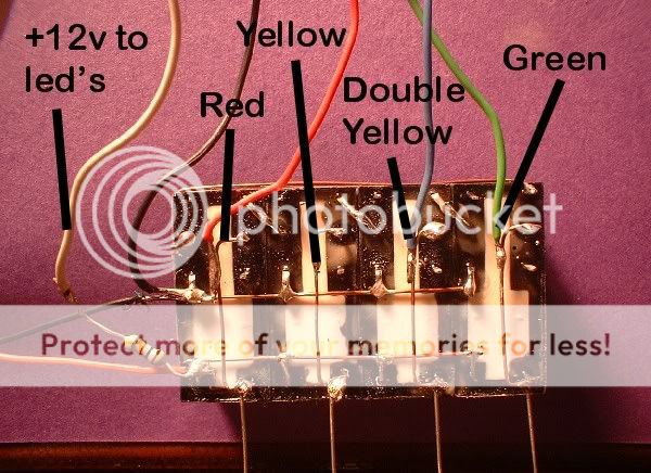
Note that the leds are connected to the same links as the reed switches. Now the module works from left to right so we start with red then the next is yellow then double yellow then green. However to get the double yellow aspect we need to change the circuit slightly like this………
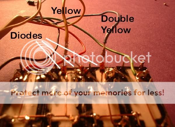
Note now how both yellow leds are fed via some diodes. The single yellow is connected to both the second and third relays using two diodes. The second yellow has to be connected via a diode also as if it isn't the first yellow will go out. For those eagle eyed on here note that the pic previous to the one above I had connected the second yellow without the diode at first before I remembered how to do it.
Now that we have connected the first signal the rest are connected exactly the same way the only difference is the the red will be connected to the second relay the yellow to the third etc etc. Now the really clever part of this design is its installation out on the layout. The module will be mounted in a box on the fence. A six core alarm cable will then be fed from it to a junction box further up the garden. The cable will connect to the +ve and -ve and each control link with the diodes for the signals mounted remotely in the junction boxes. Each signal will then 'tap' into this six core cable as it runs the length of the line. As mentioned earlier the reed switch for each signal is wired in common with the red aspect. Now to be really 'flash' the same six core cable will also be used to provide train position on a diagram by the control position. By wiring another relay coil in parallel with any on the module you can switch the track supply on/off. The possibilities are endless from one small module. Like I said at the beginning you can have as many relays as needed as long as there's a minimum of two and you can drive two, three and or aspect signals as required. After I built the module it was tested first with a length of wire then using a magnet on the switches. Once I have posted this I will upload two short video clips. I hope this will inspire some of you to experiment with automatic signaling and automated control. Good luck!! Dave.:thumbs
Just as an after thought the relays used (N31AW) were £1.80 each from maplins. The diodes are just small switching diodes mine were out of my junk box. The diodes will have to be connected the other way round if you are switching the +ve instead of the -ve as I have. And finally and most importantly……
When first powering this module up nothing happens until the first relay is activated.
Posted
Guest user
First I triggered the relays using a wire link……..

Second we triggered the relays using a small magnet on the end of a screwdriver……..

Posted
Guest user
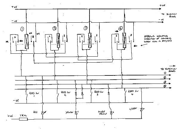
Each relay has two sets of contacts. For ease of drawing the diagram I have put these either side of the relay coil and marked them A and B. Note when the coil is energised the contacts move in the direction of the arrows.
You will notice that I have brought all the control link connections down to a set of four lines in the middle of the diagram. These represent the cables that run out to the junction boxes. The +ve and -ve also also run out to the boxes although I have included them at the bottom of the diagram to show how the switches and leds are connected. I have shown all four reed switches but the leds only relate to one four aspect signal. The rest of the signals are wired the same the only difference is the way they connect to the four 'bus' lines. The easiest way to wire them is to remember that the red always wires to the same 'line' as the corresponding reed switch.
1 guest and 0 members have just viewed this.