Building a Signal Bridge
Posted
#30590
(In Topic #2059)

Inactive Member
"Kitch Buildbashing"
Behind a row of hills, is the Salt Creek bypass, a pair of overtaking loops in the double track. To run past a train, it has to be parked in a loop and then the turnouts changed to the other line. This operation is done via CCTV. To see where the locos are stopping needs a reference point. I thought a simple signal bridge at each end, would be just the thing.
For this signal bridge, you will need two Bachmann kits number 45134 and one Cornerstone caged ladder set number 933-2956

First step. Assemble the kits, but don't attach the walkways.

Cut the legs off one of the kits and cement the two together. There may be some filing required to get the two to match. Then cut the hand rails off one side. This will allow easy access for your soldering iron.

Drill holes in the fish plates on the gantry and insert red/green LEDs so that the legs pair up with those opposite. Cut the legs off the LEDs and solder together.

Solder a 1k ohm resistor (for 14vDC) to each side of each pair of LEDs and a wire to each of the common legs (centre). Pull the two sets of three wires through to the rear supports and CA glue them to the posts.

A view from above showing the wiring, resistors and LEDs. The leds are wired together so that they operate as a pair of pairs for each bridge and when each LED is green, its partner is red and vice versa.

Next fit the walkways and hand rails. Assemble the caged ladder and attach it to the front end of the walkway.

Lay the bridge on its side and apply thick CA glue to the collar of each LED. Drop a 3/8" x 1/8" flat washer on to each led to form the frame of the signal lamp. Turn the bridge over and repeat the process for the other four LEDs.

Here is a close up shot of the detail so far.

Here is the bridge just back from the spray shop. I used short lengths of shrink tubing to mask the LEDs and a plastic bag to mask the wires.

Glue short lengths of brass tubing cut at 45 degrees with a Dremel, to make the lamp shields. Paint the shields and frames matt black. I made a 14v DC power supply (left of picture) from a toroidal transformer and bridge rectifier, for testing LEDs. Hook the bridge up to the power supply for a final test.

Here is the bridge installed on the eastern end of the bypass. The wires go through the concrete footings and drop down through the base board on the end nearest to the hill.

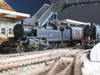
Here is a shot of the bypass, showing both bridges. The freight train is still "in the hole" waiting for the passenger train to pass. Note the red and green signals for that pair of tracks. The signals are connected to the turnout motors and indicate the clear path for each pair of turnouts at that end.

A close up of the bridge, again looking west, showing more detail of the construction.

and finally, looking east towards the bridge and cutting at Cripple Creek.
Max
Port Elderley
Port Elderley

Posted
Guest user
really good.
:thumbs;-)
 :cool:
Posted

Full Member
Wayne
Posted
Guest user
Posted
Full Member
Phill
Posted

Inactive Member
Ken.
'It don't mean a thing if it ain't got that Swing'
Posted
Full Member
Bob(K)
Posted
Full Member
Good job!!!
Cheers,John.B.
Posted
Inactive Member
Yes, Alan. I want to get some proto pics so I can copy the rusting on them and also on the girder bridge at Cripple Creek.I tend to knock things around a bit when I mount them, so the painting can be tidied up then. Let's just say that they have been recently installed . . .
Bob(K), the LEDs are three legged red/green which behave as though two LEDs have been built into one. The centre leg is common and the outside two are for red and green. One has a right angle bend at the top and the other is at 45 degrees. Two leg LEDs usually need a diode to change colours.
I can post the circuit if anyone is interested. Cheers Max
Max
Port Elderley
Port Elderley
Posted
Guest user
3 legged as you say - a simple changeover switch to power either leg. 2 -legs needs a full reversing switch as they require a complete reversal of power.
I have used both types depending on the circuit: 3 legs for signals: 2 legs connected across diodes being in series with output of track power under analogue control indicates if a loco motor is present. (If anyone in analogue wants a copy of the circuit, PM me with their e-mail address.)
Now Max, the next step is to have the signals change automatically as trains go under the gantry so that Red means that either the track is not set for exit at the far end or the track already has a train in it.
Posted
Inactive Member
The signals display the orientation of the turnouts, not the presence of a loco in the block. As you can see, the other bypass has no train, but the signals are still showing the orientation of the turnouts which feed the two tracks at each end.
Cheers. Max
Max
Port Elderley
Port Elderley
Posted
Guest user
2legged LEDs with DCC AC - I will test that a bit later today.
Posted
Inactive Member
Max
Port Elderley
Port Elderley
Posted

Legacy Member
1 guest and 0 members have just viewed this.