004.0 Blocks........... Occupancy Detection
Posted
#100161
(In Topic #5322)

Full Member
How to set up blocks and contact indicatoors
PLEASE POST COMMENTS/QUESTIONS IN THE MAIN RR&Co SUB FORUM
Blocks and Occupancy lndicators are inextricably intertwined so this section bounces back and forth between the two
BLOCKS
Just like the prototype, Blocks are the bedrock of train control (TC) with RR&Co. It is important that you fully understand their importance. A little time spent in the planning stage will save a lot of anguish once the track is laid and wired up.
In RR&Co a block is an electrically isolated section of track. The section should be uninterrupted ie no points.
Each block must be connected to some form of occupancy detection,
Reliable occupancy detection is a pre requisite of effective computor control. There are a number of alternatives available….. sensors operated by reeds and magnets or infra red which are switched on by the loco passing over them or occupancy detectors which are activated by the current draw on a section of track.
I read the RR&Co manual which has an excellent section on the pros and cons before deciding to go with contact indicators. I use Lenz LB101s hooked up to Lenz LR101 Decoders each of which serves 8 detectors. I have found them excellent.
Three sensors are required for each block. With version 7.0 only one contact indicator is required for each block, although earlier versions of TC required more.
This tutorial assumes the reader will be using contact indicators.
CONTACT INDICATORS
A contact indicator immediately detects if there is any current draw on the isolated section (block) to which it is connected.Even if the locomotive is stationary the contact indicator will detect its presence.
The moment the current carrying wheels of a loco enter a block, the locos presence will be detected and the block will be shown as occupied. Similarly the moment the indicator fails to detect any current the block will be shown as unoccupied.
There is a caveat here which, even at this early stage, you should store away at the back of your mind. The contact indicator detects current draw……not the source of the draw……it does not detect the loco identity nor does it detect that there could be more than one source of the current draw.
The use of contact indicators is not confined to blocks, although that is their primary use. You could, for example use an indicator to detect to determine occupancy on a fan of points. For now we are ging to focus on the use of a contact indicator within each block.
To move a train automatically in TC it has to start in one block (the specified start block) and finish in another different block (the specified destination block). This movement from one specified block to another is called a schedule. . One of the fundamentals of TC is you cannot have a schedule with only one block. I mention this now because you need to be aware of this when determining the number and length of blocks on your layout.
Determining the length of a block is critical. (for greater certainty the length of each isolated section). It is usually argued that a block should never be shorter than the longest train you are going to operate. I am not sure if this always has to be the case……certainly you need blocks where long trains can be safely stopped…… but to do automatic manoevres like uncoupling and loco run arounds I have found you need a number of strategically placed short blocks. We will discuss later the ways in which you can prevent long trains from being stopped in short blocks.
I have also found it is a false economy to dispense with blocks in sidings. If there is a remote possibility a loco will go into that siding there should be a block ,and therefore detector, there. You have no idea of the workarounds I had to adopt to shunt my coal siding because I "saved" money by not installing a detector and block:twisted:
You can set up indicators and blocks together or separately. In this example we will set them up separately because I want the indicator to be displayed on the switchboard.
SETTING UP A CONTACT INDICATOR
Select [TOOLS] from the main railroad menu

Alternatively you can select the indicator icon on the switchboard toolbar
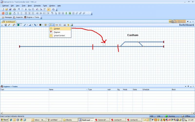
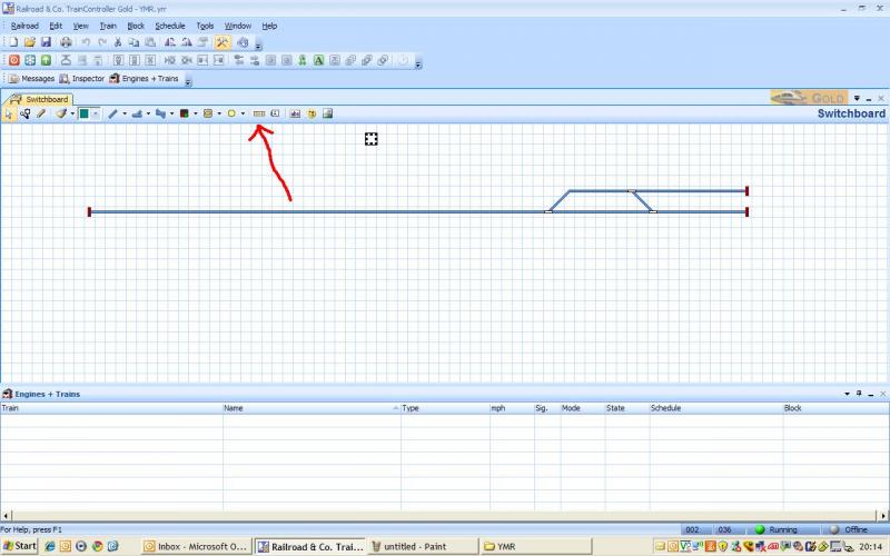
Click where the arrowhead is……….the red marks indicate the section is electrically isolated ie will become a block.
You should see a little black dot:

Note the little box shows the default address allocated by TC and that there is no connection….to remedy that….
Right click on the indicator and select [PROPERTIES] . This is a fairly standard TC properties box with tabs for
GENERAL CONNECTION OPERATIONS MEMORY and COMMENT
Select [CONNECTION]

Use the Digital System drop down menu to select the system you previously set up
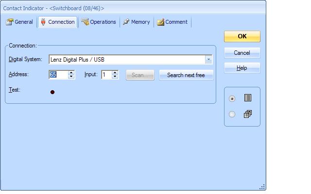
You will notice the window has changed….it may be different for other systems.
The address is the decoder number…….why 65? Lenz use the same numbering system for turnout decoders and accessory decoders and recommend that you leave numbers 1 thru 64 for turnout decoders and start your accessory decoders at 65
The input is the number from 1-8 of the detectors attached to that decoder.
If we were connected and you put a loco on the track section the dot next to "Test" would change colour to red as would the actual indicator we placed on the screen
For now select the Operations Icon (discussed in "Track Laying and Points") click on the dot and it will turn Red
Select the GENERAL tab
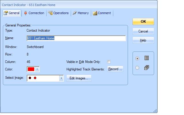
Although RR&Co automatically allocates a connection address (which you invariably have to change) it does not allocate a name. I have adopted a convention of joining the address and input together …651… and then some location name typically the name of the block that the indicator will be assigned to.
You can change the colours or image and only have the indicator visible in operations mode if it is activated. For now leave visible in Edit Mode unchecked.
For now we will ignore the other Contact Indicator tabs
SETTING UP A BLOCK
From the main Railroad Menu select [Tools] [Blocks]
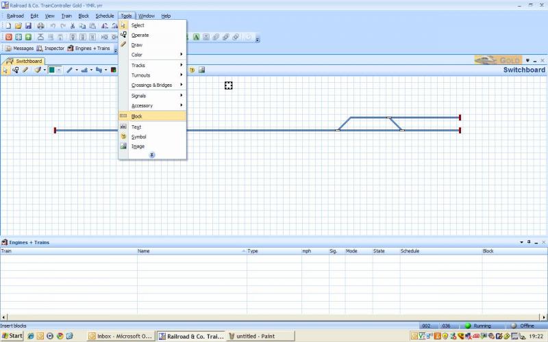
or select the Block icon from the Switchboard Tool Bar
Hopefully the two different methods of selecting items for set up are now self evident so going forward I will use text rather than screen shots for this type of selection
If you are worried about the absence of an indicator on this one shot…..dont. I took this shot before I decided to set up indicators before blocks
Click on the track roughly where you want the block to start and drag to the end of the block…….it should look like this
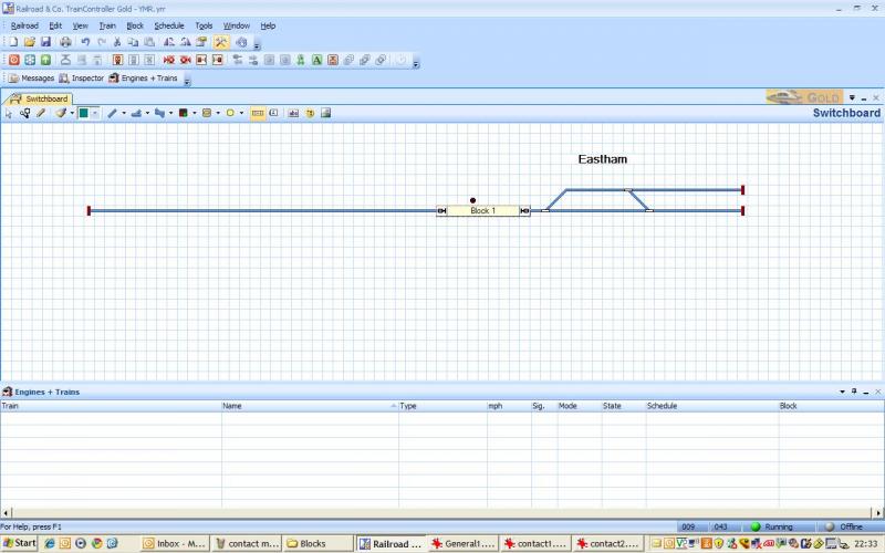
Note that TC automatically names/numbers the block and assigns signals at the start and finish
Right click on the block and select [PROPERTIES]
You will now be used to the TC property forms…….. select the [GENERAL] tab
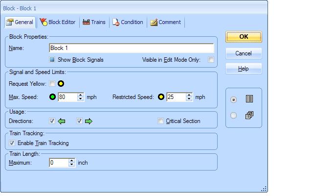
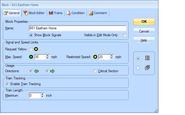
We will name the block to match the contact indicator we set up
We want to show block signals and for the purposes of this exercise we want the blocks to be visible at all times……later on you may want to change this
80mph is the default max speed……typically it needs reducing
If you uncheck one of the direction arrows ……trains can only go one way….this is a good idea on a double track mainline or perhaps storage sidings. There can be situations where there is more than one way to get from the start to the destination block…..the use of these blocks will speed up TCs decision making process
If you make this block a critical section TC will not permit entry unless it can also enter the next block. One of the ways of protecting long trains…..there are a number of other uses……a cool 7.0 innovation.
Enable Train Tracking by checking the box
The default train length is 0 or infinity……enter a smaller length if you wish to prevent schedules with long trains from using the block
The tab should finish up looking like this
Select
A block file is missing: (sources/blocks/.php or an overridden equivalent to this path)
Now we have to allocate a contact indicator to the block. Select the second icon [Insert an existing Indicator] there will be a drop down menu of unallocated indicators (an indicator can only be allocated once)

select the indicator and click on the block and it should look like this
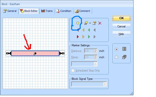
Pink means an indicator is allocated. The blue border means you are in edit mode……If you dont see the blue border it means you havent clicked on the block and all the icons on the rigt hand side will be greyed out
When you inserted the icon you may have noticed you can control the size of the pink area……this is how you handle multiple indicators in a block
Note: It is not mandatory that you follow this sequence ie set up Contact Indicators followed by blocks and then allocate the previously set up indicators to the blocks……..I have explained this method because I think it is easier to follow and for the purpose of the tutorial we need to display the indicator on the switchboard
You could have set up the block first and afterwards the indicator by clicking on the first icon circled in blue and then you can edit the properties by either clicking on the block or the properties icon next to the red delete cross. The upside (or downside depending on preference) is the indicator is no longer displayed on the switchboard and can only be accessed through the block.
Blocks, coupled with contact indicators are the basis of the RR&Co train detection system.
Actually train deduction is a better description. I will describe this in more detail later but a brief description now will be useful. You tell TC that train A is in Block 1…..an image of the train will appear in block 1…..if you then physically place a train in block 1 the block will turn pink and as far as TC is concerned train A is in that block. If you then drive or physically move the train to the adjacent block 2 then TC will detect that block 1 is empty and block 2 is occupied and will therefore deduce Block2 is occupied by train A.
This is simplistic but works 95% of the time…..when it doesnt it is usually human error. It is worthwhile understanding the difference (and consequent limitations) between detection and deduction
If you are following the tutorial you should now complete our trial layout by installing the 4 blocks in the Eastham Station Area, and then going left from Eastham Home a block for Midby Halt followed by a block for Weston Home and Weston Main…………all with contact indicators on the switchboard linked to the appropriate blocks.
 Last edit: by John Dew

1 guest and 0 members have just viewed this.