Shinohara Code 70 Turnout Conversion
Posted
#219939
(In Topic #11983)

Site staff
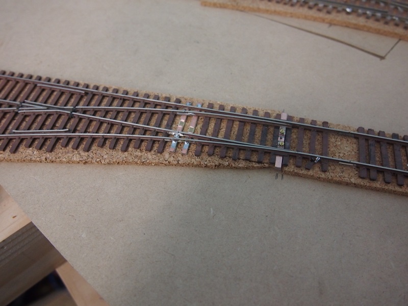
the tiebar mods can be seen - replacement using a PCB, that is drilled & tapped.
Once painted and ballasted, they are not that noticeable.
Ron
NCE DCC ; 00 scale UK outline.
NCE DCC ; 00 scale UK outline.

Posted

Full Member
Thanks for the photographs. This method did pass through my mind, but I didn't fancy drilling and tapping fiberglass composition board as it doesn't take to tapping threads that well. It's simpler to just remove the Shinohara tie bar and replace with a copper-clad tie and solder the ends to that directly rather than cutting the metal bar in 2 and screwing to copper-clad. Shinohara with their central rivet built-in some rotation movement at either end, it's actually a very clever design.
I think I know why your friend tried to keep as much of the original mounting as possible, Shinohara have a spring mechanism at either end that is supposed to lock the points in place. I don't need that as I'll be using a combination of Caboose Industries ground levers and Tortoises, so spring locking is superfluous. It looks like the blades have been moved closer to the stock rails as well. Has you friend switched the points and determined whether the curved rail flexes with a track gauge or micrometer? My distance is limited by the throw of the ground lever (which should conform to NMRA standards).
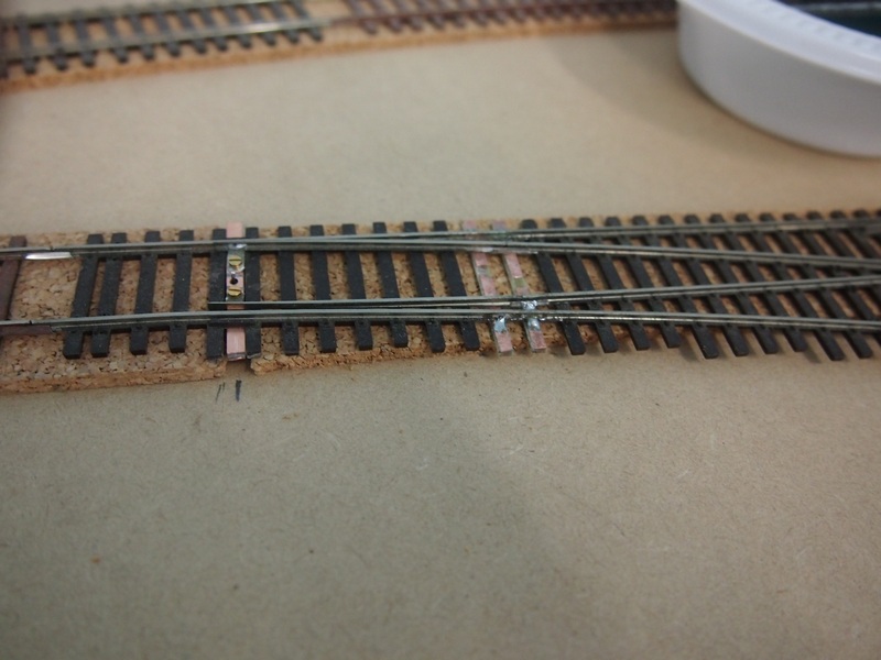
From the photos it looks like the Shinohara joiners are still being used but they now appear to be soldered to the copper-clad ties, which are not floating as they seem to be soldered to the stock rails as well. As supplied the joiners are soldered to the point blades and are a loose fit on the closure rails, so there must be a decent turnout motor driving the turnout as there is no rotation possible around the point blade head.
I noticed from the photo's that your friend seems to have kept the original shorty blades. One reason I lengthened the blades was to have less resistance on anchored blades with code 100 rail when switching the points, but I think I'll stick to flexible droppers and keep the joiners for locating purposes rather than anchoring everything in place. Two less copper-clad ties as well in a difficult area to solder (which would be avoided with longer point rails), plus too much stress on the copper and it will eventually delaminate from the glass-fiber core. If I was using code 70 I'd probably go for anchored ends as the rail is a lot more flexible than code 100, but I'd still use lengthened point rails (even longer than I'm using now), cutting down the closure rails to accommodate them.
One thing I've noticed with Shinohara rail - it drifts in the tie holders. It's a good idea to make those isolating gaps solid, either with CA and styrene shims or epoxy. I think your friend has done this (it's difficult to tell from the photos).
Couple of useful tips. Copper clad ties look a lot neater if the isolating cuts are made close to one of the rails rather than in the middle, and a graphite pencil stops solder from going where it shouldn't.
As usual in this hobby, there is always more than one way to do it.
Nigel
©Nigel C. Phillips
Posted
Site staff
Ron
NCE DCC ; 00 scale UK outline.
NCE DCC ; 00 scale UK outline.
Posted
Full Member
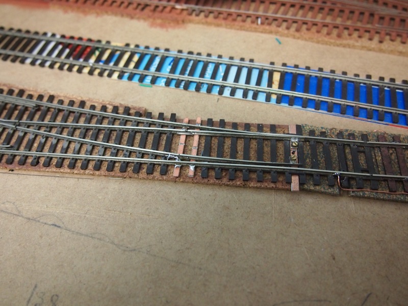
They didn't look like Shinohara fishplates (which have embossed bolt/nut heads). Are there bridges between the closure and point rails or is that still a loose fit connection? Difficult to see from the photos.
Shinohara springs are subtle - they are a piece of brass underneath the soldered rail connector that is compressed by the underside of the stock rail. However, I just checked some older code70s that I have (with the double connector between the point rails), they don't have them.
Nigel
©Nigel C. Phillips
1 guest and 0 members have just viewed this.