Scalescenes New Warehouse Kit
Posted
#223692
(In Topic #12204)

Full Member
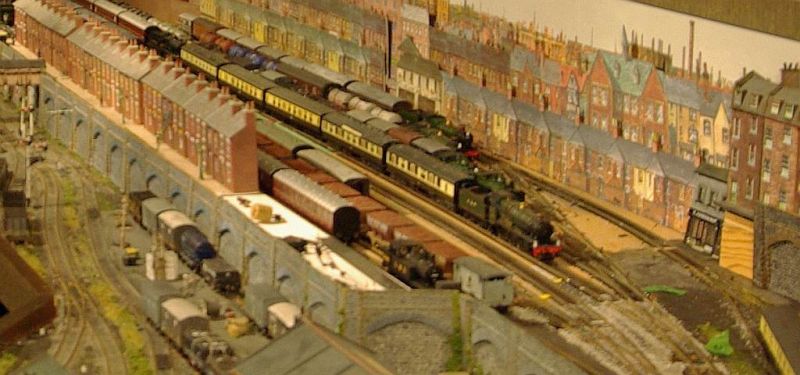
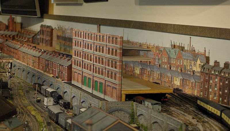
Modified to screen the storage yard at Granby
The fiddle yard is the first thing visitors see when they enter the Train Room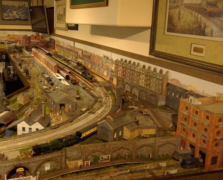
Within the room the storage yard is hidden by a long row of Metcalfe terraced houses with the exception of the space at the end
This desirable piece of real estate has been vacant and undeveloped for about eight years while I pondered on the best way of building something that would fill the space…..and stretch over some sort of bridge to shield the yard from the entrance to the room.
I started building the Scalescene Low Relief Warehouse kit before Christmas but made little progress. The problem being that one unit was too small and two units too big. Trying to build one unit and combine it symmetrically with two thirds of a unit was challenging. Fortunately my problem was solved when John Wiffen announced his new improved Warehouse kit.
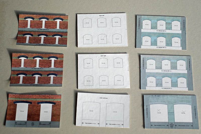
The new kit is typical Scalescenes relying on building up a series of sub assemblies of laminated card which are then strengthened further with vertical buttresses/columns and horizontal plinths and ledges. This kit can be extended vertically and/or horizontally with lots of options for added detail.
I thought I would just post a few photo showing how the build is progressing rather than a detailed how to do it but always happy to answer any questions
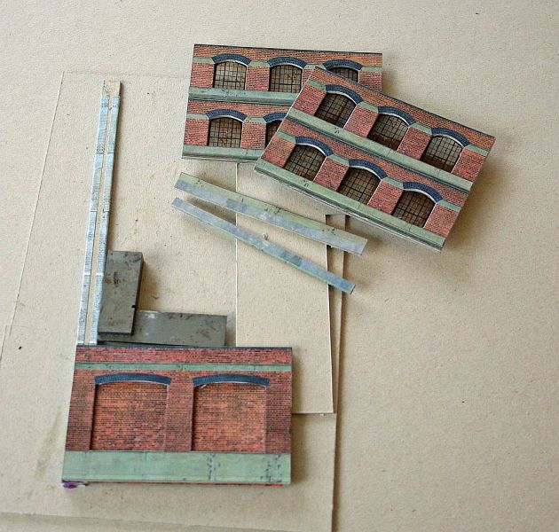
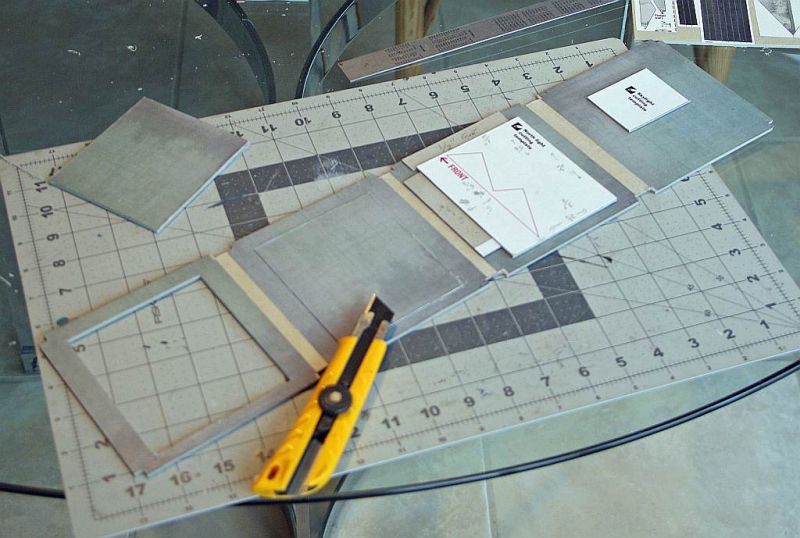
The three columns above will be combined to make one module.
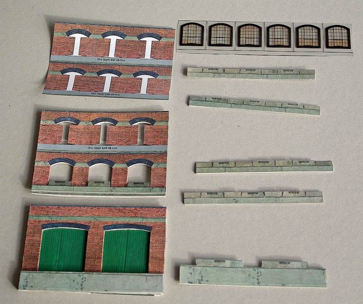
This shows windows plinths and window sills that need to be added
The window sill covering the full width are a big plus……..they were very fiddly on previous versions having to be applied individually.
The exposed arch cut lines look bad in these shots but its just the camera angle l

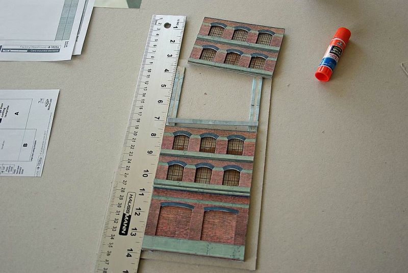
The default design has a base unit and one window unit. I want more height hence the second window unit
The base unit can be varied in a number of ways. Other options : full length arched doors,one over sized door or large windows
So now the components of each module have to be joined together plus a lot of cutting still to be done on the remaining two modules! I sure get through a lot of blades!.

Posted
Legacy Member
I admit to sharpening some blades for a while before throwing them away, get a bit more out of them that way.
Looking good so far John ,i will keep watching :thumbs.
reg
Posted
Full Member
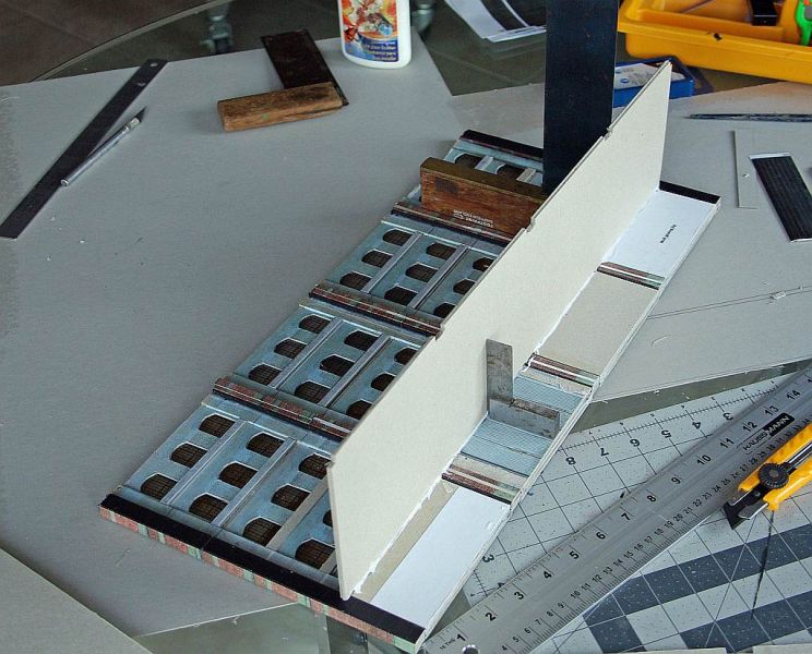
Each module contains 3 sub units.
A door unit, window unit and a second that I am adding
The base unit is glued to the interior buttresses as shown below
A ledge is glued to the top of the door unit followed by the first window unit
Setting three relatively small laminated units up like this sure exposes any cutting/glueing errors which I suspect know will haunt me later on :oops:
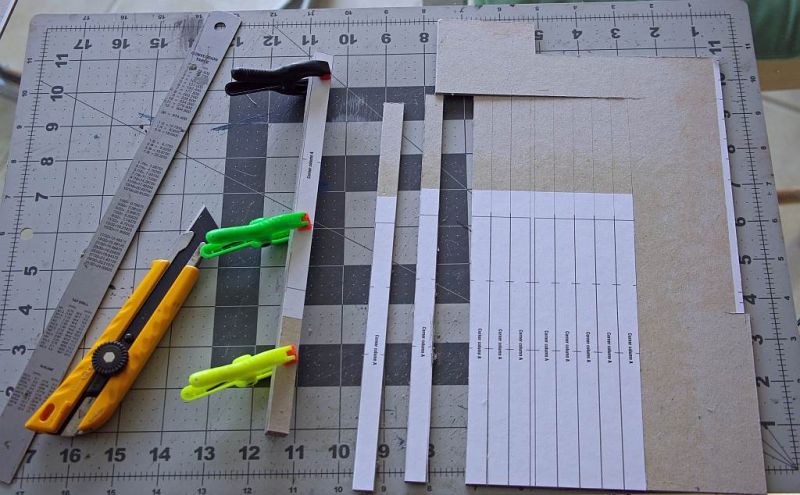
The modules are then glued to columns made of 5 sections of 2mm heavy card laminated together.
Here is my column factory
As you can see the column template only allows for the default door + window unit. Mine needed to be longer.
The instructions suggest constructing two separate columns……a regular length as per the template to which is added an extension …….joined together with a strengthening fillet in the centre. I decided to cut full length columns for greater strength and to try and ensure smooth surfaces on all four sides. I used the cutting marks on the template to measure out the extension.
Despite taking all manner of precautions I always have problems ensuring four totally smooth surfaces on these laminated columns. I am guaranteed two and I ensure the third by assembling and clamping an a flat surface…….and hoping I can conceal the inevitably uneven fourth :shock: There looks to be a particularly bad one below but its partly the camera….I hope
So having cut and laminated 5 columns the next job is to apply the cover layers

The final touch is to attach 1mm card wrapped in black paper to simulate a drain pipe.
Next step is line up a column and glue to a module.

Sadly the column is about 2mm short. It aligns perfectly with the default layout of Door + Window unit but does not align with the second window unit

The work around was to glue a second extension cover layer as shown below…….

I guess I am getting very old and placid…….there were hardly any choice words……just a painful reminder that when doing a new build its better to do one sub unit at a time rather than a mass build……..just one column would have revealed the problem!
John specifies 2mm approx for heavy card and 1mm approx.for medium card. I use mill board….. its cheaper and easier to cut than mat board (UK mounting board). Heavy Millboard is exactly 2mm but the medium is about 1.2 mm. Most times (and I have built lots of kits) its not an issue but in this instance I guess it was
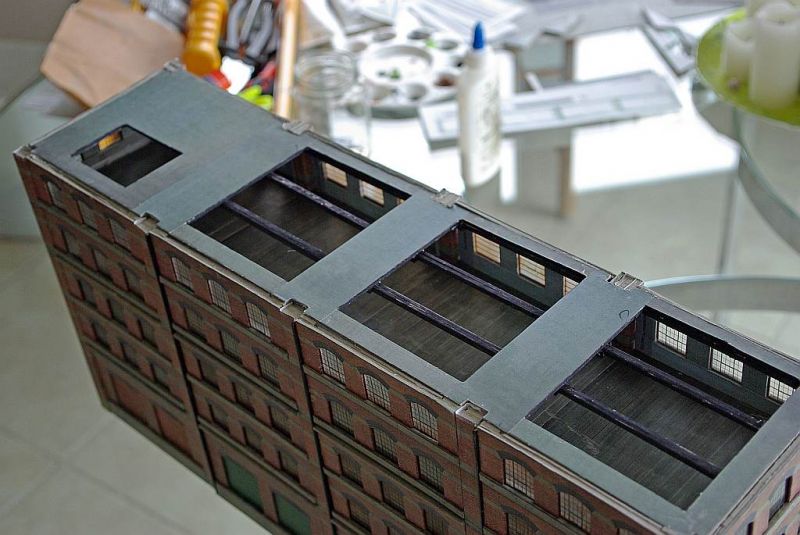
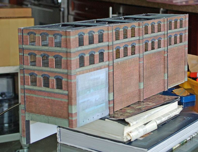
So finally here we have all 4 units butt jointed to the 5 columns.
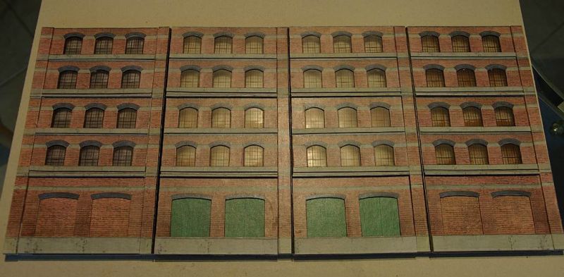
Floors and sides need to be added which hopefully will give it a lot more stability. Right now its quite flimsy….I had hope to photo it propped up in situ but didnt want to risk it
I am not a fan of butt joints…..laying a column over the modules as in the old warehouse kit creates far more stability and hides a load of errors.
In fairness the default unit consists of just 2 modules x 2 sub units………this is three times bigger 4 modules x 3 sub units……. I have perhaps been a bit ambitious……..time will tell!
Posted

Inactive Member
I have great confidence in you. :thumbs
Max
Port Elderley
Port Elderley
Posted
Legacy Member
Could be your printer was a tad out with that r/hand column that gave you a problem,
Looks OK now. I would be pleased with that if it was mine.
reg
Posted
Full Member
Thanks Max……You are always such a great morale booster!It certainly is an ambitious project, John.
I have great confidence in you. :thumbs

Cheers
John
Posted
Full Member
Hi RegI think you are doing very well John , its never as easy to do as it looks .
Could be your printer was a tad out with that r/hand column that gave you a problem,
Looks OK now. I would be pleased with that if it was mine.
Another great cheer leader :thumbs
All the pillars were out unfortunately even though I cut the extension pieces to John's templates.
My use of 1.2 mm card for the ledges will have accumulated up…….one minor error can quickly add up in a multiple build and I probably didnt not glue them in snug enough…….one lives and learns……..even at my age
Cheers
John
Posted

Full Member
I have seen comments from other people building the kit as standard having the same problem so you are not the only one with the problem.
Cheers
Andy
Andy
Posted

Full Member
A very clever method of hiding a yard within a "town scene".
Always an inspiration to watch developments on Granby - following it with interest. :cheers
'Petermac
Posted

Full Member
Ambition always brings challenges and so it follows that the challenge increases with one's greater ambition. Fortunately, your experience is more than capable in overcoming all slings and arrows and Granby continues onwards and upwards. Well done, it looks grand!
Bill
At 6'4'', Bill is a tall chap, then again, when horizontal he is rather long and people often used to trip over him! . . . and so a nickname was born :)
Posted

Full Member
Always try to look on the bright side of life!
Barney
Barney
Posted
Full Member
A lot of progress made this week
Hardly surprising considering the weather.
We went from this

To this overnight

and its still snowing
I have added flooring to the front section and it is now far more stable.
The instructions specify individual floor be cut for each module which are subsequently joined together with support tabs.
I thought it would be more stable if I cut the floors in continuous lengths for all four modules
This is the lower floor being fitted
I double laminated this floor and its glued lower than the plan because, as you will soon see, it will rest on a piece of 1/2" ply that hangs over some of the storage sidings

These are floorboard overlays being set up. I dont normally bother with interior detail but in this case there will be loads of skylights on the roof and windows all round …..so I will finish the top floor
Fortunately I measured the floors from the completed front section rather than the individual templates. You can see a 2mm gap above…..which would, of course, have accumulated with each module!!
The next shot is of the underside and the joist template

The joists are 2 x 2 mm card laminated together……4 joists per module 16 joists per floor.
4 floors……..64 joists 128 pieces of 2mm card……….the mind boggles. I compromised with just three floors ……..double laminated the base floor and only 8 joists on the centre floor.
Because of the length i inserted a couple of interior walls. Its now :thumbs solid as a rock and thats without sides or back
Here is the unit roughly in place on its base over the sidings

The next job is to produce 2 sides each of one module and a back of four modules. The unit can be seen from all four sides so all the modules will have to follow the same process as the front except they have to be 2 3/8" shorter
The top floor seems to be sagging but that should be corrected (I hope) when the sides are attached


I havent made up my mind about the space…..I may build a low relief pub and either put it there or shuffle the terraced house up and put the pub next to the shops.
There is a lot more to do before I worry about that! First job tomorrow is to run a few trains…….round and round to make absolutely certain my clearances are good…….the spaces between a couple of sidings are very narrow and I have a wafer thin support which seems ok …..but better safe than sorry
Best wishes from Vancouver
John
Posted

Site staff
Ed
(PS You've a wagon derailed at the back
 )
)
Posted
Legacy Member
reg
Posted

Full Member
Proper Preparation makes for Perfect Performance!!
http://yourmodelrailway.net/view_topic.php?id=13331&forum_id=21
http://yourmodelrailway.net/view_topic.php?id=13331&forum_id=21
Posted
Full Member
Thanks for the heads up Ed……I hadnt spotted that one :oops: Took me a while to sort how it happened there then I remembered that I lifted the loco off……..as part of my mega weathering project :roll:
Ron The clearances worked fine thankfully :thumbs……….I have a number of T shirts from failing to do elementary checks in the past :oops:
Cheers
John
Posted

Full Member
'Kev
Posted
Full Member
I have got rather behind with my updates……..the last couple of weeks has been what I call " in the trenches" mode. …….lots of cutting and pasting but not exactly newsworthy.
In fact I became too enthusiastic with the task….sitting too long doing repetitive cutting is not recommended for pensioners with back problems. Enforced bed rest delayed the project somewhat.
First job was to fit the sides. They are a single module wide but have to be reduced in height because the unit overhangs the storage yard. It a good illustration of the kits versatility. I used one full window unit (2 rows), cut a second unit down to one row and chopped 3/4" off a plain base unit. I made the construction simpler by eliminating the sub assemblies and mounted the cutting templates (carefully!) on to a single base card rather than joining 3 separate base cards as I did at the front.
 .
.Next step …..the roof. The instructions call for 4 separate roof units which are then butt joined together. I preferred to cut one unit measured to fit the entire length…..thus allowing for the dimensionall discrepancies created by me using mill board. It is also easier to fit and more robust
Here is the roof being cut out
The cut outs are for 3 North Lights and a Skylight. You can also see the notches cut out to accommodate the columns.
4mm Joists were added for the entire length making the sub assembly quite rigid
I dont think individual roof units would have worked at all well.
The shot above shows the back in place but in reality the back is closed in after the roof is fitted
As with the sides, each module is a single piece of base card sandwiched between columns. The viewer will see very little of the lower section because I am going to scratch build a boiler house on the module with the internal brick
Next job making the North Lights……heres the assembly line
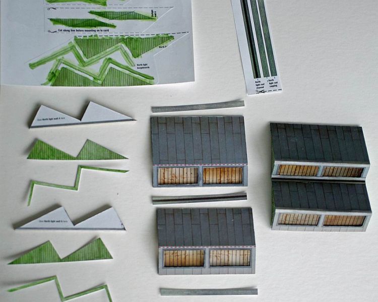
I made a lot of these for the Engine Shed and this is definitely an improved design. Its still very fiddly, as you can see! A good tip is to bend the roof unit into shape immediately after scoring the ben line and before cutting out the window apertures.
The woodwork prints out as pale silvery grey. I wanted it to have some relationship with the green doors at ground level so I washed with diluted green rather than proper painting because I wanted to keep the printed detail. Its a bit crude right now but weathering should improve the look.

I am going to add a plant room/lift house behind the skylight.
A Hipped skylight assembly is a third roof window option. It is a very flexible kit …..all sorts of choices. You could just leave the roof plain if you wish.
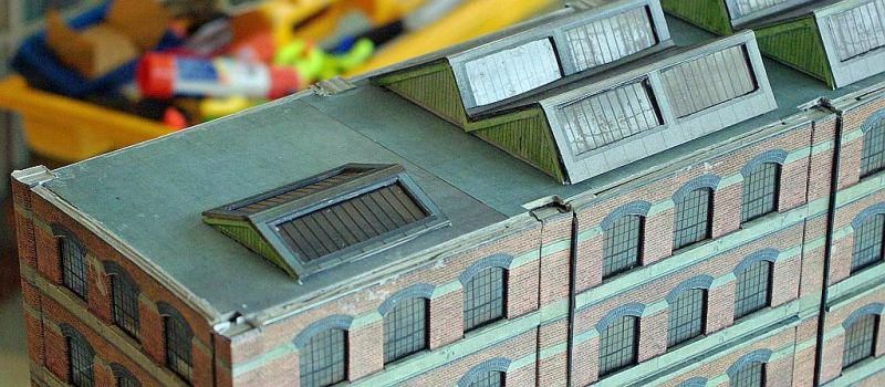
Cruel closeup but a reminder of the problem I have with the front columns being 2mm too short……….fortunately I have devised a cunning plan which will level everything before I start installing the parapets later today
Posted
Inactive Member
I love "cunning plans."
Max
Port Elderley
Port Elderley
Posted

Full Member
1 guest and 0 members have just viewed this.