Members Workbench
Posted
#218707
(In Topic #11919)

Full Member
Wire in the Tube Point Control
Hi All I am building a Second Puzzle Layout, why? I don't know really, but that's it. A bit more to it than the first one.I had asked Ron (g0ibi) if I could use his idea? and he was okay with it. Ron didn't use WIT point control, but, to an ordinary blokelike me it seemed a good idea. The first WIT points worked without problems, and I am using the same method this time, a DPDTslide switch set at a distance, with a large radius bend in the wire(no sharp corners). When the point is set normal or reverse,dependent on being a R/H or L/H point, the switch pulls the blades towards, but it dose not push the blades away, but,here's the thing, once the blades have been set, ""Towards" unless the switch is pushed, the blades are under tension and cannotbe pushed by "by the finger from the sky technique", so that means that it should work, but, why? does it not work??Please any sensible easy to follow solutions would be appreciated. all the best Kevin
Staying on the thread Kevin.

Posted

Site staff
I have used WIT and still do.
http://yourmodelrailway.net/view_topic.php?id=1733&forum_id=6
http://yourmodelrailway.net/view_topic.php?id=14259&forum_id=6
Ron
NCE DCC ; 00 scale UK outline.
NCE DCC ; 00 scale UK outline.
Posted

Site staff
I can only guess that the wire is flexing and not held rigid enough when you push the switch back.
Can you move the switch so that there is less of a bend in the WIT.
Straighter the better, is the way I always approach these.
Ed
Posted
Full Member
Staying on the thread Kevin.
Posted
Full Member
all the best. Kevin
Staying on the thread Kevin.
Posted
Site staff
If you measure (as far as is possible) the distance the slide on the switch moves and the distance the switch blades on the points move, you'll probably find they're almost the same.
So where as you might get away with some flexing in the WIT with a lever, you may not with a DPDT slide switch.
Ed
Posted
Full Member
Staying on the thread Kevin.
Posted
Full Member
Staying on the thread Kevin.
Posted
Site staff
I have on a couple used the other side of the switch to power the appropriate deliberately isolated rail, on each of the approach roads to the heel of the point.
This stops me running a train into the point when it's set against it, preventing derailments and short circuits.
Only works where you have reasonable lengths of track running into the heel of the point though, not much use in yard areas where there may be a number of points close together.
Ed
Posted

Full Member
Did you put omega loops in?
Nigel
©Nigel C. Phillips
Posted
Full Member
But, this time around "No", maybe I should have, my original wire for the
WIT and the brass tube were heavy duty, and it would have been necessary to use Omega Loops or Hoops? to connect to the tiny hole in the throw bar. As it is the wire that I am using is both fine and springy,(the packet comes with a health warning, to wear Eye Protection), if it was soft it couldn't cope with pushing the throw bar.
If you think that would solve the issues I have had. Incidentally. at various times I have had all four points working, and then I noticed that one of the points towards the centre of the group was "Severely" out of line. After lifting most of the track, I had to start again, good fun this.
Please advise, all the best. Kevin
 Last edit: by Passed Driver
Staying on the thread Kevin.
Posted
Full Member
Is the DPDT switch throw (distance) the same as the switch blade throw (one side to the other)? If the DPDT movement is greater than the switch blade movement you could be binding the wire in the tube. Which is where an Omega loop would help by acting as a spring. You use Peco turnouts, so as soon as they cross the middle they will snap in place. If the switch rail blade is not touching the running rail the cable is too short and under tension. Which could also lead to poor running through the points.
Nigel
©Nigel C. Phillips
Posted
Full Member
Staying on the thread Kevin.
Posted
Site staff
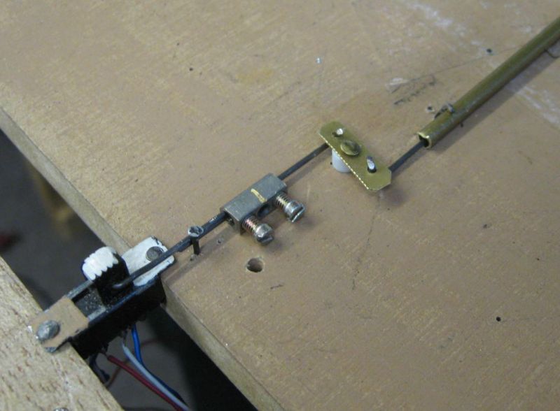
The brass bar changes direction and the two screw block ( removed from plastic terminal strips) allows adjustment - the slide switches are just perfect for Peco Code 75 turnouts.
Ron
NCE DCC ; 00 scale UK outline.
NCE DCC ; 00 scale UK outline.
Posted
Full Member
Then when I purchased the thinner wire, mostly it worked, I realised it's potential, Now I have two shunting puzzles, the first with two sets of points working as they should, but the the second puzzle, I (sought permission ) copied from another Ron, and that has four sets of points, all these points had been working well, until that is, I drilled the holes too close to one particular point, and shifted it( now it is proving a bit of a devil) causing a failure, but I have to be careful so I don't disturb the other points, it might have been better if I had ballasted the track first then that way the track would have been stable. If I ever figure it out ( taking photos or video for adding to my thread ) I will be able to show you how I got the points to work. I chose to use similar slide switches for my points for convenience as both of my puzzle layouts are made to fit into a "toolbox" to make them portable, and the lid/s would not close with the taller levers(designed especially for mode railways) as recommended to me on YMRC. all the best. Kevin
Staying on the thread Kevin.
1 guest and 0 members have just viewed this.