Great Northern EMD SD-7 HO scale
Posted
#225715
(In Topic #12310)

Full Member
An unexpected repair!
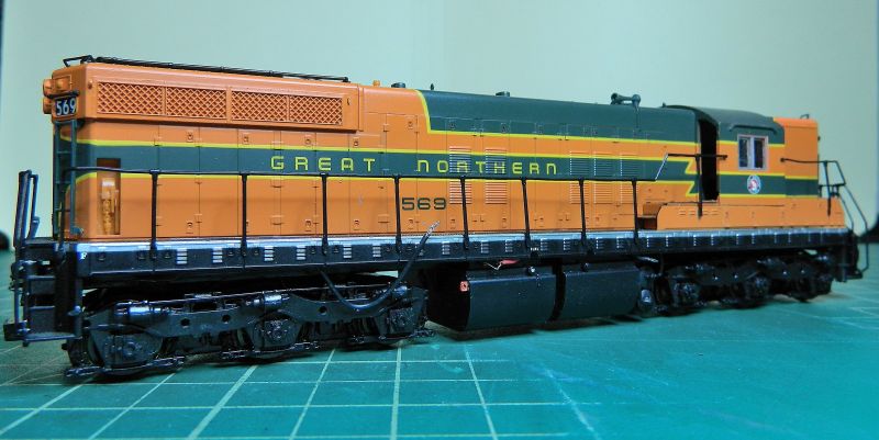
Hi All,The latest addition to the Great Northern roster is a Great Northern EMD SD-7 diesel electric (Co-Co trucks/bogies, Special Duty road switcher, 1500 HP). This is a DCC ready Life-Like Proto 2000 HO model that I picked-up cheap ($25) because of some deep gouges on the body work (cab roof and short hood, minor scuffs was the description. Ho Ho.). First photo shows the beastie, that loose pick-up wire should be inside the shell.
I repaired and repainted the gouges, and I was starting on replacing the DCC ready light-board with a wired DCC 8-pin socket in preparation for converting to DCC, when twitch went the shoulder, and the chassis hit the floor short hood first from 4 feet up. Truly one of those "well I never, would you believe it" moments. My wife says that lost a lot of meaning in the translation, and it was a good job the grandchildren weren't around.
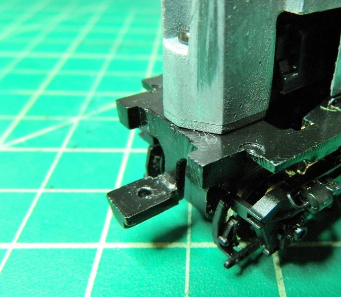
So, what was the damage? One mounting for the coupler snapped off, plus one bogie/truck in bits and pieces. The bogie/truck went back together fine, no damage, but that mounting is toast. Next photo shows what the coupler mount on the long hood end looks like.
And the next photo shows what the short hood end coupler mount now looks like.
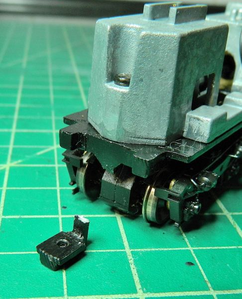
This is a MAZAC/ZAMAC chassis, one of the few things I won't attempt to solder. So I'm looking at the broken coupler mounting, and thinking "this is not good". Unlike many railroads, the GN ran their hood diesels long hood first (more protection for the crew in case of a collision), which means I need that coupler functional to pull the freight cars. CA is definitely out as is epoxy. The bracket is actually bent, and this alloy doesn't take kindly to bending. Flipping the body shell/chassis end-to-end is is probably out as the fuel tank/air reservoirs are handed.
So it looks like I'll be filing flat what remains of the coupler mount, drilling and tapping into the chassis base plate, and attaching a piece of right angle brass bar for the coupler to mount on. Which means disassembling the chassis plate from the chassis, removing the trucks, removing the motor… you get the general idea. I'll take the opportunity while I'm doing this to remove some metal from the top of the chassis to accommodate the DCC speaker which will go under the fans. And as I'm disassembling it a good lube of the bogies/trucks (Labelle 106 plastic compatible grease with PTFE) and a general service. And I've ordered one of those HD foam anti-fatigue mats to work on.
Any ideas/suggestions other than filing, drilling and tapping much appreciated. I'll post on the progress.
Nigel
SaveSaveSave
©Nigel C. Phillips

Posted

Inactive Member
I have a friend who dropped a Walthers loco and broke the chassis. I was able to source a replacement from Walthers. It was a bit of email faffing, but I got it eventually - together with some other bits and pieces that they threw in to clear the SKU.
It was only the cost of the emails and time to source it - plus a minimal cost for the part.
Max
Port Elderley
Port Elderley
Posted
Full Member
I checked with Walthers, who took over the P2K range a few years ago. No luck. Nothing on ebuygum either. This is one of my dontspendalottadough projects, so it's going down whatever is in the spares boxes pathway. If I can straighten the post I might have a go at drilling and tapping that, but I recon 5 minutes with the big file is probably the way to go, followed by some brass bar bent to shape and screwed into the chassis (or even a piece of brass square section).
Nigel
©Nigel C. Phillips
Posted
Inactive Member

I was wondering . . . could you fabricate a new bracket and fix it to the flat end of the chassis?
Max
Port Elderley
Port Elderley
Posted
Full Member
That's the plan - brass bar should do it. Attaching it is where the drill and tap comes in.There is enough meat in the chassis base for this, and I could as an alternative drill into the bottom of the chassis either side of the fixing screw. I'm dismantling the beast this morning, so I'll probably make it up as I go along.
Nigel
©Nigel C. Phillips
Posted
Full Member
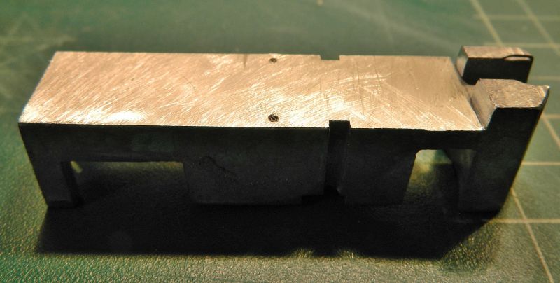
Some butchery with the big file this morning. I now have a flat surface on which to attach a brass coupler mount. I also took the opportunity to remove some alloy from the top of one of the castings to allow a decent sized loudspeaker baffle. Couple of pictures so you get an idea what's happening:
Dismantled chassis. Trucks are kept well away from the metal removal.

Broken coupler mounting filed flush with the frame plate.

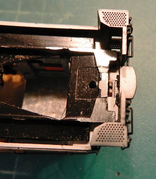
Test fit of the body shell to see how much room is available for a piece of brass to be attached to the frame plate. Plenty. It can run across the frame plate, attachment with some 2/56 bolts at the ends where there is plenty of meat. I'm thinking 20 or perhaps 40 thou' brass with some fillets of hard solder to reinforce the bends.The real thing had what looked a Roman ram under the coupler, that could get interesting. Block of styrene filed to shape would be the easiest way. More research. I got a few detail parts for the coupler beam on Saturday as well.
Alloy removal from the chassis where the old circuit board and support posts sat. I removed about 1mm, not much, but past experience with these models has shown that's enough to ensure the speaker baffle sits nicely under the fans without the speaker membrane fouling the roof. I also lengthened the well by about 1mm on the right. Again, this makes sure the speaker is in the middle of the grilles.
Nigel
Save
©Nigel C. Phillips
Posted
Full Member
I ended up fettling a brass coupler mount using a CAD template (cardboard-aided design*) and 20 thou' brass laminated (3 layers overlapping) with 243° high temp solder (the hard stuff) using the big 60W iron and a chisel blade. Probably more akin to brazing than soldering.The brass turned red, I had to resort to a dip in water to keep everything hard. I then drilled and tapped two 2-56 holes for a couple of brass machine screws through the coupler mount and the chassis, as well as one through the mount for a Kadee coupler box. I currently have a 2-56 nylon screw holding the box in place. Pretty? No. Can I see it with the body shell on? No. Functional? Yes. Job done!
Nigel
Drilled, tapped and filed smooth 2-56 brass machine screws

Underside. Said it wasn't pretty.

*Cardboard Aided Design? See "Project Binkey on You Tube.
SaveSave
©Nigel C. Phillips
Posted
Inactive Member
Max
Port Elderley
Port Elderley
Posted
Full Member
Does the job. With a $25 locomotive that's about as much investment as it will get. Manchester screwdriver precision at it's best. Now to tidy up the body shell. Much abused but just about salvageable.Normally held on by plastic clips, all gone of course. I have a plan to fix that though (cheap and functional). It'll look OK from 3 feet.Tested the motor and transmission today after a clean and lube. Butter smooth and nary a wayward noise in DC, and for a change no split axles. It came with a Digitrax DH165Lo decoder (wrong decoder for a PK2000 SD-7, meant for a GP-7, MRP around $27), but It'll work with an adapter plug that's going spare.
Nigel
©Nigel C. Phillips
1 guest and 0 members have just viewed this.