Crossover from 2 turnouts
Posted
#220624
(In Topic #12018)

Full Member
Code 100 crossover using 2 left hand turnouts
Hi All,Photo posting back to normal (thanks, Martin), so onto this week's little project. I need a single left hand crossover in the HO module track plan, and was shocked/horrified/gobsmacked at the price of a new one. My previous conversions of DCC "decidedly unfriendly" turnouts into DCC compliant ones left me with 2 spare #6 LH ones (one not yet wired underneath and waiting for the tie bar), I read somewhere how this could be done using regular turnouts, cutting one exit rail out from each turnout, removing the ties from one of them, and sliding the naked rail of one turnout back onto the ties of the other turnout That's OK if the original size/length is unchanged, once it's changed it gets fiddly (especially around the frog) with 3 small ties making up each long one. All those butt-joints? Didn't think so. Copper-clad? Game on!
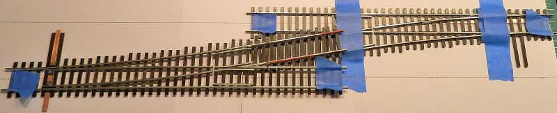
First photo shows the 2 turnouts one laid on the other at 2" track centers. The rails in red are the sections that need to be removed. Opposite sides for the lower turnout. All the ties for the crossover section were removed. I also removed the inner frog stock rails along with the ties and put them to one side. I didn't fancy cutting all those ties to match - and copper-clad ones going all the way across as in the prototypes would give better stability.
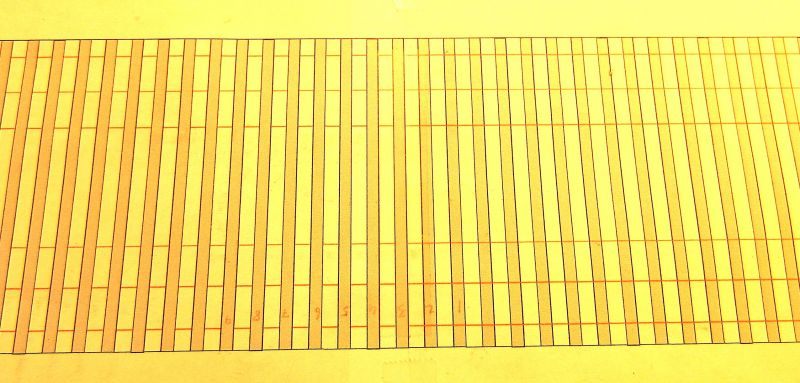
Second photo shows the template I used to position the 2 turnouts. No need for Templot here, 5 minutes with CorelDraw is all that is needed. Key points are the 2" centers, rail positions and the tie placements.
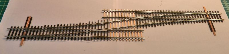
Last photo shows the final result after soldering up. I used HO scale sized copper-clad strip that is an almost dead match for the plastic ties width-wise, and more importantly height wise. The ties were cut to length, and fixed in place on the template with low-tack double sided "scrap-book" tape. The solder was Carr's 145°, and I used Kester organic flux. Two "Isle-O-Man track gauges were used to keep the rails still when I was soldering. Two ties on each end of the new work are plastic juxtaposed to copper-clad. These run under the frog, and I left well alone. A lot less insulating gaps as well. I finished off the wiring and tie bar on the uncompleted turnout (the one on the right). Afterwards I realized the tie bar ties and tie bars need to be moved to the the other side. A "well I never" moment ensued. That's a small "cut and shut" job for the ground lever ties as the copper-clad is plenty long enough on the other side.
That's it. Couple of hours work, $15 for the turnouts, around $1.50 worth of copper-clad and solder. List price for a code 100 left hand crossover is $41.99. Stock in length from a scale 40-80 feet moves through the crossover with nary a bump. If I can find a couple of right hand turnouts for the same money I'll do another one at the other end of the modules. That way I get a double crossover without the DCC wiring complications. Have to think about whether to motorize the 2 sets of points (stall motors) and have them interlocked so that the road is always set correctly.
Nigel
Save
©Nigel C. Phillips

Posted

Full Member
I cheat and use Peco points in that configuration and always wire my 2 point motors to 1 switch thus ensuring the correct road is always set and that the points change together.
I've had no power problems with either stall motors (Tortoise via a Lenz LS120 accessory decoder) or SEEP's (via a CDU). I certainly wouldn't advise switching them separately !! :roll: :roll: :roll:
'Petermac
Posted

Inactive Member
Max
Port Elderley
Port Elderley
Posted
Full Member
I would have simply connected 2 turnouts together except for the 2" centering. Peco turnouts are considerably shorter than the Shinohara ones, so I could probably have used them as is with 2' centering, but I really don't like those sleepers and point rails and it means shimming the Micro Engineering track, which means slopes entering and leaving the cross-over, then forget about fine-scale couplers…
Life would be a lot easier track-wise in Code 83 or even better Code 70. I'll get all this done and then bang, a new set of NMRA standards for modules will surface which specifies that new-fangled code 83…
Nigel
©Nigel C. Phillips
Posted
Full Member
Angus from Waverley Cross.
Posted
Full Member
Thanks. I think having an almost continuous stretch of track between the 2 frogs (insulation gaps excepted) rather than rail joiners half way along makes a big visual difference. Really down to the gang from Bodgit, Fudgit & Solderit.*
Nigel
*Whose motto is "Close enough, lad, when I nods my 'ed 'it it."
©Nigel C. Phillips
1 guest and 0 members have just viewed this.