Copper-clad sleepers/ties for hand-laid track
Posted
#222116
(In Topic #12113)

Full Member
Making the insulating gap
Once in a while a while we all get a light bulb idea. For many years now I've always cut a shallow groove in copper-clad sleepers/ties when building track, turnouts, etc, in order to isolate one rail from the other, placing it as close to one rail as practically possible. And always at 90° because that's how it's done matey (and we are creatures of habit when it comes down to it). We've had a bit of an going discussion on the site about whether a cut with a file introduces more weakness when compared with using a grinding wheel in a Dremel (or similar) to remove the copper layer. Personally I've found that both weaken the copper-clad, so it's one of those "yer pays yer money and makes yer choice" scenarios where everybody is right (or wrong, depending on which side of the fence you are).Earlier today I was cutting some pieces of styrene strips at 90° and 45° to make some cosmetic sleepers/ties, and was simply scoring the surface with the cutter blade and snapping between my pinkies as I couldn't find the NWSL Chopper. "Old on, sez moi", when said pinkies started to protest, it's a darn sight harder to snap at 45° than at 90° (quite a lot, try it and see). And even more so at 30° (next to impossible, the styrene just twisted). Which when you think about it makes sense.
Then the bulb went on - why am I not doing this with copper-clad ties. So I did a quick (empirical) test. It's relatively easy to snap copper-clad after a light insulating cut at 90° made with the edge of a triangular file, it was next to impossible with a 45° cut and impossible with a 30° cut. Bingo. :thumbs :thumbs :thumbs (Hold on, I've only got 2 of these).
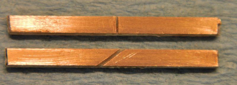
Unfortunately it means I'm scrapping the double crossover I'm building which has 90° isolating cuts, and starting with fresh copper-clad with angled cuts. Picture shows what it looks like. Same depth on both, as I built a jig to make sure.
Nigel
Save
©Nigel C. Phillips

Posted

Full Member
John
John
Posted

Site staff
Ron
NCE DCC ; 00 scale UK outline.
NCE DCC ; 00 scale UK outline.
Posted
Full Member
It's the tie bars I had in mind, most of the sleepers/ties in a turnout get very little stress, and in straight track zilch. The problem with the double crossover is that it's one big set of frogs held together with long bits of copper-clad. No tie bars, but I've a few RH turnouts to build. The stress areas there are the tie bars and the junction twixt the blades and the closure rails. Unless there is an inordinate amount of slop there will be tension at both ends. If the tie bar is tight the closure junction needs to be loose. Vice versa.
Hi Ron,
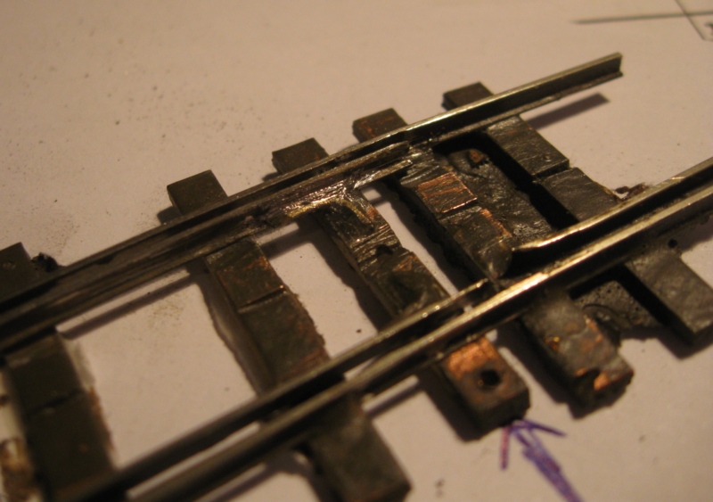
What side are you soldering the angle to - the inside? As I mentioned, the issue with the tie bar is that it does not move in a straight line because the rails are following arcs - 2 separate and distinct ones, so the rails are alternately being stressed on different sides, and the side where the blades meet the stock rails needs to be tight.. John is using a pivot (the brass pin) through the tie bar to allow the blade to turn independently, which will I think need a bit of slop to accommodate the fact that the ends of the blades are not moving parallel to the tie bar (which will be restrained by the motor wire). I've yet to have a tie bar fail, but I have read that it can happen. Probably because of lack of attention to the geometry rather than intrinsically bad soldering or a weak solder junction. I'm starting over because a 30° cut is a lot less noticeable than a 90° cut. I played around with scale diagrams just to make sure.
Nigel
©Nigel C. Phillips
Posted
Site staff
the blades are not hinged but flex for 4"/100mm without problems. On my 3 ways units, flexing is down to 3"/ 75mm
and yes, I have never filled in the gaps, let paint and ballast dust do it !
Ron
NCE DCC ; 00 scale UK outline.
NCE DCC ; 00 scale UK outline.
Posted
Full Member
Peco code 75 small OO turnout: 2.5mm
Peco code 124 O turnout: 3mm
My turnout: 2mm (I used my flangeway gauge) and it remains to be seen whether wheels will have problems. My limited testing seems to indicate that they're good.
Point is that the stress on the hinge isn't large whatever you do. However, a solid solder joint between rail and tiebar will see greater stress than a hinged one.
Empiricism rules.
John
John
Posted
Full Member
Yes, it's a small distance. However, if you want another giggle, solder up the connection between the closure rails and the blades, and solder the points to the tie rod. Then see how much resistance you have when you move the blades across. Especially with code 124 rail. Having that pivot is going to make a world of difference, and I'm definitely going to give it a try with the turnouts.
Hi Ron, Thanks for the confirmation. As I said, rigid at one end means slop at the other.
Nigel
©Nigel C. Phillips
Posted

Inactive Member
I have 12" long point rails in Code 143 which are 10" from the last attachment; with no hinges.
At rest (disconnected from the motor), they sit midway and deflect 1/16" each way when thrown.
They are soldered to the throw bar, right across underneath the rail foot but now I'm leaving hatches in the infill so I can do the thing with the rod, later on, if required.
So far, so good.
Max
Port Elderley
Port Elderley
Posted
Full Member
Nigel, I think that intuitively, the brass pin hinge is better although it takes a bit more work to set up.
John
John
Posted
Inactive Member
I'm mainly concerned about the connection to the throw bar, but I can always go back and beef up the joint if necessary.
I'll leave it for now, but keep a close eye on it. :shock:
Max
Port Elderley
Port Elderley
Posted
Full Member
John
John
Posted
Full Member
When I rebuilt the Shinohara turnouts (code 100) I used a semi-floating heel, with the rail joiner soldered to the blades but not the closure rails (as original). Shinohara opened the ends of the joiners up a bit to allow the blades to move laterally. Just soldering a connecting wire from the bottom of the joiner to the closure rail stiffened things up dramatically. I stuck with the blade-stock rail gap throw that Shinohara had used, 2.8mm (around 1/8"). Same distance on my Peco Code 83 turnouts. Which is way too generous for modern stock. NMRA site is down at the moment, so I can't check there. Real life was 5", which in 1:87 is 1.46mm (1/16"). The templates I normally use from Fast Tracks have a throw of 2.25mm and are supposed to be NMRA compliant. Some adjustment is probably called for, the less throw on the point blade the less resistance.
Nigel
©Nigel C. Phillips
Posted
Full Member
Even 2.25mm seems large (given that Peco code 75 is 2.5mm). Finescale track has 1mm flangeway so the answer probably lies somewhere in between. If you've controlled your wheels standard you can probably build tighter, but if you have to play with others, you might need to stick to NMRA.
(Aside: I read that Peco are mulling a new range of track and turnouts with code 75 BH rail. Track is supposed to be first and, subject to decent sales, Peco will release turnouts. It's a chicken and egg thing I think because those people who care about such things won't want to mix BH track and FB turnouts.)
There is less excuse for O gauge I think because wheels tend to be more of a constant standard.
John
 Last edit: by Brossard
John
Posted
Full Member
Correction, the 5" I quoted is I believe the NMRA standard (to allow for over-scale wheel flanges), real life is often nearer 3.5", which comes down to a minimum of 1mm in HO, 1.12mm in OO, and 2mm in UK O scale. I just checked the flanges on some old HO diesels from the 1970's and 1980's, maximum I came up with was 0.95mm on an Atlas/Kato RS-1 diesel. Freight cars and passengers cars were between 0.8mm and 0.9mm (and some of the old ones waiting new wheels had pizza cutters).
The Shinohara turnouts I used have excessively wide throws to allow for polarity changes (both point blades are connected, power routing approach), something I should have checked. I suspect this is a legacy with the Peco turnouts. So now I have an excuse to go back and refit with angled isolation cut tie-bars and a throw of 1.46mm as the polarity now follows that of the stock rails.
It might also be worthwhile replacing the currently separate closure rails and point rails with one piece and getting rid of the rail joiner or using a brass-strip hinge in the web. I'm not sure how a throw of 1.46mm will work with those Caboose Industries ground throws, which have a throw of 0.165" (4.2mm). Which begs the question, would they have worked properly with a throw of 2.8mm? I may have to go to manual throws underneath from Fast Tracks (which I want to try anyway).
If the turnout is properly wired for DCC (and DC) short circuits should not be an issue, which of course they are with the original power routing.
I can control my wheel standards, this exercise is for the modular club track, where there are some old clunkers that come out every now and again with their wagon wheel treads and flanges. Mind you, if I stick to NMRA standards and the club specifications follow NMRA standards…
Nigel
©Nigel C. Phillips
Posted
Full Member
Of course flanges are probably wider than the real thing. In OO/4mm flanges are typically up to 0.8mm thick, whereas finescale is 0.5mm, that makes quite a difference in acceptable flangeway. Tyres on the real thing are about 6", so 2mm in 4mm scale - this agrees with P4 (EM is 2.2mm).
I was thinking of your having to cater to your colleagues with their ancient stock. Wicked of me to tempt you to deviate from the good book.
Probably you can get away without a loose heel, although I guess it doesn't hurt. Rail is pretty flexible.
It's all good fun though.
John
John
Posted
Inactive Member
I have a further complication - particularly on the turnout nearest the gauntlet. To negotiate the slipway cut out, the curve facing the heel end of number 1 turnout is a very tight radius. I haven't measured it, but it's very tight.
The others aren't much better, as I wanted to fit all six on to the centre module.
The wheelbase of my loco is 10 1/2" so I need the full 1/8" clear space on the inside point - otherwise, the loco climbs on to the point rail.
It's not very pretty, but once the infill goes in, it's not so noticeable.
Max
Port Elderley
Port Elderley
Posted
Full Member
John
John
Posted
Inactive Member

Stand by . . .
Max
Port Elderley
Port Elderley
Posted
Inactive Member
You can see the tight curve leading into the gauntlet on the left.
Allowance for the foot of the far point rail has caused the large gap on the infill. Once the outer filler pieces are installed, it shouldn't look too bad.
I just re-noticed the crappy soldering. I must fix that. :oops:
Max
Port Elderley
Port Elderley
Posted
Full Member
It's a short transition from the curve to the switch blade, that could be problematic.
Amazing what photos show up.
John
Just a thought, the switch blades look a bit thick, is the gauge OK at that point? Should be 29mm IIRC for F7.
Last edit: by Brossard
John
1 guest and 0 members have just viewed this.