Battery power, radio control, dead rails
Posted
#216891
(In Topic #11842)

Full Member
Testing, testing
After a fair amount of armchair research I decided to give the Stanton system a try (S-cab.com). The box of bits arrived earlier this week, 2 BPS units (battery power supply, one long, one short) that control the battery input/output as well as charging the battery, 2 Li-Po 500 mA batteries, one radio transmitter, and a DC-DCC radio receiver that drives a regular DCC decoder. All this will interface with my current NCE Powercab system. First 3 locomotives for the UK stock evaluation will be a Lima GWR diesel rail car (long BPS), a Bachmann Collett Goods DCC ready (so the box says, we'll see how good that claim is) with the large tender (short BPS) and a Hornby 14xx with a push-pull autotrailer into which the electronic parts and battery will have to go, not a snowballs chance in the engine. I may have to remove some seats from the trailer but I'm thinking the roof space may be a possibility.What comes first depends on what comes first out of the storage box. Naming of parts in the next post.
Nigel
©Nigel C. Phillips

Posted
Full Member
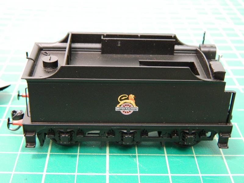
First test locomotive for the BR/WR plank is a Bachmann Collett Goods, early BR black, with the tall tender. Some cosmetic valve rods in red would help matters visually (can I get them to go up and down though?). It's currently in OO gauge, it will be eventually converted to EM gauge. Small can type motor in the boiler mounted vertically driving the rear wheels, there is space forward for a small decoder if desired (with some metal removal from the boiler weight).
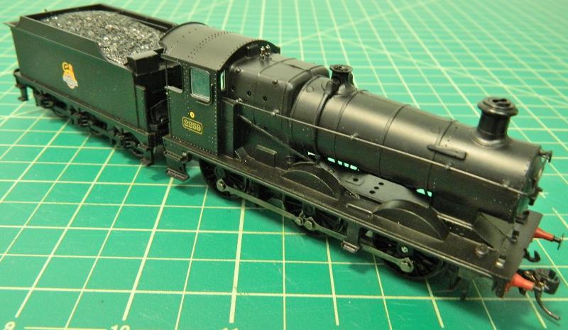
The tender is the intended place for the electronics needed for radio control, more space is needed with the system I'm using compared to the DelTang one as it will drive a DCC decoder. I also want battery charging from the track, either on the move or at a track charging station. Again more space for the electronic unit required for this.
The tender top is secured to the chassis with 5 screws, one at each corner and one underneath the NEM coupler pocket, which requires that the coupler be pried out with a small screwdriver to expose the screw. The bottom then pulls off vertically.
First shot shows the coupler bar for the engine end and 2 of the screws. Holes already in place for a (small) speaker. The wheels and axles are definitely a throw-back to OO gauge tolerances (anything between 12.5 and 14.5mm) and overly large frog gaps.

Second shot shows the other end with that hidden screw going through the NEM coupler pocket slot and into a post on the tender shell. The ends vertically as the holes locate on the screw pegs.
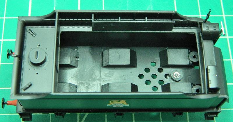
Next 2 shots show the tender chassis with the weight nicely placed over the speaker holes (go figure that one!). This definitely is one of Bachmann's "DCC Unfriendly" models.

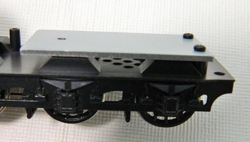
Off with the weight to see what we have underneath. Couple of plastic posts at the engine end that serve no purpose. They will have to go, as will the weight. Plus those weight support rings serve no purpose either and take up space. The wheel wells are unnecessarily oversized as well (as a result of that sliding bearing tube). Narrowing them will give almost another 4 mm of width.
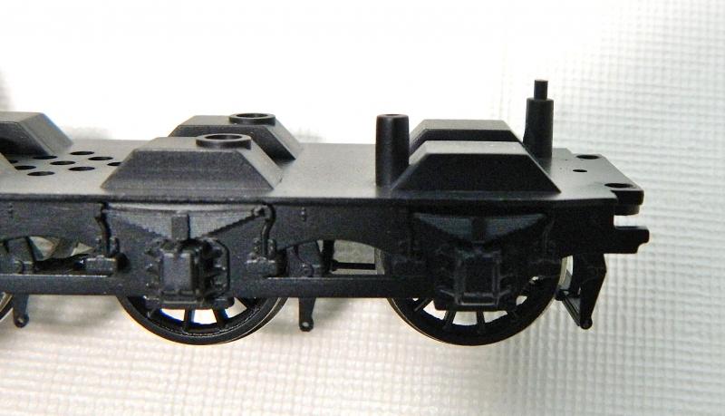
The tender has a metal lump on top to represent coal, underneath there is a well for the coal if an almost empty load is modeled. That will go, as will most of the rest of the "floor". A new coal load will be made-up from styrene and real coal with holes to let the sound out (my preferred method). Having a "heaped load" of coal will give me another centimeter of height for the decoder and speaker (and was quite prototypical if the engine was out for the day on a branch line without coaling facilities).
Top view.
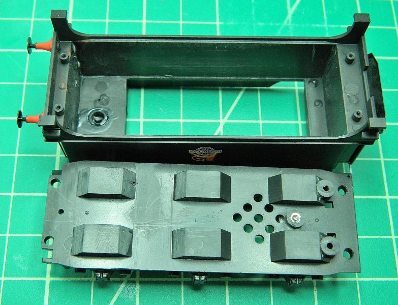
Bottom view.
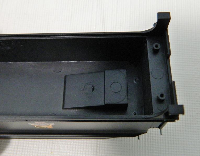
That should give me enough room for the electronics.
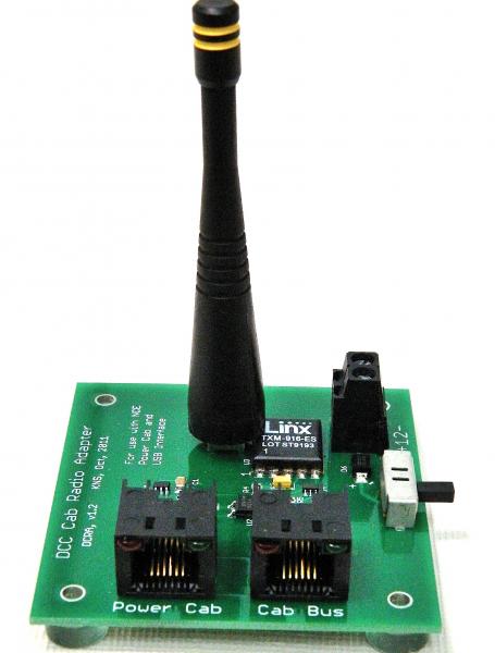
The system I'm evaluating is the S-Cab from Neil Stanton. I want to use my existing DCC sound decoders (mainly ESU Loksound), S-Cab provides the necessary electronics to do this. I would like radio control of a Collett Goods, an 0-6-0 or 2-6-2 (for B-set work), a 14xx (for autocoach work, for this the system will go in the autocoach), and a diesel railcar.
The transmitter (916.5 mHz) uses LINX technology and connects directly to the NCE Powercab (front), and has it's own power supply (terminals at back right) that also powers the Powercab.
Next shot shows the electronic units that will go in the tender. At the bottom is the Lithium ion polymer batter, in this case a 3.7v single cell 500 mAh unit. Next up is the battery power supply control (PBS). The 2 grey wires connect to track power for charging (via the wheels on a live section of track), the brown wires connect to a reed switch that turns the battery on and off. Convenient, as it can be located where required. The reed switch is activated by a magnetic wand. There is another reed switch on the back of the BPS that switches power to the radio receiver/DCC unit on and off. The BPS supplies 12v DC (red/black leads) to the radio receiver/DCC unit (Top). The DCC output goes to the DCC decoder (green wires). I intend to wire this to an 8-pin socket that the decoder will plug into. The aerial is the grey bar labeled AF on the left.
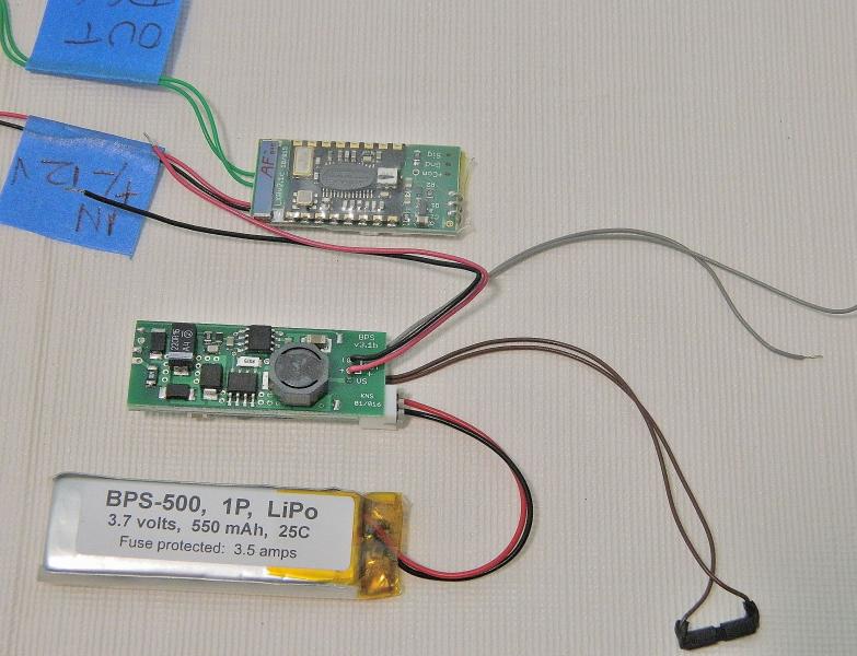
Last shot shows the electronic units next to a ruler - getting these into an 0-6-0 would clearly be a challenge. a 2-6-2 might be a better proposition.

I test fitted the above, they will fit in the tender when those plastic posts are removed, raising the coal load will give enough space for the decoder and speaker. Next up - modification (butchery) of the tender to maximize space, plus some thoughts on how to switch between conventional DCC and radio DCC.
Bottom line with all of this technology - modern 4mm scale locomotives (and 3.5mm scale ones) are just not designed for radio control (many are not even properly designed for DCC!) - the space is just not there. What I would like to convert to radio control and what is feasible may not be the same. Hackery and butchery are the order of the day. The Collett Goods is straight out of the box, "nevah bin used guv", those of faint hearts please ensure the smelling salts are to hand, because what I am about to will void the warranty and minimize any resale value it may have had. No pain, no gain…
©Nigel C. Phillips
Posted

Inactive Member
Max
Port Elderley
Port Elderley
Posted
Full Member
Posted
Full Member
Hi Max,Thanks for going to the trouble of sharing all this, Nigel. :thumbs
Thanks. Having made a decision to go "dead rail" at home I thought spreading the potential of battery power worthwhile. My approach is a bit different to that described by Dave (Davecttr). My criteria are to a) use the existing DCC control equipment, b) use the exisiting DCC decoders, and c) have track charging of batteries. Bit more demanding on real estate inside the loco's than a simple DelTang system, but I get to use the DCC investment I've made over the years. New controller not required. Not strictly 100% "dead rail", but a short isolated siding with 12v DC for charging should do it. And of course no DCC wiring, frog juicers, point/switch modification and the like. Plus I can stop worrying about shorting out a DCC sound decoder in some of the North American brass coffee grinders that have a live chassis/body.
However, you all get to share in those "oh dear", "goodness me", "tut-tut" and "well I never did" moments that will undoubtedly occur along the way.
Nigel
©Nigel C. Phillips
Posted
Full Member
Hi Dave,Don't worry about butchering, if it has to go so be it!
It's never stopped me in the past. The UK models are next to impossible to sell here on eebygum, postage makes it next to impossible to sell them in the UK, might as well do something different with them. Plus it's an interesting challenge to get the electronics inside some of the smaller engines.
Nigel
©Nigel C. Phillips
Posted

Full Member
Cheers
Andy
Andy
Posted
Full Member
Thanks. Did a bit of work on the tender over the weekend, plus had a look at the loco innards. More later.
Nigel
©Nigel C. Phillips
Posted
Full Member
Tender top was cut out with a small fine-tooth saw. I'm working on a coal mound in styrene that will pretty much be level with the top of the sides and go up from there (think hollow mountain). This is one of the old tenders from the ROD 2-8-0 that the GWR used on some Collett Goods. The GWR 3500 gallon tender appears to have the same volume. as it doesn't have the wheel wells. More on that later.
Inside shots. All those posts have been removed or filed flat. I'm leaving the sids of the wheel wells for the moment as there appears to be enough space for the components.
The battery slots between the wells, I'll add some small styrene supports to make sure it doesn't move around. The receiver and BPS will fit either side of the battery. Which just about leaves enough space for a mini decoder and speaker.

Onto the engine. One of those "well I never" moments. Seems I put a decoder in to test run and then put the locomotive away. It's a Digitrax N-decoder, the leads occupy more volume than the decoder. Not sure how much current Bachmann or Digitrax think will be required. "Rip it out, rip it out". I'll replace with a sensible wiring harness (or 2).
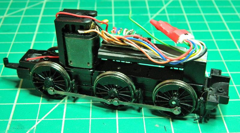
That 8 socket board and supression system also takes up a lot of volume. That will be going as well.
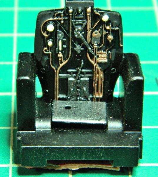
Now I vaguely remember doing this, bit of bling makes the backhead come alive. Just needs some numbers on the dials and gauges.
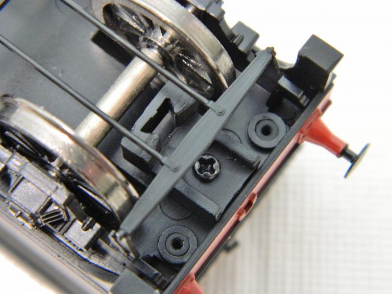
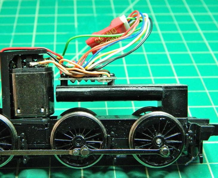
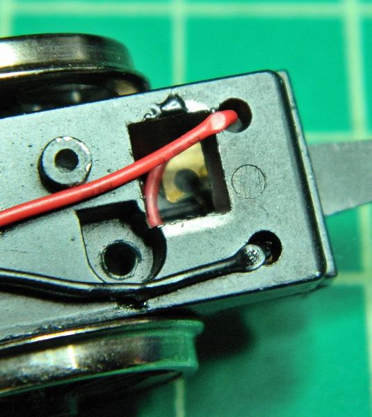
Now this helps a lot. The wipers connect to P/B strips with a couple of rivets at the end to keep them in place. Just the spot for taking charging track power to the BPS in the tender.
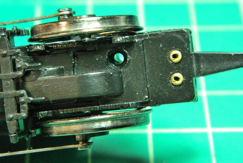
The strips can just be made out inside the chassis. Looks like the factory soldered the leads the wrong way round.
That's it for the moment. Next post will be some thoughts on having a dual system - regular track DCC and radio DCC - in the same engine, with an easy changeover between the 2 systems as required.
SaveSaveSaveSaveSave
©Nigel C. Phillips
Posted

Full Member
Soldering fine wires onto almost imvisible contacts on decoders is just the thing for old eyes like mine ……………..but I hope to learn how to do it.
 cheers
Also, I have had problems with the wipers not making proper contact with the wheel backs in the past. Is there an easy solution ?
'Petermac
Posted
Full Member
Couldn't agree more. Those pads (when they are present) are mighty small and close together in most cases. Which is why I avoid messing about with decoders. One twitch and "there she blows". And no warranty. I like the idea of just using the standard wiring.Following with interest Nigel. :thumbs
Soldering fine wires onto almost imvisible contacts on decoders is just the thing for old eyes like mine ……………..but I hope to learn how to do it.
Also, I have had problems with the wipers not making proper contact with the wheel backs in the past. Is there an easy solution ?
QC on wipers is abysmal. Take some tweezers, bend the wiper out longitudinally and laterally so the head is outside the wheel rim, then bend back longitudinally. Don't do this too many times, otherwise fatigue will break the P/B. Otherwise remove the bottom plate and adjust. I try and use Gibson sprung wipers when feasible.
Nigel
Save
©Nigel C. Phillips
1 guest and 0 members have just viewed this.