Bagnall 0-4-0 Saddle Tank Quarry locomotive
Posted
#222985
(In Topic #12167)

Full Member
Wrightlines 7mm Narrow Gauge White Metal Kit rebuild
Hi All,Change of gears for next year - back to 7mm scale narrow gauge (16.5mm gauge, 2.9 feet track).
Sorting through the spares boxes recently I came across a Bagnall 0-4-0 saddle tank kit, part built, by Wrightlines. Just the job for a small cameo layout of a quarry/chalk pit (which is why I originally bought it). After a bit more searching I came across the paperwork that came with it. And that's when the fun started.
I bought the kit at a 7mm Narrow Gauge Association annual meeting in 2004 in Burton-on-Trent, memorable for the failure of the organizers to get a license for the consumption of beer. Good job there was a pub next door to the meeting place. Bought from the Association trade stand as "part built and complete", I now realize both descriptions would not meet even a lax definition of either. I was going to junk the kit and use the white metal parts for other purposes, when a discussion with John (Brossard) nudged me into getting into O-scale narrow gauge (again). Nothing like a change of pace, and for me O-scale narrow gauge has the advantage of using 4mm scale track.
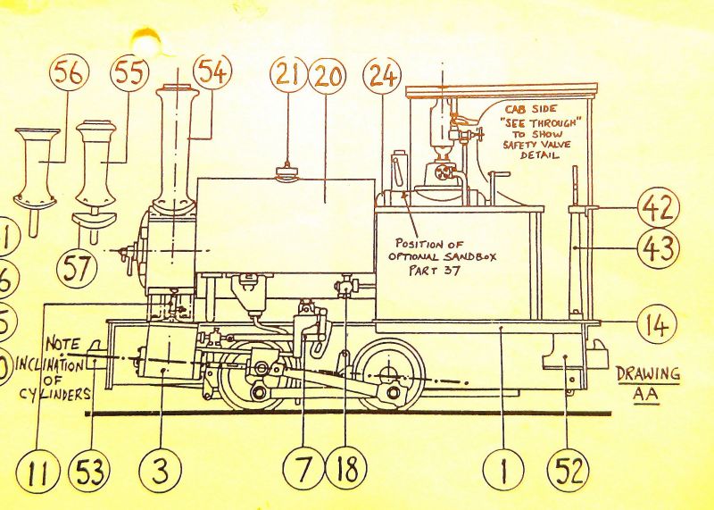
The first bit of paperwork with the kit says that the chassis from a Dapol 0-4-0 is used to mount the white metal body and cosmetic valve gear. The second, clearly much later, describes an etched chassis construction and brass body build. What's in the kit is a dog's breakfast, consisting of an etched and modified chassis (possibly to take an 0-4-2 wheel arrangement), cosmetic valve gear, and white metal body. The body appears to have been built at some stage using solder and epoxy, then dismantled (or more likely dropped), and there are various duplicate bits. Plus a few bits missing, notably the valve gear, and broken (the footplate and cab sides). With the exception of the valve gear rods, all the white metal detail bits appear to be there. One cylinder valve cover is missing, and has been replaced by a styrene scratch build. Most of the broken bits look to be repairable. It came with a Branchlines motor and gearbox, and Romford wheels, so not so bad.
The following diagram was useful for identifying the parts in the box.
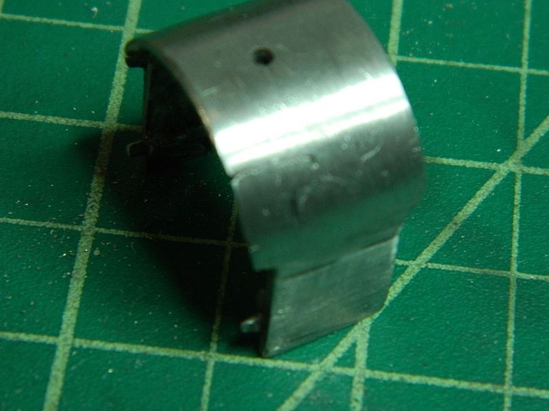
Problem 1 - broken roof stay. I can't see the missing piece in the box.
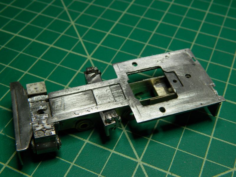
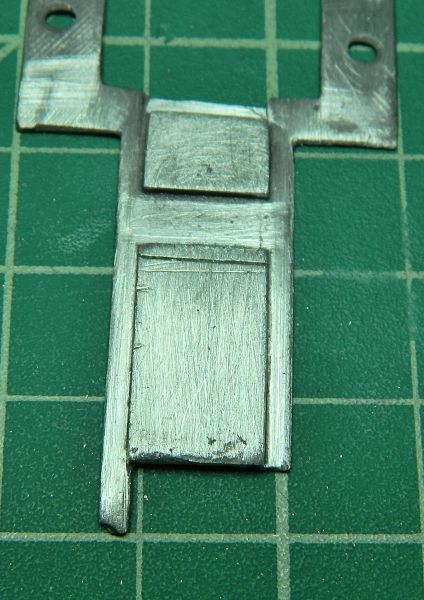
Problem 2. The footplate extension fits under the cylinder saddle, the broken bit is in the box.
Sort of a problem 3. This is either some really poor soldering or old epoxy and what happens when you drop a white metal from 3 feet. Should clean-up OK.

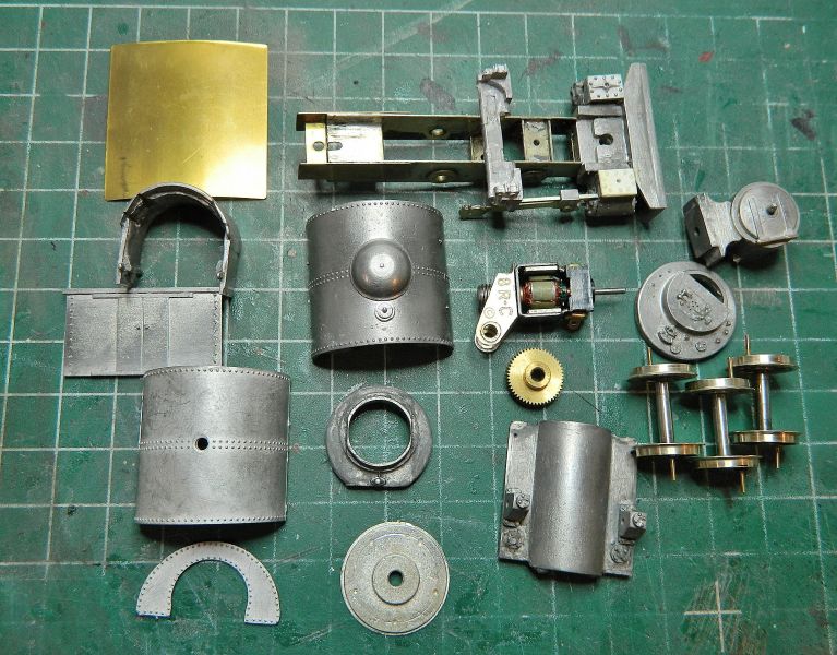
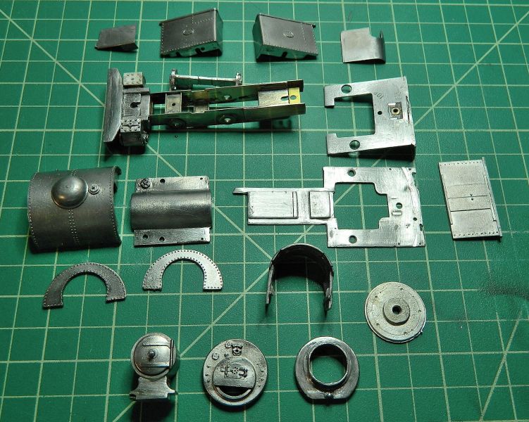
Major bits and pieces. Duplicate saddle tanks, chassis half-built, styrene replacement valve cover, 3 axles (??), minuscule motor and gearbox (probably a 40:1 or even 50:1 ratio). The motor sits inside the firebox.
Close up of dummy valve gear and chassis extension. I hope those top-hat bearings are true and straight.
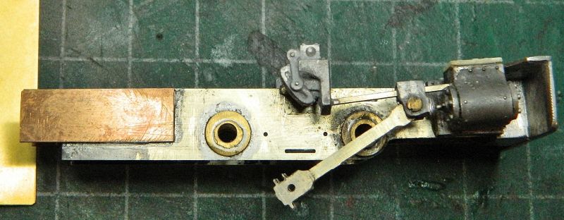
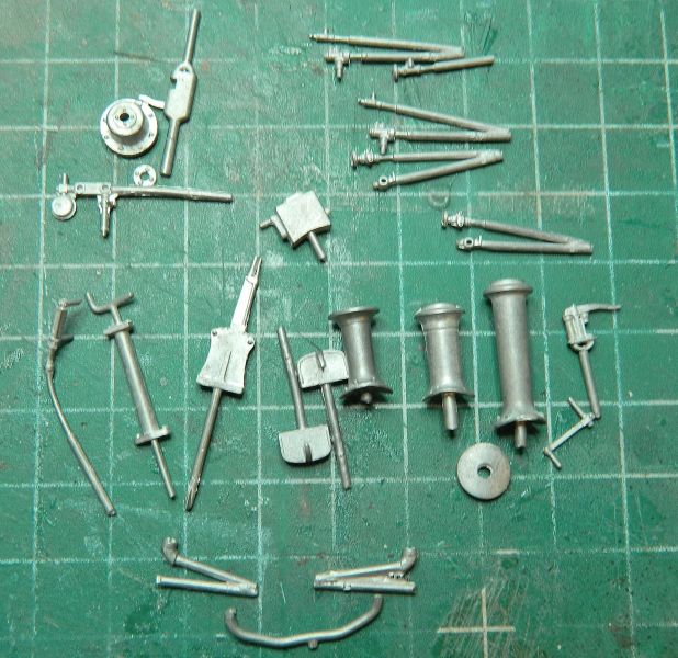
The detail bits I have been able to identify so far. There are a few more that may or may not belong to the kit.
Wrightlines was taken over by ABS models several years ago, spare parts are problematic at best. I think there is enough there to get a model up and running. I've tackled worse porcine ears (but not in a long time). Should be fun.
Nigel
SaveSave
©Nigel C. Phillips

Posted

Full Member
:doublethumb
John
John
Posted
Full Member
3 sets of wheels, two holes. Hmm. The previous owner could have been a tad ambitious.
A dunk of the body parts in paint stripper for a week is probably called for to get rid of any epoxy, followed by a dunk in acetone to get rid of any CA. Then some desoldering. If that chassis is straight, all well and good. If not it's going to be a total strip down. Some measurements tomorrow.
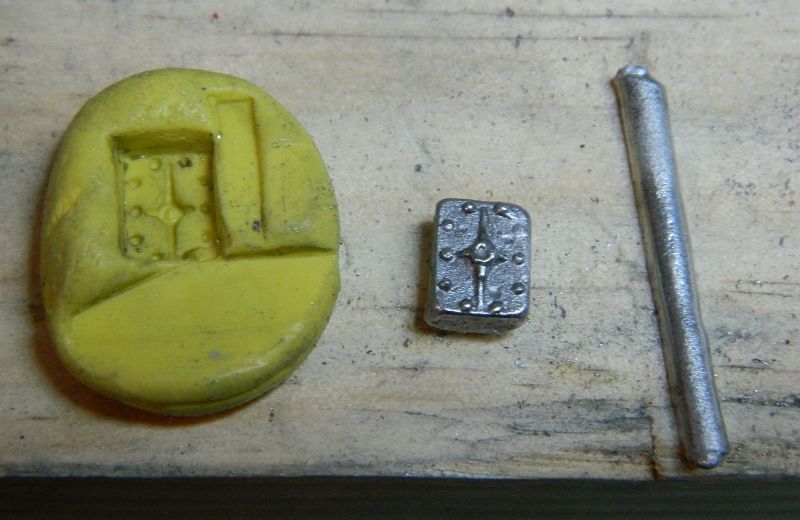
A bit of scraping tonight showed epoxy, CA, and solder. And that's just the assembled chassis, cylinders and valve gear castings. That styrene valve cover is bothering me as well. Perhaps some silicone rubber molds from the white metal one followed by a bit of casting with hard solder is called for.
Nigel
©Nigel C. Phillips
Posted
Full Member
I don't know, I would, as a point of principle, use solder for the structural parts - whitemetal or brass. I use about 355C on my iron for brass (sometimes higher for large pieces) and, 300C for W/M - seems hot I know but the trick is to get and out and make the joint.
For small details I'm not averse to CA.
I like the idea of making parts by copying others. That will be a good tutorial I think.
John
John
Posted
Full Member
What I though was CA is old solder (first builder?). The sections that has been epoxyed on are the motion brackets and their frame across the chassis (second builder?). So rather than a dunk in methylene chloride and methanol for a week or so (with disposal issues afterwards) I'll see if it can be removed with the saw, needle files and the big blade. Plus some delicate work with the iron.
Nigel
©Nigel C. Phillips
Posted
Full Member
Body and chassis has been broken down into the component bits. Turned out to be a combination of solder and epoxy holding it together (mainly epoxy). The only thing I didn't disassemble was the smokebox and cylinder yoke, as they're both square. The upper cab front sheet and sides were tacked on with epoxy (why?), I'll use that in another project (well, at least the front spectacle sheet and half the sides).
One of the interesting things about white metal and solder is that while it is relatively easy to solder components up, it often doesn't work the other way. I had the iron at around 300°, this white metal melts well below that. I resorted to a fine saw blade to separate the footplate from the cab frame after melting a hole at the edge.. A bit of judicious bending straightened out the rear buffer beam. I removed most of the accumulated grime with #150 paper and a fine brass bristle head in the Dremel.
I have found a picture of a slightly later Bagnall with only a veranda, I'll post as soon as I get permission (hopefully) from the copyright owner.
Several repair jobs need to done, see pictures and text.
The "kit". The previous modeler (I'm using that term lightly) had soldered and epoxyed the cab plate/buffer second row right) to the running plate (third row down). You can see what the desoldering did to the edge of the footplate. There is actually no need to use anything other than the 3 bolts to hold it all together (including the cab sides). It's not as if it's difficult to see where the holes are. Getting the valve gear bar off was the most difficult, again it was a combination epoxy and solder. Which ruled out the paint stripper treatment to dissolve the epoxy. And it wasn't straight.
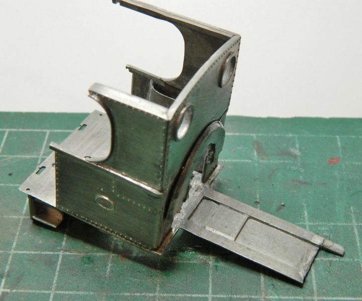
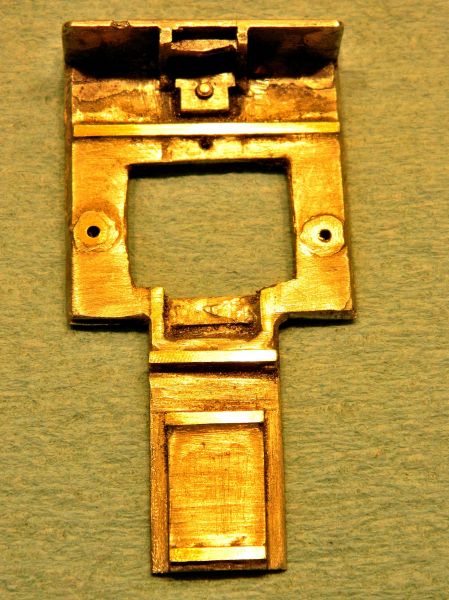
Test fit of the footplate and cab plate showing where the holes line up. Plus that molten edge to the footplate. An obvious repair is in the plans. The Bagnall-Price valve gear yoke cleaned up nicely. That styrene valve cover sticks out like a sore thumb. Off to Michaels tomorrow for one of those paint-it-on silicone mold kits, which I'll use on the good one to make a cast. Some 100° solder should do the trick.
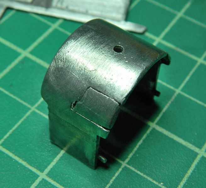
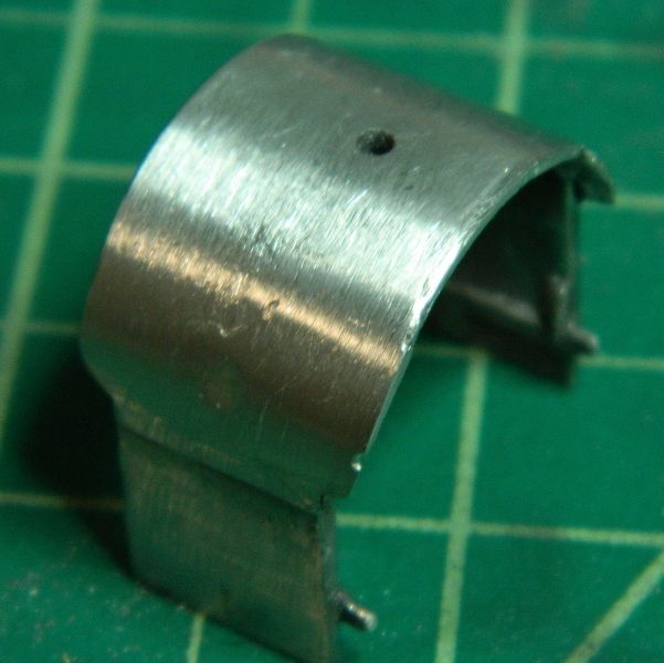
Repair job 1. The missing piece on the end of the frame is attached to the underside of the smokebox with epoxy. If I can get it off I'll solder it back where it belongs, if not a bit of brass soldered on will do. The smokebox is supposed to be attached to the cylinder yoke with a BA screw, allowing for easy assembly after painting and for any disassembly. Not glued to the frame.
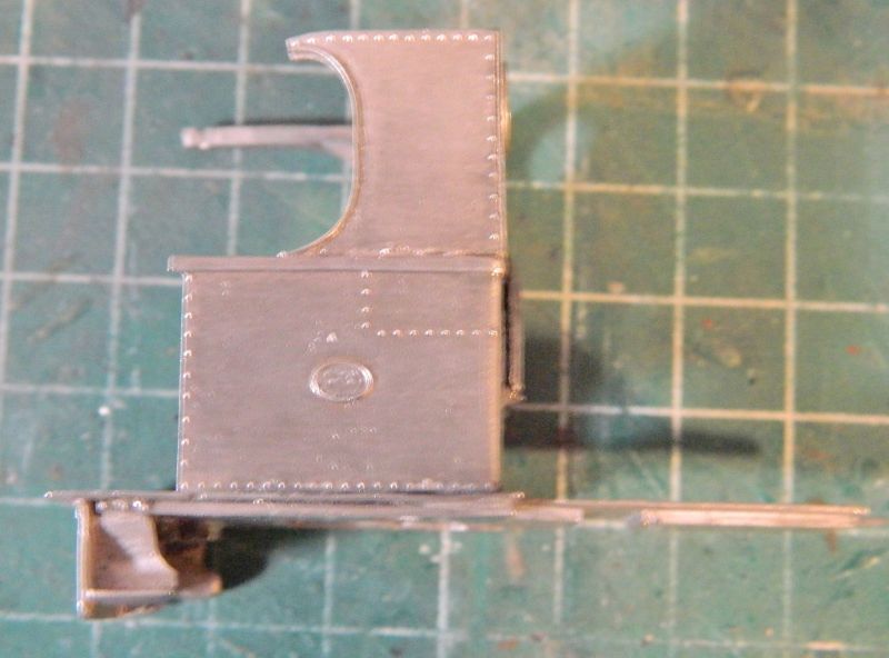
Repair 2. For some reason 2 pieces were cut of the sides of the smokebox and then reattached. They need stabilizing on the inside with some additional solder, and filling with fine filler on the outside after cleaning out the cracks. This part is going to be very visible as there is no front sheet or sides to the cab.
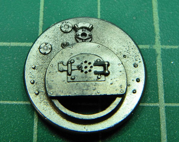
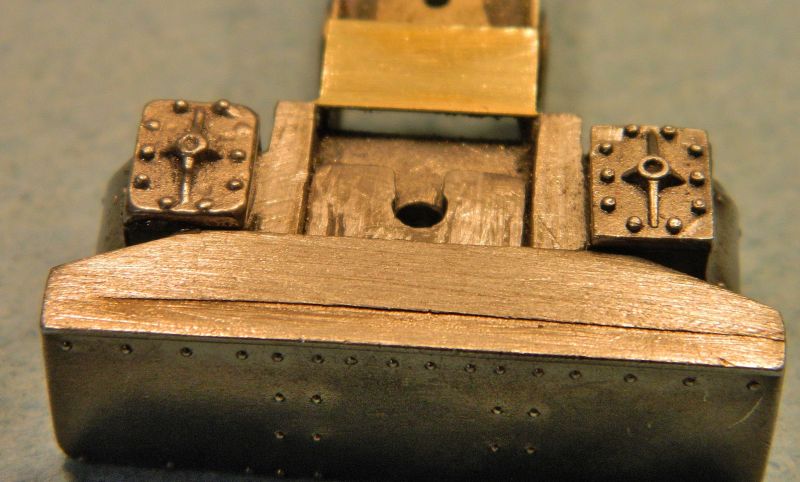
Backhead detail. Not bad for an old model. All of the bits to be added are in the box, so all that needs doing is to drill some holes.
Nigel
SaveSaveSave
©Nigel C. Phillips
Posted

Inactive Member
Max
Port Elderley
Port Elderley
Posted
Full Member
:chicken
John
Posted
Full Member
:chicken??
Nigel
©Nigel C. Phillips
Posted
Full Member
John
Posted
Full Member
Ah, "the most annoying song of all time". I managed tune out when it was going the rounds in the '80's (not hard to do in France and Québec). Hence the ??
Nigel
Onward, upward, hold on, where's the path gone?
©Nigel C. Phillips
Posted
Full Member
John
John
Posted
Full Member
Essentially repairs to the damage done by previous owners (plus my hot iron melt of the cab floor). As some of this work was quite finicky I ordered a temperature controlled iron. Worked a treat, melted the 100° solder, didn't melt the bodywork.
The fancy-smancy soldering station. It's a Kendal, every workshop should have one. 200°-850°, ceramic heating element. I did all the work at 210°.

Repairs to the splits in the firebox.
And t'other side.
My previous white metal melt repaired.
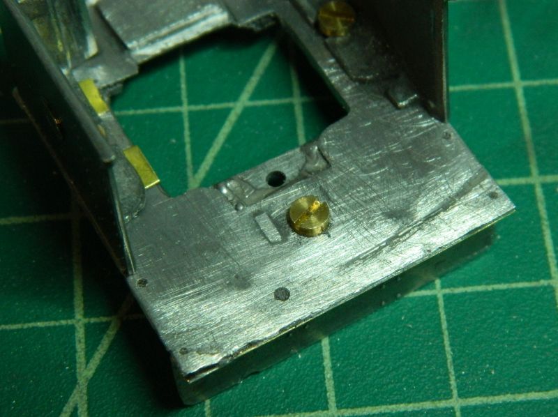
Cab sides attached with nuts and bolts. The cab floor was soldered to the chassis plate.
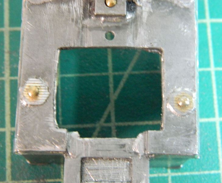
The underside. Brass nuts soldered in recesses with bolts in place. The bolt threads were treated with a 2B pencil to stop the solder sticking.
The silicone putty molding kit came this morning, so I made a mold out of the good valve cover and cast a replacement one using 100° solder. The silicone is food-grade, and good for 250°C in the oven, so it was quite happy with 100° solder. Not bad. I might try a resin cast (or even an epoxy one), as the white metal shrinks when cooling.
Nigel
SaveSave
©Nigel C. Phillips
Posted
Full Member
I concur with your recommendation regarding a soldering station, very useful indeed and mine has transformed my soldering.
John
John
Posted
Full Member
Thanks. It's amazing how a precise temperature makes soldering a lot easier, especially white metal work. I think I'll go with the valve cover casting as is (after a bit of judicious filing), curvy side on the inside it should look OK. I was really pleased with the repairs to the firebox, that turned out a lot better than I expected.
The idea is to get the cab sides nicely in position with the nuts and bolts, then tack solder to keep them in place. The firebox needs to be able to be removed for painting and servicing the motor (it really should be one unit with the boiler/saddle tank/smokebox), I'm still working on that. The back half-sheet has had its locating tabs removed sometime in the past, I have a plan for something a bit better than a plain vanilla butt-joint.to the cab floor.
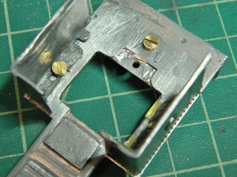
Soldering nuts and making sure the bolts are not soldered up: A 2B or 4B pencil works well, the idea is to get some graphite on the threads, which solder hates. Less messy than oil. The holes were a bit big on the bolt side, I had to remove some metal to get them to line up with the nut holes. A bit of flux and solder filled the holes, the bolts unscrewed as if nothing had happened. The other thing that works well and only takes a few seconds is brass blackening solution - solder will not stick to selenium salts.
Nigel
©Nigel C. Phillips
Posted
Full Member
John
John
Posted
Full Member
which he uses when soldering nuts in
position, the solder doesn't like steel.
Jeff
Posted
Full Member
Good point re steel nuts and bolts. Generally a bit cheaper than brass, but whether solder sticks depends on the flux and the solder. Unless you are unlucky (and it's cheap, low quality steel) lead-tin solder doesn't stick. If it does it's normally a cold joint. Once you start using some of the more aggressive acidic fluxes (phosphoric acid for example) and lead-free solder it can stick. The 100° solder I use is lead-free, I always clean the metals to a bright finish and degrease immediately before soldering using a mild no-clean organic-acid flux (which contain a weak dicarboxylic acid such as malic acid).
It takes 10 seconds to go over the brass threads with the pencil. Pencil leads contain graphite, clay and a bit of wax, so the "non-stick" surface is probably a greasy coat of graphite. A 2B pencil is 74% graphite, 20% clay and 5% wax (the other 1% is who knows what, manufacturing tolerance probably). A 4B is 79% graphite, 15% clay and 5% wax. Bees knees is an 8B, 90% graphite. Expensive though.
Big issue with white metal soldering is the composition (and therefore melt temperature) of the metal. Some of these old kits have very low melting temperatures, almost the same as the solder (in which case use CA and or epoxy). If there is a bit of spare metal with the kit always worthwhile testing it and the solder. Which I should have done of course with this "kit".
Nigel
©Nigel C. Phillips
Posted
Full Member
Bit more work on the Bagnall this morning.
I used that "white metal" casting (100°C solder, which is pretty hard) of the valve cover that I made previously. Filed down to pretty much the thickness of the other one, I used CA to fix as there really wasn't anywhere to get the iron in. Two of the bolt heads need replacing, I have some Archer O scale decal (transfer) ones around somewhere.
I had to put some brass spacers/stiffeners underneath the white metal footplate and cab plate.The wheels fouled it when in position as is, and it was way too bendy for its own good at the "T" junction. Poor design. This leads me to conclude that it really is a mongrel kit, with the white metal body intended for a Dapol chassis, and the nickel-silver chassis from another later kit or even model. Looking at photographs of these engines it's clear that it needs a more substantial footplate (diamond plate), and some angle braces underneath the cab plate. Looks like some rivet punching later today. I do have an "O" scale die set, so we'll see what it looks like.
Nigel
Save
©Nigel C. Phillips
Posted
Full Member
Lots of fettling, adding brass supports, and soldering this morning. The chimney and base were tinned and soldered on at this stage, once the smokebox is soldered to the boiler/saddle tank it won't be accessible. The firebox and backhead was also soldered up, and tacked to the boiler/saddle tank. Finally a dry fit:
One of the brass support bars can be seen above the left front wheel. Cab sides need a bit more fettling at the top, and the nearest one has a gouge that will need repair. The back sheet is held for the moment with a dab of CA, that will get soldered up after I've taken it off and drilled out the holes for the hand grabs.
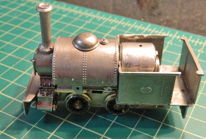
T'other side showing the home casting of the valve cover. Those nubs on the saddle tank need to come off.

Backhead view. Lots of detail to be added after I've finished soldering the body components together. Two more nubs this side on the saddle tank. I may get rid of the dome, as the steam regulator sits on top of the smokebox. The idea is that when the fit is good the cab sides get soldered to the firebox, which then provides 3 bolts to hold the smokebox, boiler/saddle tank, firebox/backhead and cab sides to the chassis. There looks to be another hole in front of the backhead, that will need a brass bracket soldering to the bottom of the backhead. All this will make life easy when it comes to the paint job as the body and cab sides can be removed as one unit. That springy thing at the bottom right is a steel clothes peg with the ends flattened. Used as a holder and heat sink combined when soldering. The motor and gear box sit vertically in the firebox. One of those itsy-bitsy M1.4 screws holding the motor to the gearbox is not in the box. Nor are the smokebox darts. Might have something in the spares box. So much for a supposedly complete "part-built" kit.
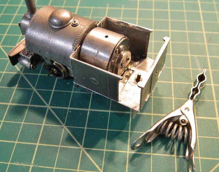
Having looked at the dry fit, I think I'll run this one as an open cab version towing a flat car with extra coal. Pity to hide the backhead detailing and "Christmas tree" valve gear. There is enough room for a driver and mate crouched over the firebox. Slate quarry or cable works, haven't made my mind up yet.
Final fettling and soldering of the body tomorrow. Then I'm on to the running gear.
Nigel
SaveSaveSaveSaveSave
©Nigel C. Phillips
1 guest and 0 members have just viewed this.