Bachmann 57xx
Posted
#252270
(In Topic #13861)

Full Member
EM conversion (not!)
Hi All,I received a Bachmann 57xx last week from the UK (ebay purchase). Good price (1/3rd of the cost of a new one). Externally not bad (it's at least 20 years old) and from the wheel treads lightly used if at all. Missing the rear vacuum pipe, everything else seems to be there. Black and decorated for BR days. Older style wider couplers, that should have been a warning gong! Or three!!!
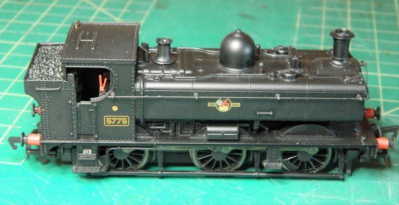
I ran the wee beast on the test track, no real issues, smooth running, some slight clicks but no jerking.
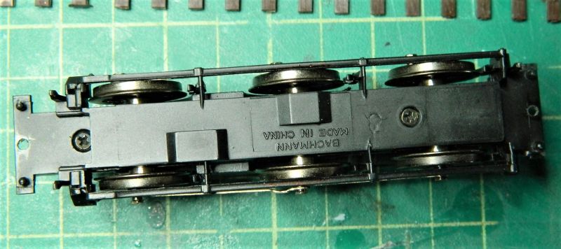
So off with the bottom plate, off with the body and I have the following: A split chassis….
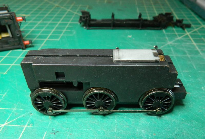
Nice clean chassis halves, everything as it should be, no worn screws or plastic bolts. Hardly any wear on the axle bearing surfaces. This model has seen little if any running. I doubt it was ever run in, as those bearings should be shiny copper. No split half axles either, all the wheel stubs were tight in the carriers.
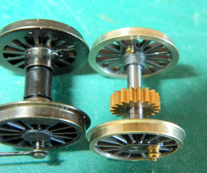
OK, so it's a split chassis model, not the end of the world. DCC-doable with a small decoder and sugar cube speaker in the cab. With the wheels and rods out that's when I realized the Ultrascale EM gauge wheel-set I have was not going to fit. "Well I never!", "Would you believe it!", "Who would have thought it?". (A lot is lost in the translation from what was actually said). 3mm axles into 6mm bearings definitely does not work well. The Ultrascale axles are meant for the later Bachmann chassis design (the split chassis one is a carry-over from when Bachmann bought out Mainline).
Aficionados of the Bachmann 57xx like these older models because of their weight and pulling power. EM conversion is another story.
On the premise that if life serves you lemons, make lemonade, I am looking at the following options:
1. Sell on (limited market over here and in Canada, but you never know).
2. Sell on with a DCC conversion (essentially only the cab space is available, there is a large lump of metal in the bunker as a counterbalance to the one in the tanks).
3. Keep the body, get a Comet 57xx or SE Finecast chassis kit and some Alan Gibson (or Markits) wheels.
4. Keep the body, get a more modern chassis (£££ ouch, ouch, ouch).
5. Get a 45xx and use the wheel-set.
6. Fit the wheel-set into the 56xx I have lying around doing nothing. I know it fits it, and autocoaches/trailers were pulled around using anything from a 517 to a King, why not a 56xx no longer required for coal wagon pulling duty? They were used later in their life for passenger trains and had a mixed traffic classification.
7. Take up knitting.
8. Take up OO again (just joking).
Methinks a decent etched chassis with Alan Gibson drivers set at EM gauge could be the most appropriate choice.
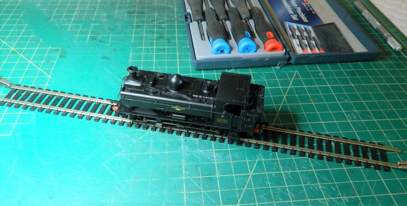
Next photo shows my "test track". This is the only piece of OO track I have. Start voltage of the 57xx was around 3.5V with a bit of cogging, good slow running at 4.5V. It ran with a few clicks when I first tested it, turns out the screws holding the two halves of the chassis were a bit loose. Job sorted. It also needs running in, the rolling bed will have to be used for that.
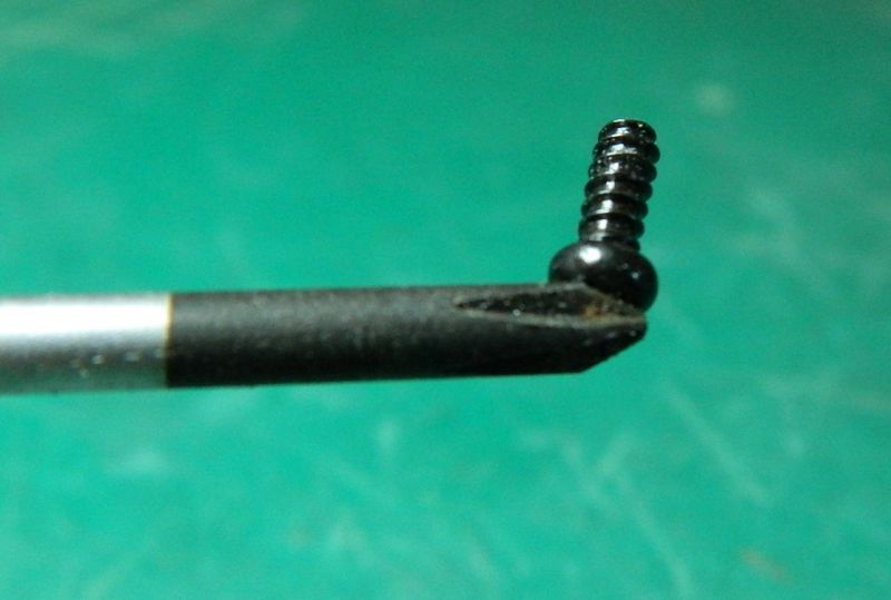
Lastly, I do all the body work using screwdrivers with magnet tips. Enough already of the flying screws never to be seen again! Or even worse later found when expensive replacements have been sourced.
All in all an interesting Sunday afternoon. Never a dull moment.
Nigel
©Nigel C. Phillips

Posted

Full Member
A shame though that such a good looking loco needs so much work to work your railway. At least it’s in capable hands if not passed on to someone else.
Bill
At 6'4'', Bill is a tall chap, then again, when horizontal he is rather long and people often used to trip over him! . . . and so a nickname was born :)
Posted
Full Member
Thanks. Never a dull moment once you move away from OO gauge. I had pretty much decided to sell it on when I realized there is another alternative which is much less expensive in time and money. There is a fair amount of length to those stub axles. I have a feeling I should be able to move them out 0.8mm or so either side (which would give ~0.05mm slop each side) without compromising function or stability. And I just happen to have some 0.8mm black styrene for the required extensions to the chassis sides. plus I also have a Bachmann Spectrum 2-6-0 with a split chassis from a never started On30 project as a tester. Just have to remember to put some datum lines on the wheel and axle for the quartering. If that works I have the pannier and the 56xx. Now where did I put the wheel puller? (Rhetorical question, it's in box 7, tray 2).
Nigel
©Nigel C. Phillips
Posted

Full Member
I was thinking you might be able to get someone to run up a set of shell bearings …. :roll:
Lovely looking loco. :thumbs
'Petermac
Posted
Full Member
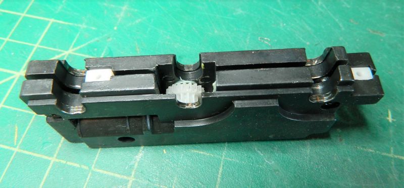
I do have a small hobby lathe. The "bearing" on these split chassis' is a thin layer of copper alloy, probably around 50 microns thick. The stub axle is integral with the wheel, so swapping it for a longer axle is not on unless I sleeve the stubs (with two internal diameters) and cut new bearing holes. Which of course removes the copper bearing surface. Which then means either casting white metal ones in situ and drilling them out (something my father-in-law taught me how to do) or using copper alloy tubing cut in half and soldered to the chassis. Which I definitely will not do given the witches brew of a flux required. Definitely not equipped to do white metal bearing casting. What is really required are longer sockets for the stub axles. They are done in nylon or delrin, doable on the lathe but I do not have an indexing jig, essential for cutting the gear on the center axle. I could of course get them done using 3D printing.On
After all of this it would probably be more economical to buy a new one!
Much simpler just to slide the stub axles out, and put shims and some loctite or CA in to keep them out. I test ran the Bachmann USA chassis this afternoon, worked fine, fingers crossed there is enough meat on the UK axles to regauge them to 18.2 mm. I will find out this evening.
The other problem is of course the body shell, which like many other UK models is scaled below the footplate for HO. After a quick inspection I suspect the wheel wells and the external brake rods will require fettling. Easier to tell after regauging.
Nigel
©Nigel C. Phillips
Posted
Full Member
Success - currently running in on the roller bed. Pictures tomorrow. As I suspected, the middle axle wheel arches will need fettling, as will the brake rods.
Given the BR black livery, an early 1950's minimalistic layout is being contemplated. .
Nigel
©Nigel C. Phillips
Posted
Full Member
Bill
 Last edit: by Longchap
At 6'4'', Bill is a tall chap, then again, when horizontal he is rather long and people often used to trip over him! . . . and so a nickname was born :)
Posted
Full Member
All done by 9:00 p.m. I used the following schedule: Fresh lube on the axles, 15 minutes at 30, 50, 75 and 100% power (4-12V DC), alternating between between forward and reverse at each setting. Note 4V, not 3V, start voltage is 3.1V. This is a PWM power pack, so any notions of actual voltage are relative.
Strip down today, sort some shims, then do the DCC conversion. Some photos when I get on the computer later this morning
Nigel
©Nigel C. Phillips
Posted
Full Member
Some photos following the regauging. Plus some of the issues that are often encountered when re-gauging OO locomotives to EM (or even worse P4) due to the change in scaling required to match the underscale gauge. .
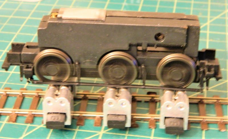
1. Wheels re-gauged and the bottom plate back on. It's a pretty tight fit for the external brake rods. The center axle wheels are actually in contact, the others not. The rods are integral with the plate and the brake shoes. so re-spacing them out a tad is going to be a PITA. Hopefully I can get away with fettling, although the brake shoes could do with moving out to be in line with the wheel treads. Perhaps a piece of black styrene strip glued on the outside of the rods before fetting might be advisable.
2. Closeup of the center axle/wheels. The actual area that needs thinning is quite small.
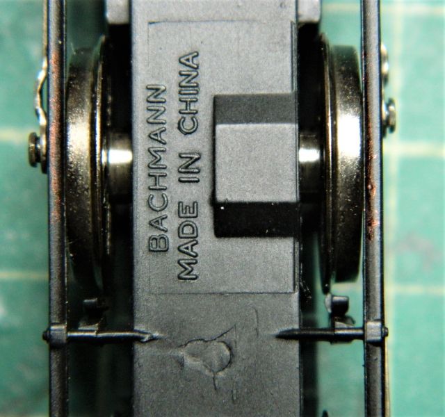
3. For some reason only the center axle wheels and rod bolts are in contact with the body shell. The red indicates those areas that will need removal. I also have a bit of wiggle room in the gauge due to the tread width, so that can be reduced slightly as well.

5. On the rollers in reverse at 12V DC nominal after 2 hours running in. Track is Markway/SMP code 75 EM gauge flextrack. Rollers are from Bachyrus ("Locomotive Running Stand"). I expect better running when the friction from the brake rods rubbing on the center wheels is removed
Nigel
©Nigel C. Phillips
Posted

Full Member
1 guest and 0 members have just viewed this.