Glen Ogle control panel.
Posted
#185540
(In Topic #10428)
Full Member
How I set about designing and building a control panel for my Glen Ogle layout.
My Glen Ogle layout was originally to be controlled by radio control, and to this end, no track wiring was installed other than the five point motors. I found though, that the method I had devised for the radio control of the layouts locomotive stock, which was for the radio receiver and battery, to be installed in a permanently coupled trailing carriage for each loco, so that I could use a big enough battery for an exhibition day of running, without constant re-charging of the batteries throughout the day. But the gradient of the Glen was to prove too steep for the loco's Kato motored bodies adhesive power, and slipping was common. So, until I could find a way to incorporate more weight into the three D printed loco's I was going to use with the radio control, I decided to use my fleet of Lilliput loco's, and wire the layout for analogue cab control.To retrospectively wire a fully scenicised layout was not a task to be undertaken lightly, but hey-ho, needs must, and this is the account of that task, starting with the layouts mimic diagrammed control panel.
I decided to wire the layout with a cab controlled analogue system, using a central control panel, showing the layout diagram, picked out with LED's, point control using DPDT ( double pole double throw) switches, operationally wired using the so-called one wire system, (Which is actually a two wire system in reality) which uses 2 diodes and a capacitor to each point to throw the switch blades, and at the same time as switching the point blades, indicate on the track diagram by colour changing LED's, which way the points are accessing, using the second pole of the DPDT switch.
This spare pole of the DPDT switch could be used as a frog polarity switch, but I have decided to use it as a point route indicator on the control panel, and if I have to wire for frog polarity switching, I'll fix some point operated switches adjacent to the points.
The control panel is constructed as follows.
First the track diagram was drawn out and copies made to allow me to fiddle with section breaks etc. then one copy was protected by a laminated cover to be used on the control panel. This was not entirely successful as the laminated sheet took on a wavy look which is purely the lamination process, and not my crap drawing of straight lines.
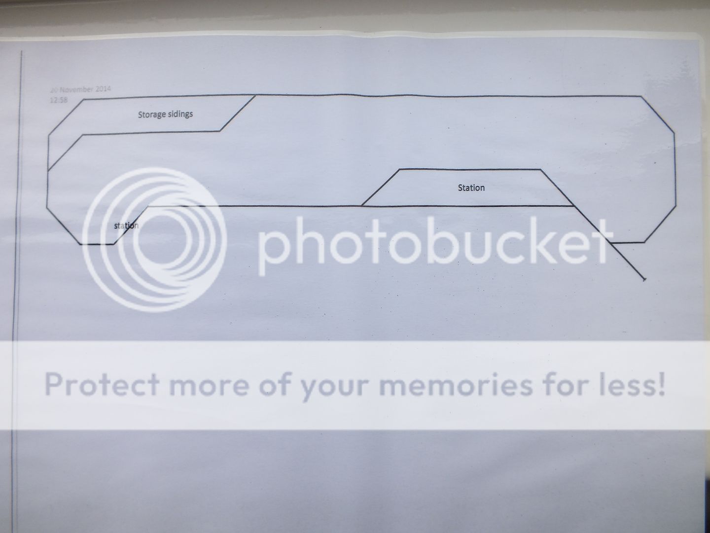
The basis of the panel was a plywood box which originally contained a selection of water colours, and made an ideal A4 size base to house all the electronics and switches that could be mounted on the mimic diagram with all the works hidden inside the box.

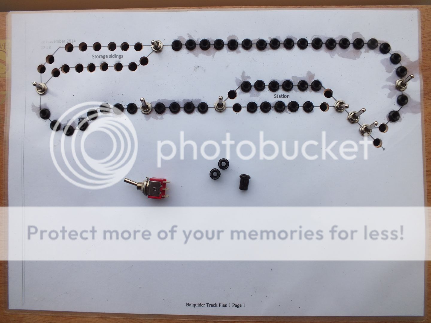
The diagram was glued to the box lid, and all the diode positions drilled and fitted with the 3mm diode holders, and the five DPDT switches fitted at the point junctions, with a further four DPDT switches fitted at the four track feed positions.
The darker grey stains around some of the diode plastic mounts is where I used some very thin Cyano glue to secure the diode mounts in place and the glue ran into the paper diagram inside the lamination cover.
The picture below shows some of the wiring components, the DPDT switch, the 3mm plastic diode holders, the pre-wired single green diodes which came mounted with a suitable resistor and tails for 12 volt operation all ready fitted, and the bare twin colour, green/red three connection diodes, which had to have a resistor fitted to the centre common and wiring tails fitted. These will be mounted at each point divergence, and will show green for the selected route, and red to the unselected route whichever the DPDT switch position is selected.
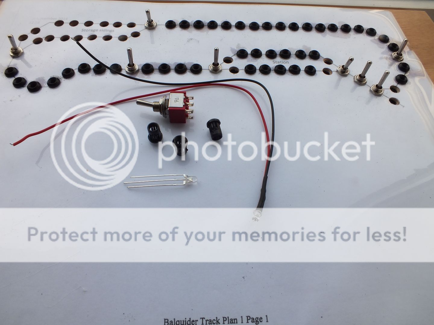
The more Eagle eyed reader will have noticed at the base of the track plan sheet, the reference to Balquider , this is because when I came to save the drawing to computer memory, I had a mental block and instead of typing in the Glen Ogle layout name, I typed in Balquider, which is the name of the junction station back down the line, on the Calendar and Oban railway, upon which this model, Glen Ogle, and my previous loft layout of the Balquider Junction, which I had modelled as an EM gauge layout many years ago, are based Doh. ::)
That'll do for now, I have to take more photo's before the next episode.
Regards,
BrianT.
 Last edit: by gtmspyder
Posted
Full Member
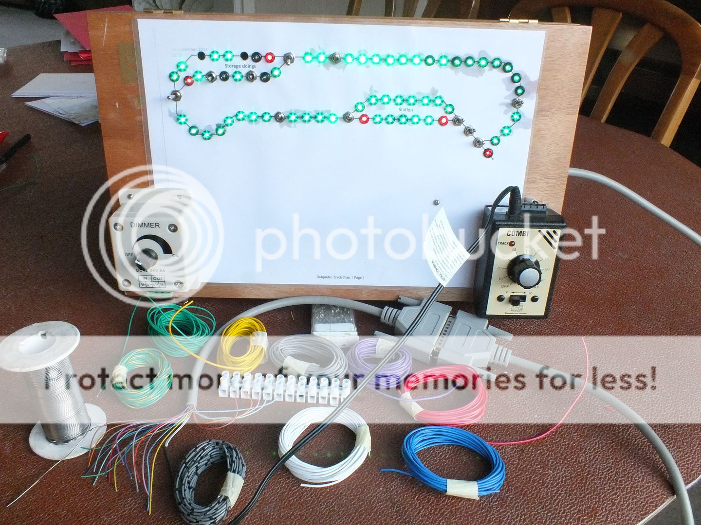
To a view of the control panel as it stands today, along with sundry wiring paraphernalia.
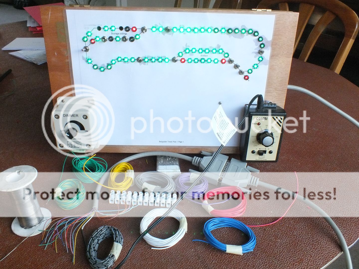
You can see from the above, most of the LED's are now in place and are lit. The power for all this is supplied by the Gaugemaster controller
for the loco's, points and LED's.
The Gaugemaster is held to the control panel with adhesive Velcro pads, and feeds the track 12v DC, via the four DPDT section switches, and the LED's via the smoothed 16 volt ac supply and the LED voltage dimmer control, fixed solidly to the control panel's opposite corner.
You will also note the 25 core cable and "D" connector which carries the electrics from the panel to the layout, I have cut the double ended, male/female plug terminated cable to leave a long tail that is terminated at the cut end, within the control panel box, so that the control panel can be moved around and will be plugged into a gender related socket on the layout, which can be duplicated at other positions around the layout to allow front or rear control as required by circumstances.
The short cut off end will eventually be used as a baseboard joint inter connector, again with a gender related plug/socket fixed to the baseboard.
The number of cables required to feed the various functions along the layout, will be paralleled along the length of the layout to allow the control panel to be plugged in at the various positions required.
You may note a white chocolate block connector temporarily connected to the short splayed out ends of the 25 way cable, this is so I can test the various cables for power carrying capacity and the various colour coding of the cores much easier than crawling under the baseboard trying to identify the colours on the rather thin, 7.02 cabling.
Regarding the current carrying capacity of this cabling, I have no problem with the power delivery to the loco's, and the points are thrown with ease.
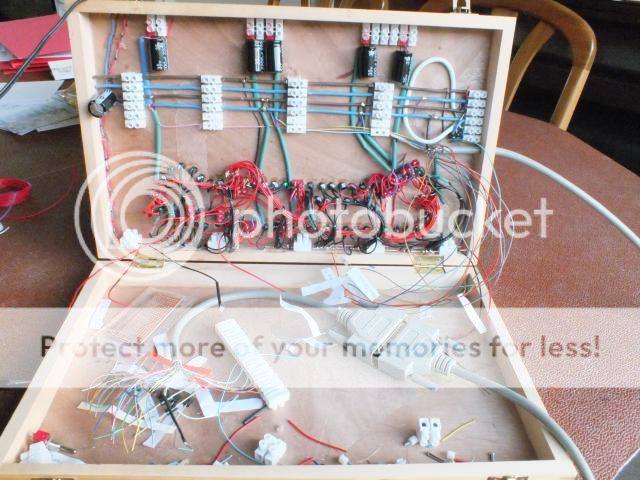
The inside view of the control panel, shows the plethora of wire associated with all the functions I am incorporating.
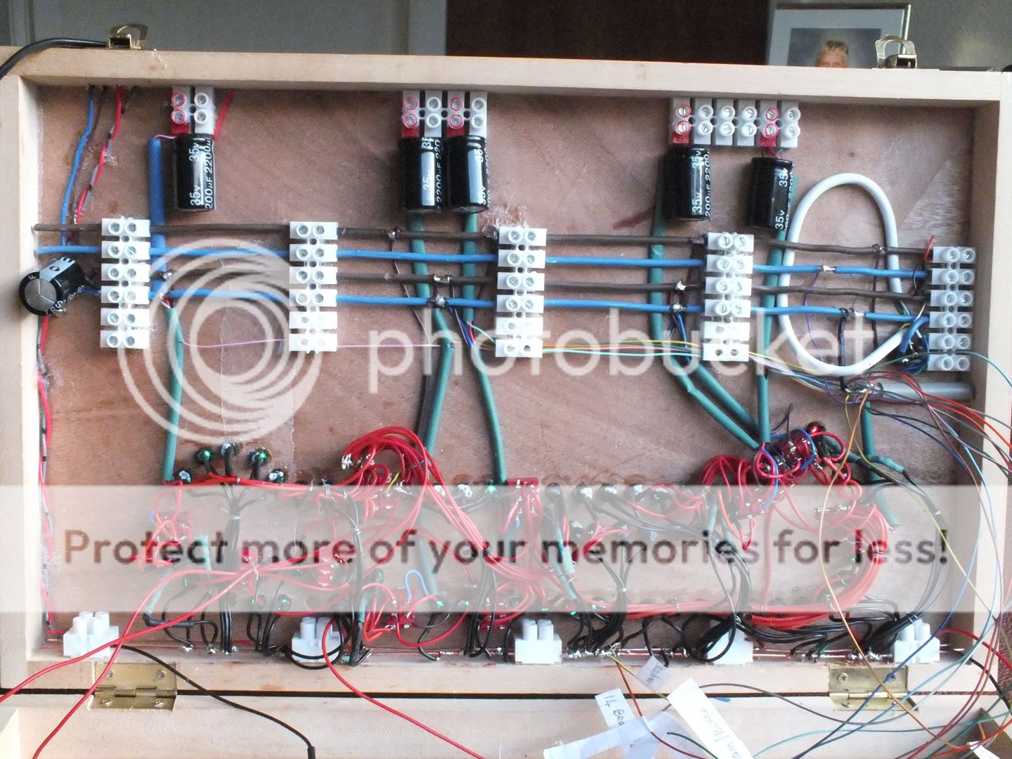
The layout shows a series of bus bars across the control box, the supports for these are cut from the white chocolate box connectors glued into place, the bus bars are from 2.5 mm cable stripped out of twin and earth mains cable.
At the bottom of the picture, the outer coloured sheathing has been stripped from these two bus bars to bare copper, because of the number of soldered joints that have to be made for the LED feeds, and are fed from the smoothed 16v Gaugemaster supply via the dimmer control, to protect the diodes from any overvoltage, despite there inbuilt resistors.
Next up above the many diodes, are a series of six gang chocolate blocks which support from the bottom up:-
The first two of the blocks have there copper connectors cores removed to allow any of the 25 way feed wire cores to be supported from left to right without fear of any shorts between cores during there travel from left to right across the control box, to there destination circuit point.
The middle two of the six block carry blue and brown insulated bus bars which have a 2,200 Mf capacitor across one end, and the positive/negative outputs from an encapsulated four diode rectifier at the other end, fed from the 16v ac output of the Gaugemaster controller, to give a 20v smoothed dc feed to the point motor circuits, which is required for the so called single wire point motor operating circuits,, which have for each point motor a 2,200Mf capacitor and 2 diodes in parallel back to back to operate the two point motor coils using DPDT switches, which means that the motors have permanent lives to the coils without burning the coils out.
(I take no credit for this methodology of point motor operation, this was found for me by Hugh Norwood, from a posting on one of the forums. Thank you Hugh).
To jump ahead of myself, you can see along the top of the picture, the five 35v 2,200 Mf capacitors, fixed in place again, using the chocolate block connectors to hold the capacitors, and accept the bus bar via DPDT positive feed, and the on-going switched wire feed to the back to back point motor coil mounted diodes, hence the term "single wire" feed, although the two other ends of the point motor coils are connected to a common return, which in turn is connected to the negative bus bar back at the control panel, thus technically a two wire operation for the points.
To return to the bus bars, you do remember them don't you?, sorry, any way the top pair of blue and brown bus bars, are connected to the Gaugemaster 12v dc output, and feed the track via the four DPDT section switches, placed around the circuit diagram..
All the outputs are fed via the 25 way "D" plug cable to the base board.
A closer view of the internals.
The loop of white 6 core cable alarm cable, is the link to the Velcro mounted Gaugemaster, to allow it to be lifted clear of the fixing position should this be required at some time.
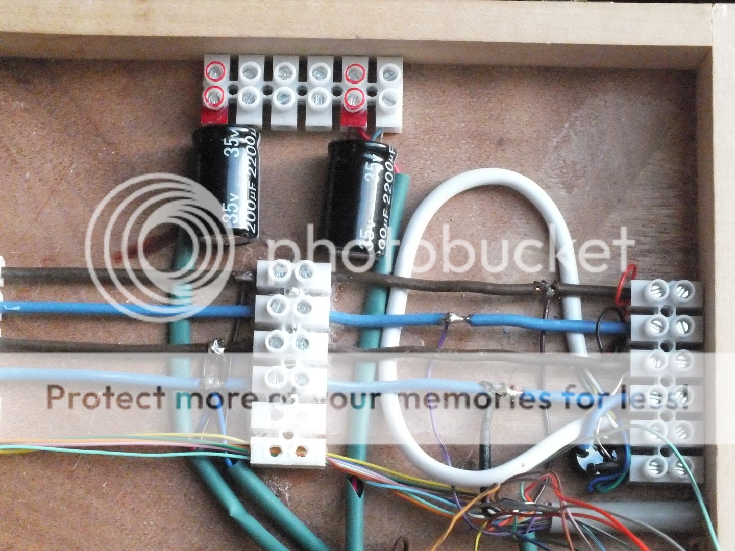
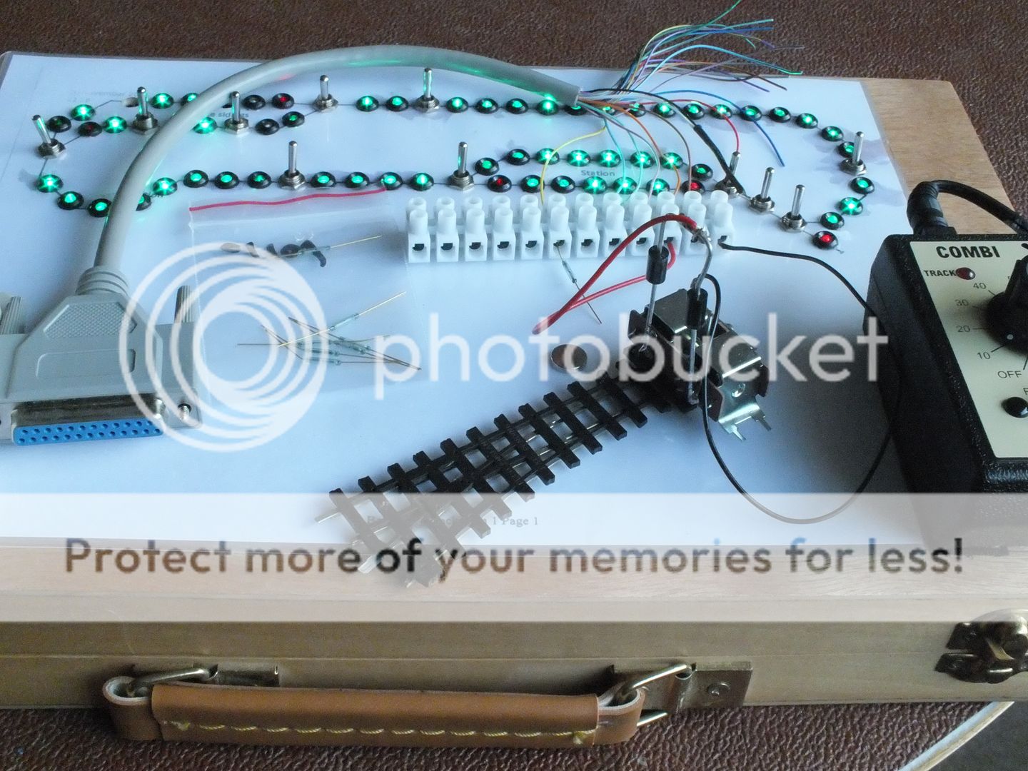
This view shows the short end of the 25 way multicore cable, connected to a length of chocolate box connectors so that I could test each point position operation, with the temporarily wired Peco point and motor, which also shows the two diodes connected back to back across one end of the motor coils, with the red positive feed connected to the diode connection point. the black wire links the two point motor coil free ends to the circuit negative. Each circuit point switch was connected and tested in turn.
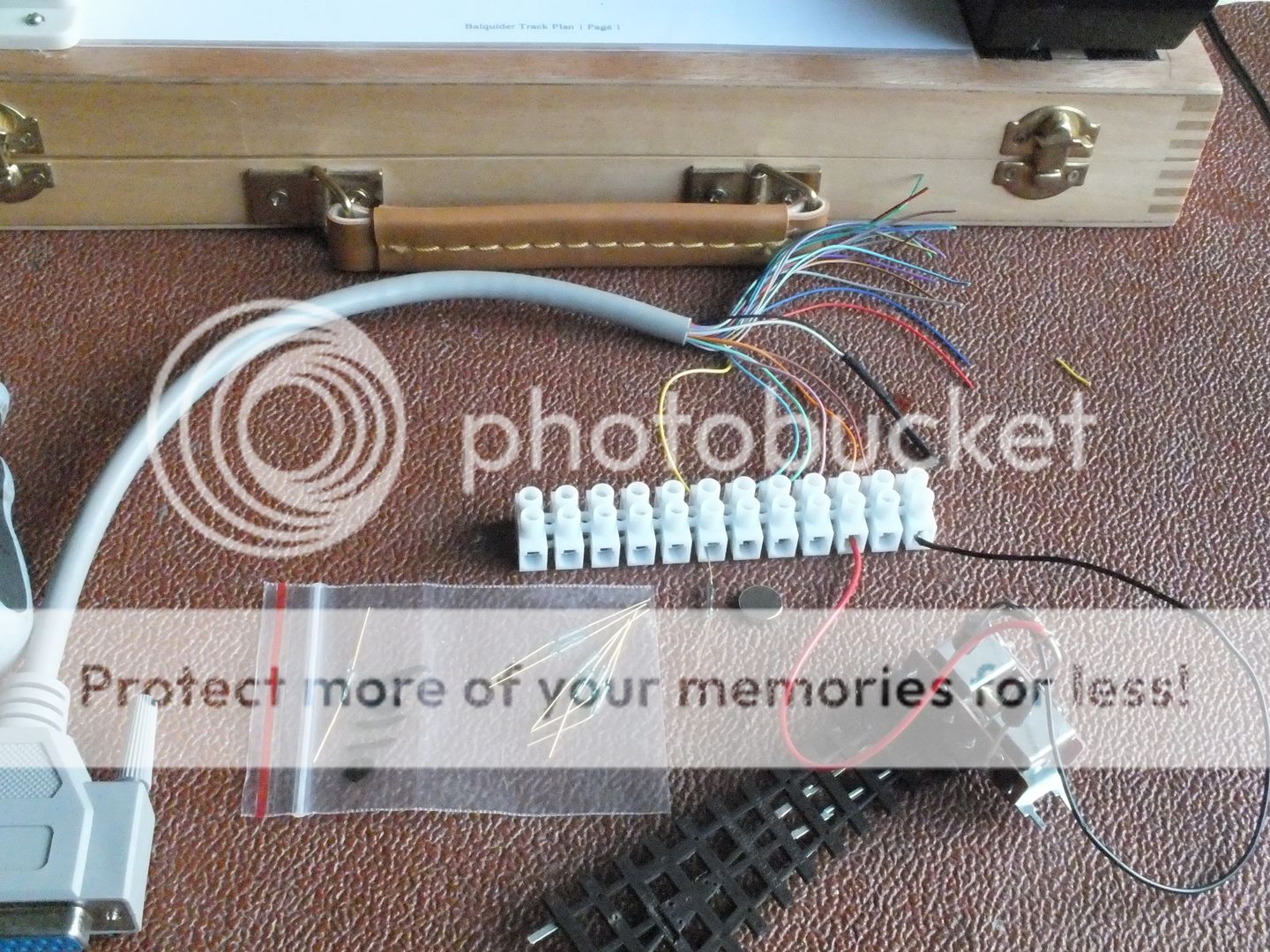
This picture shows the same components against a different back ground to perhaps make it clearer, and also shows, the reed switch and magnet components, which will be used at the rear of layout double tracked train storage area, to detect trains held in short sections off scene, which will be released one at a time on the down and up travel as required. This facility has been wired, hence the yellow wire shown connected to the single test reed switch, but awaits the single pole, push to make switches yet to be fitted in the holes currently left blank on the circuit diagram.
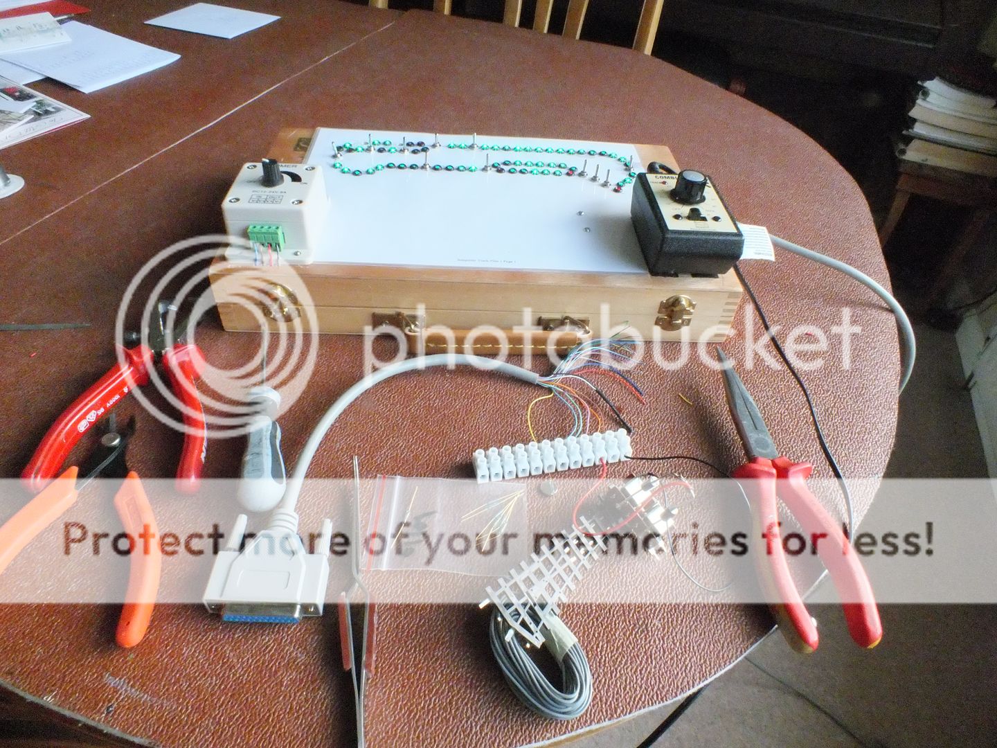
And finally for tonight, a picture showing components and tools used to produce the control board, and my wife's work in progress Christmas card list and assembled cards.
Regards,
BrianT.
Posted
Site staff

Ron
NCE DCC ; 00 scale UK outline.
NCE DCC ; 00 scale UK outline.
Posted
Full Member
The Green LED's are lit when that section of the track is able to receive loco control power.
The LED's adjacent to the points change from red to green to show which route the point has selected.

And not yet shown wired, the storage sidings to the left rear on the track plan, have two dead sections per loop between points, one pair in the loop for right hand rotation trains, and one pair in the adjacent loop for left hand rotation trains. The dead section will show red if occupied by a loco or train, held in store, which will turn to green when a normally open push button is depressed, to allow the stored train to move forward.
The detection will be by reed switches set between the track.
So at the start of a sequence, the layout can have four trains made up and available, two for clockwise rotation of the layout, and two for counter clockwise rotation.
The anticipated sequence of events for one operating session is:-
All track as viewed from the front is empty.
One button on the anti-clockwise storage section is pressed, allowing a train to enter the viewing side, and proceed to or through the bottom left hand station, known as Lochearnhead, head up and over the viaduct, and enter the up, anticlockwise loop of the top station, known as Glen Ogle.
While this is happening, the second storage button on the anti clockwise loop storage is pressed, and the second stored anti-clockwise train moves forward into the vacated loop, automatically stopping, and leaving the rear anti-clockwise loop vacant.
The first button of the clockwise storage section is pressed, and a train will leave it's storage and proceed off scene, up the back of the layout to appear on scene to the right of Glen Ogle station, and enter the clockwise loop of the Glen Ogle station.
During this sequence, the second clockwise storage button is pressed allowing the second clockwise train to move forward into the just vacated clockwise storage section and come to an automatic halt, leaving a clock wise loop vacant and ready to accept a train coming down the front and over the viaduct, through Lochearnhead station, and into store, ready for the next sequence.
The anti clockwise train still at Glen Ogle station, can continue it's perambulations, around the top loop, and down the rear off scene, until it enters the vacant storage loop where it will come to an automatic stop.
And thus the sequence can continue, ad-infinitum.
Ultimately, the unused point at the top right of Glen Ogle will come into play, if I ever build the extension down to Killin and Loch Tay, but that is a story for the future.
I hope that helps.
Regards,
BrianT.
 Last edit: by gtmspyder
Posted
Site staff

Understood Brian but surely only need one LED in a section then ? Especially if each section was a different colour on the panel .Hello Ron.
The Green LED's are lit when that section of the track is able to receive loco control power.
Regards,
BrianT.
Ron
NCE DCC ; 00 scale UK outline.
NCE DCC ; 00 scale UK outline.
Posted
Full Member
All I can say in my defence is, I like complications, and devising and executing circuitry, all be it of the simple none electronic sort.
My electronics knowledge is of the kind, that allows me to assemble from a circuit developed and presented by others cleverer than myself, and some of the times it actually does what it's designer intended.
Other than that, I claim the first amendment, and fall back on the, "It's my railway etc.".
Kind regards,
BrianT.
 Last edit: by gtmspyder
Posted
Full Member
Regards,
BrianT.
Posted
Full Member
I'm intrigued by your use of the 25 way cable connecting panel to layout - do you have any idea of what current it will carry ? I could have a use for just such a thing but using ribbon cable. On the same lines, what size of choc block have you used ? I find it quite difficult to connect small bore cables using choc blocks - the screw clamp tends to either cut through the wire or to "walk" it off to one side as you tighten the grub screw……..:roll:
'Petermac
Posted
Full Member
- Darius
Posted
Inactive Member
I see a latent candidate for Railroad & Co., before me.
Max
Port Elderley
Port Elderley
Posted
Site staff

I hope you did not take any offence at the last post Ron, none was intended.
Regards,
BrianT.
None taken Brian,
as you say "Other than that, I claim the first amendment, and fall back on the, "It's my railway etc.". "
If it works for you, go for it !
Seeing other options in this hobby, helps in many ways.
Ron
NCE DCC ; 00 scale UK outline.
NCE DCC ; 00 scale UK outline.
Posted
Full Member
As far as I can ascertain, 7.02 cable is equivalent to American 22 gauge.
A single 7.02 wire can handle 5A.
Bunched as 27 cores, this drops to 2A per core.
I agree that the choc blocks are not ideal. The ones you see in my control panel are 5A, I know there are some 2A versions which would be better, but best of all are the kind that have a leaf of flat copper between the fixing screw bottom and the cable to be trapped, but if you can find them, they are much more expensive to buy.
What I tend to do is twist the bared copper coils and then bend them back on themselves, and apply solder to the wires to thicken them up even more.
The only downside to this is if the soldered wires suffer movement at the exit to the choc block terminal, the soldered wires can break off due to there stiffness.
Another dodge to alleviate that aspect of the made joint, is to bare the wire core, bend it back down the outside of the insulation, twisting the bared cores around the outside of it's own insulation, and trap this thickened core, insulation and twisted wire, under the choc block screw.
I would only ever use this method on low voltage low current joints, as in model railway wiring.
I hope this answers your question Peter and helps.
Thank you for showing an interest in my modelling.
Regards,
BrianT.
R
 Last edit: by gtmspyder
Posted
Full Member
Is the candidature for Railroad an Co. catching, have I caught it, and what is it, I'm intrigued. LOL.
Kind regards,
BrianT.
Posted
Inactive Member
It is also very addictive, so beware of it. :It's a no no
The good news is, if you haven't heard of it - you probably haven't caught it. :thumbs
If you have had your shots, go to www.freiwald.com Do NOT go alone . . . . .
Max
Port Elderley
Port Elderley
Posted
Full Member


Thanks for the info on the wires - I use 7.02 for my droppers. A nifty tip about winding the wire back on itself before clamping in the choc block - never thought of that although I have used your soldered method - and experienced the same problems regarding breaking at the solder joint …………….

Clearly the 2amp multi-core is too light for board to board connections - but then I don't need 27 cores ………………6 or 8 would probably do me. :thumbs
'Petermac
Posted
Full Member
I use 6 pin chassis plugs and sockets to connect my control panel which I get from Thunderpole Mic Plugs / Connectors | Amateur Radios | THUNDERPOLE
They will take wire up to 24/0.2 so should be ample for your needs.
Apologies for hi-jacking your thread Brian.
Regards,
Trevor
Trevor
Posted
Full Member
They look the jobbie for me - and dirt cheap to boot. I suspect the "small order surcharge" that's been talked about on another thread will push them up to around a fiver each ………………………
 :roll:
'Petermac
Posted
Full Member
I all ways try to be polite with thanks to fellow members.
Kind regards,
BrianT.
Posted
Full Member
No. This supplier does not make a surcharge for small orders. They are exactly the same things that Maplin charge 3 times the price for - assuming Maplin actually have them in stock that is.:twisted:
 Last edit: by Chinahand
Regards,
Trevor
Trevor
Posted
Full Member
You may remember we last saw the control panel it was in this state.

I have moved on a little and finished mounting the diagram LED's and the midsection isolating release push switches, two in each leg of the rear storage roads, and one in each leg of Glen Ogle passing station. These switches are a simple press to make type which supply the track power to isolating sections just long enough to hold and accommodate the engine of any passing loco.
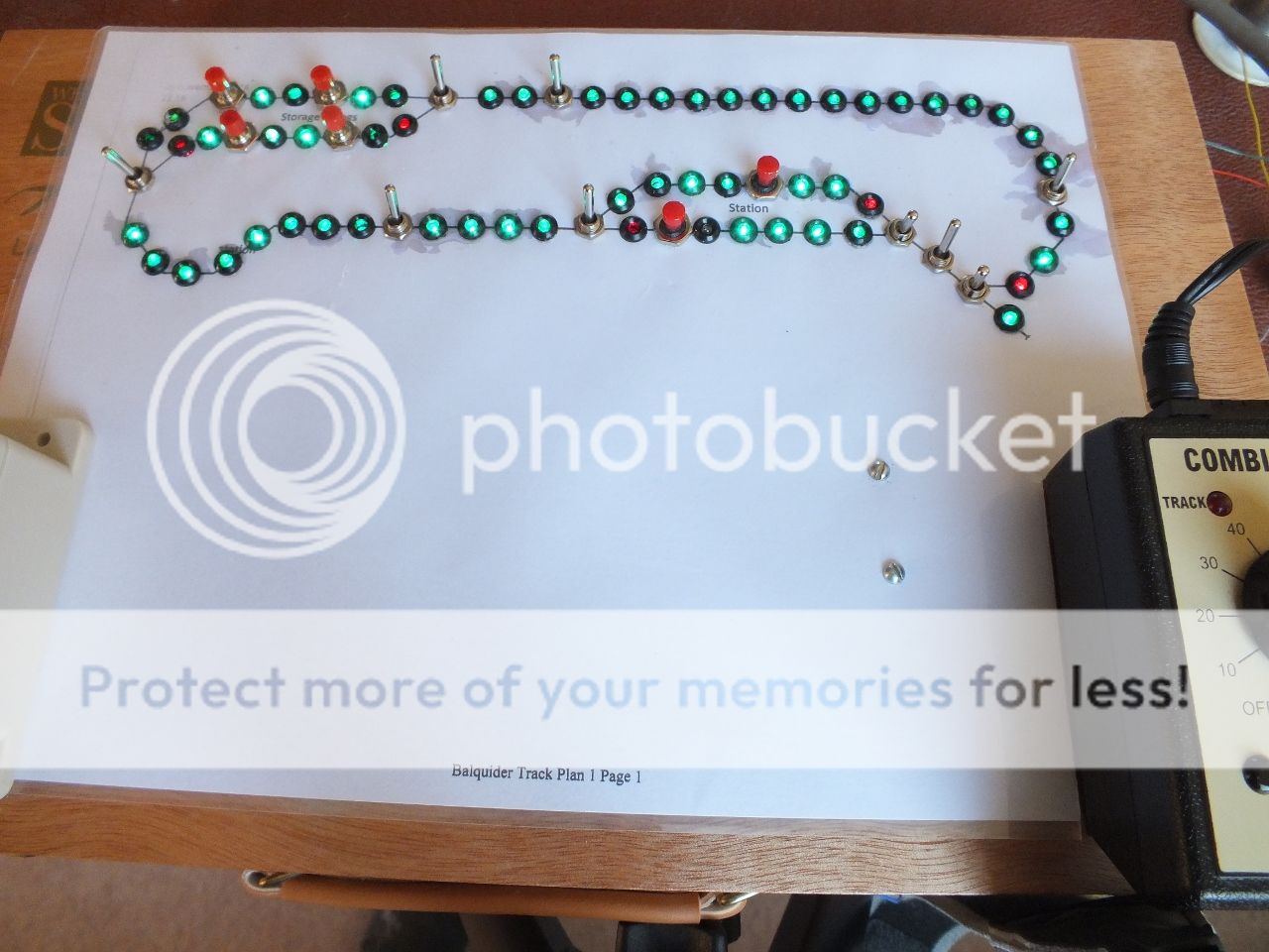
The toggle switches nearest the junction positions, switch the points, and change from red to green to indicate the set route as the next two pictures demonstrate.
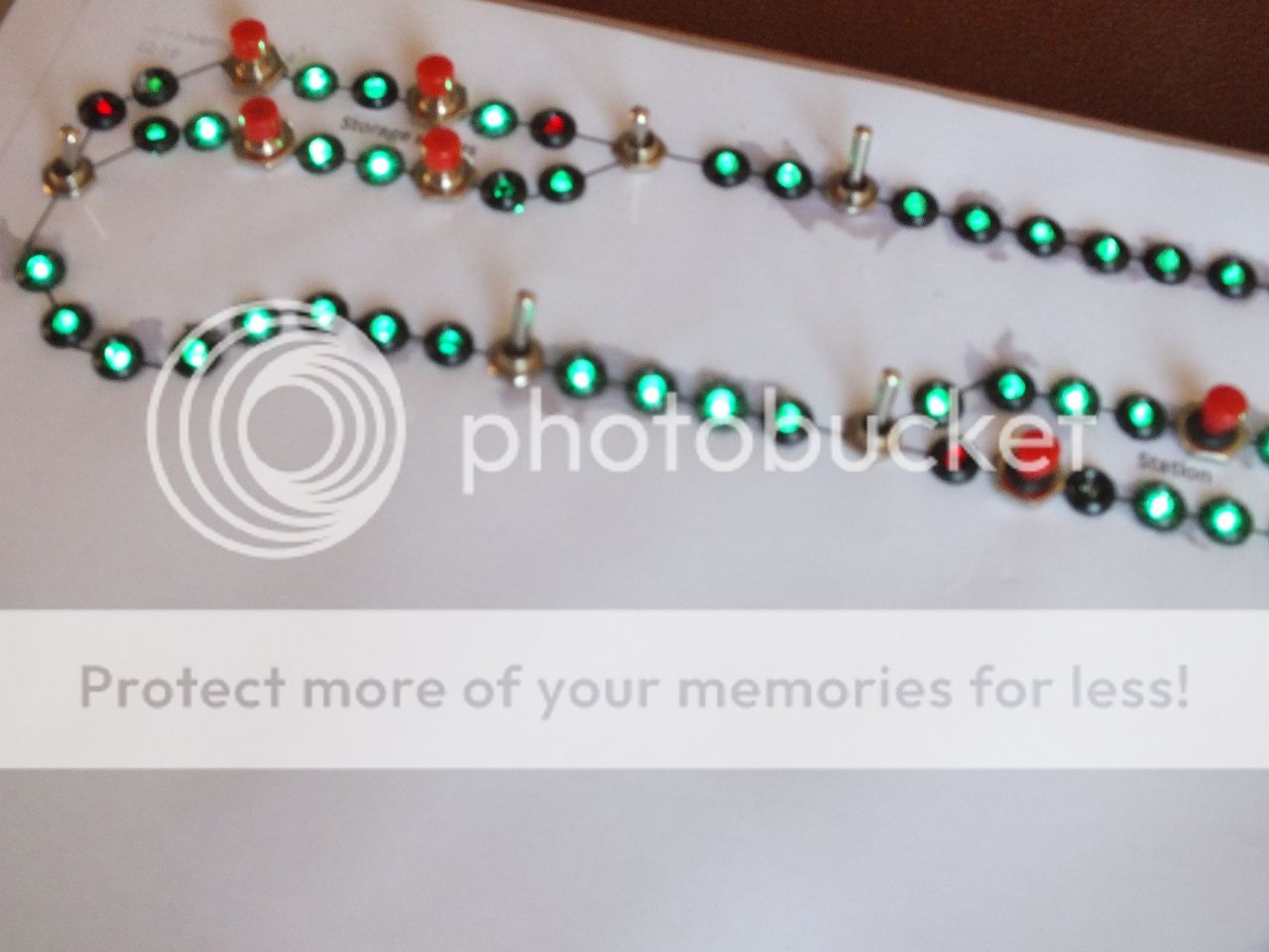
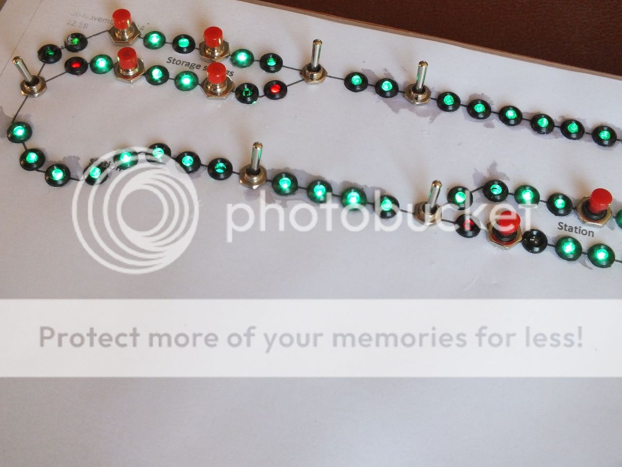
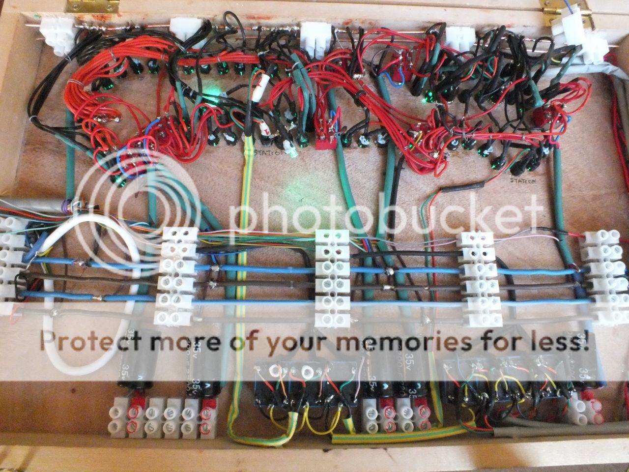
Turning to the inside view, this shows the addition of five 12v single pole changeover relays, (12v SPCO relay), these are used to change the dual colour LED's that indicate a loco's occupancy of the short stop sections in storage sidings and stations from green to red. The relays are switched by in track reed switches operated by loco mounted Neodium magnets.
A closer look at the relays shows the wiring, and to aid identity of the LED colours, the CO contact terminals are wired in the appropriate colours, red and green, this helps for future fault finding if required.
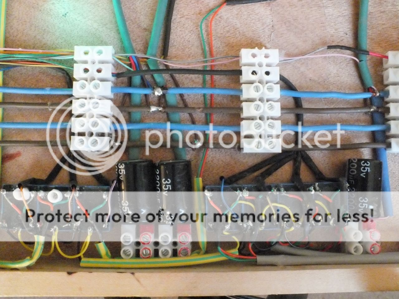
I could have used Changeover track mounted reed switches to achieve the same results but this would have required an additional wire , from each of the five reed switches, back to the control panel, and I've only got twenty seven to play with :o To test the circuitry, I assembled this test rig and connected the appropriate cores form the 25 way cable that will ultimately connect the control panel to the base board,
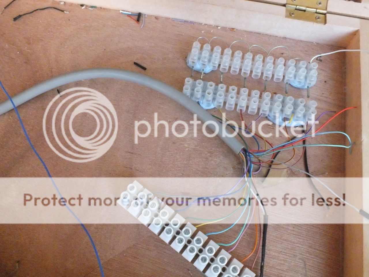
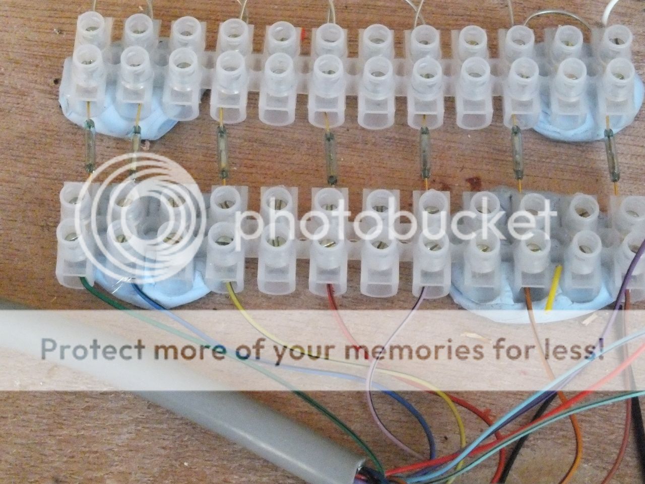
All the circuits tested out.
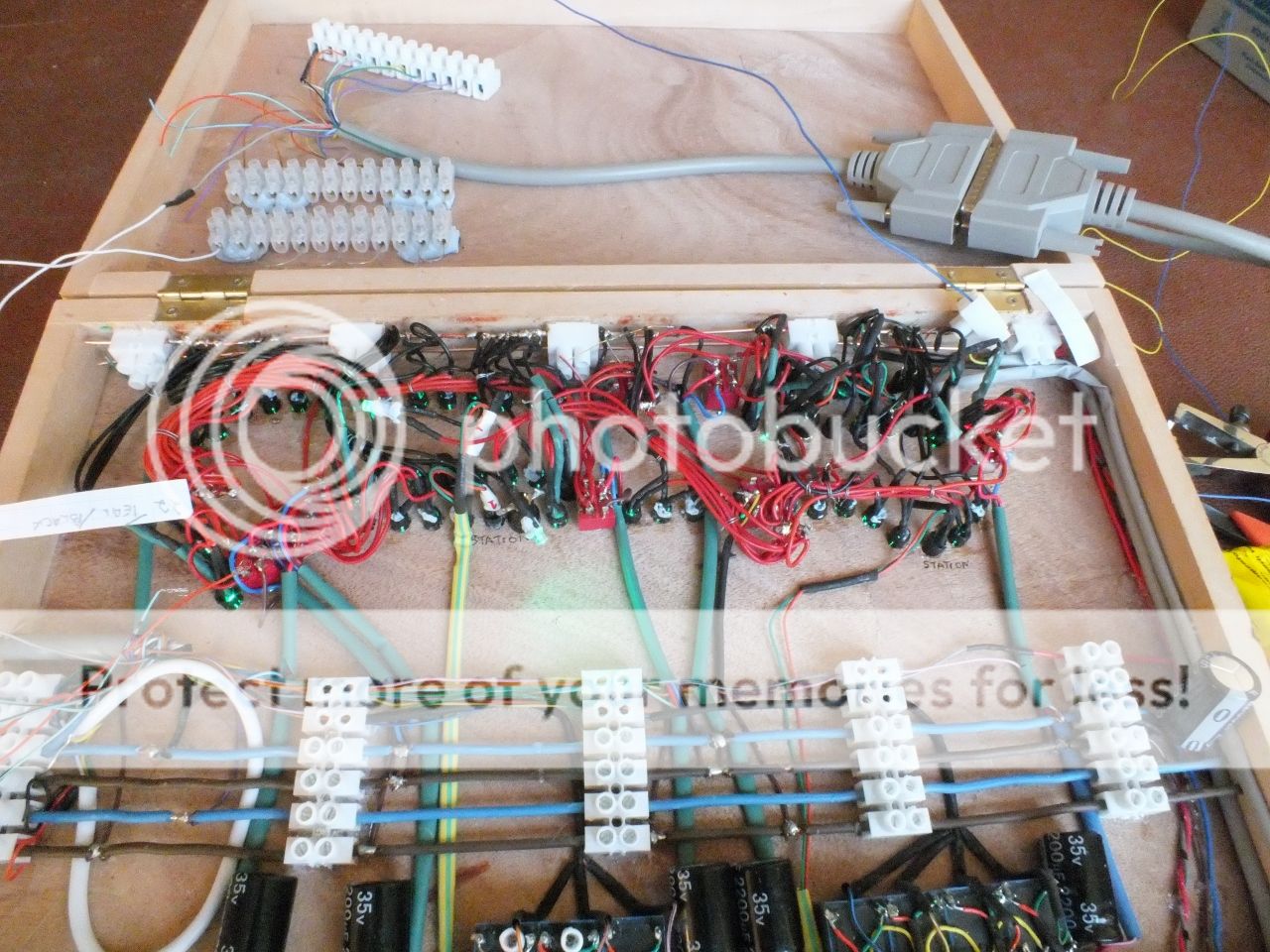
All the point circuits operate a connected point, all the point switches show the selected route, and all the reed relays operate the correct coloured LED. All I have to do now, is wire up the stop section release switches, and that will complete the control panel.
More wiring later.
Regards,
BrianT.
1 guest and 0 members have just viewed this.

