BURROWBY UNDERHILL, a resurected Rabbit warren layout in 009
Posted
#244302
(In Topic #13494)
Full Member
I was just been browsing the various forums, as you do when you've nowt better to do,
 and I was looking at the exhibition calendar on the 009 website and got a real shock:roll:.
Some where in the back of my mind I thought that the imminent East Midlands Groups exhibition was jangling warning bells. I normally visit this exhibition because it is reasonably near where I live, and Roger Budd the co-organiser, visits our 009 Yorkshire group meetings near Doncaster occasionally, usually looking for willing modellers prepared to travel to Mansfield with there layout, my last visit was to exhibit Knottworthy, although of course this is an 0/16.5, 7mm narrow gauge layout.
Any way, I must have promised Roger that I would bring my 009 Rabbit layout to the show, now as some of you might know, I have been engrossed in the Knottworthy alterations since its visit to the Pudsey show with a friend from the 009 group who came along to help me on the day, he jokingly pointed out several disparities in the running of the Knottworthy layout, ie. it had very little operator interest really, hence my acceptance of his criticism prompting the ongoing alterations now underway to the Knottworthy layout.
Some years back, I once promised Roger that I would take a layout to the Mansfield show, this would have been with Glen Ogle. I had to cry off because of one of my many visits to hospital for something or other, and I while convalescing, I subsequently gave the layout away, thinking I would never be in a position to venture onto the exhibition circuit in the near future, so no one ever did see it in the flesh so to speak. When I read that Brian Twigg was going to show his UNAMED 009 layout in the pre show blurb on the 009 events page, I was in a real panic.:shock:
The layout has languished in my garage for the last four or five years as I worked on Glen Ogle and then Knottworthy, and as such, has suffered from building damage, which I knew about, but I thought I had only to connect the electrics back up so it ran, then sort out the building's and scenery to be able to take it to Mansfield's Portland College
The layout in its present state, most of the scenery buildings have sufferd damage, these have been removed for some TLC except thankfully, not the two station buildings.
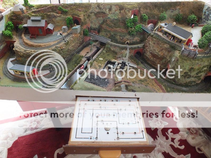
The Rabbit layout was built to please my at the time, very young Grandson, and over a period of time, had many additions to the simple concept of a train bobbing in and out of tunnels as it perambulated around.
I added many little electrical gimmicks to keep him amused, as you do, if you can, so powering it back up, especially as I have not operated it for a considerable period of time, I suppose was never going to be as simple as I thought.
So I ambled into my garage to do the electrical work in powering it up, and oh boy, did I get a shock:

The rear view of the layout showing some of the controls fixed to the back scene.
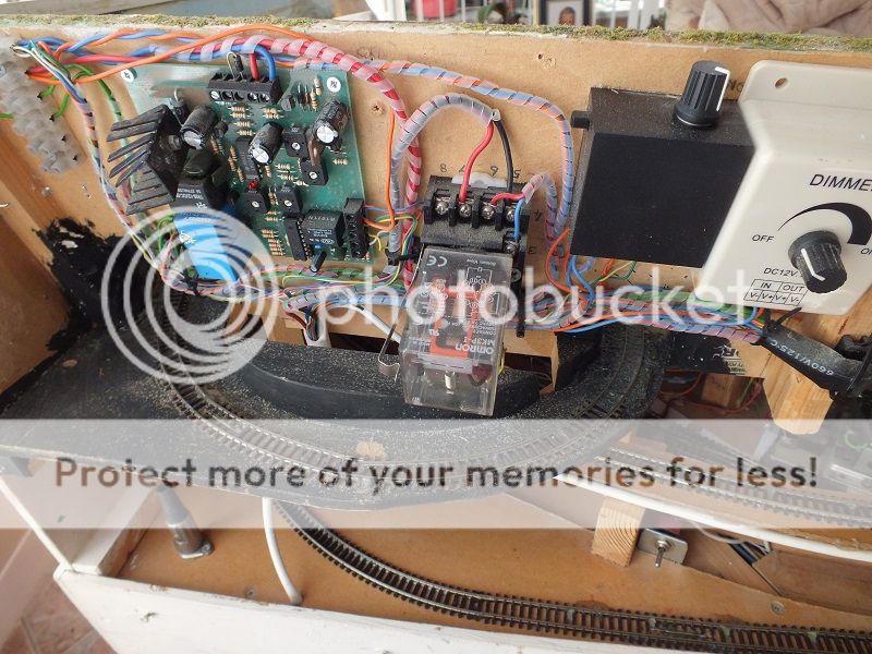
Unlike my present work, the rabbit layout is all analogue controlled, with electric points, a working wind mill. working lock gates on the canal, automatic train stop and start from a hidden siding, as one came off scene it released a stored one to replace it, there is also a double auto train stop start timer from off scene into the station, which when activated, changed the points from the two hidden sidings onto the main circuit and then off the main circuit and into the station bay platform, plus several automatic colour light signals scattered about.

A view of the whole of the rear of the layout.
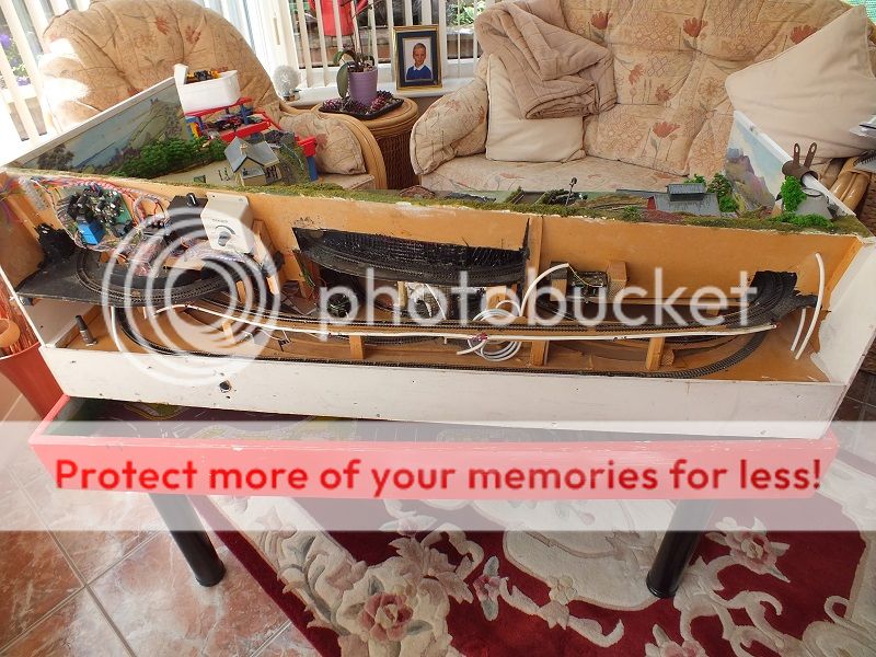
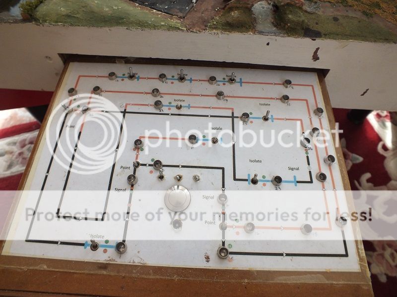
The control panel is a pull out slide drawer on the front of the layout with lots of LED's, outlining the track diagram, point switches, section switches and gismo control switches, all connected with multicore cables to allow the drawer to slide in and out of its hidey hole.
The control panel of the layout which slides into a drawer out of the way.
The electric for all this was fed to the base board via an eight way Din plug and socket, from a home made power source with triple transformers, rectifiers and CDU capacitors, for the various voltages, AC or DC as required at various voltages.
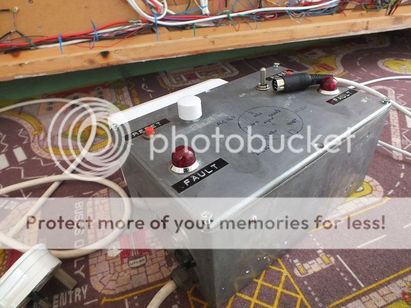
This power source has been altered, probably for Glen Ogle in its early build days, when that too was going to be analogue, and is no longer exactly as required for the rabbit layout, and I am puzzled why I used an eight way DIN plug, as potentially, only six wires would have been required from the triple power source enclosure.
So I have to check the wiring to find out what does what, and as usual, most of the wiring is under the base board except for the relays, timing module and some other bits which are accessible as they are mounted on the layouts back scene board, the base board is only 4' x 2' (1220 x 600mm) so is not particularly heavy, I had a quick peak underneath to see what's what, shuddered and lowered it quickly back onto its trestle stand
 .
. This was why I shuddered, the underside of the base board.
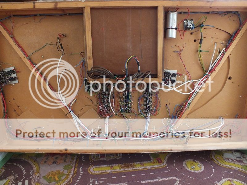
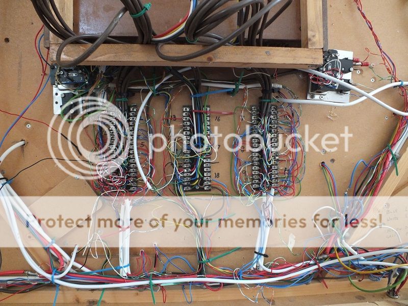
There is a lot of work involved in wire tracing and power supply modifications required before the first train is able to run on the layout, and that is without all the scenery repairs to do.

 WHOOPEE, I've got four weeks to the show, so any help would be appreciated.
Onward and upwards as they say.
Regards
BrianT
 Last edit: by gtmspyder
Posted
Site staff

That lot will keep you busy and out of mischief for a while
Popcorn at the ready, watching with interest
Cheers
Matt
Wasnie me, a big boy did it and ran away
"Why did you volunteer ? I didn't Sir, the other three stepped backwards"
"Why did you volunteer ? I didn't Sir, the other three stepped backwards"
Posted
Full Member
Surely you just consult the original wiring diagram……………………
Shed dweller, Softie Southerner and Meglomaniac
Posted
Site staff

Wasnie me, a big boy did it and ran away
"Why did you volunteer ? I didn't Sir, the other three stepped backwards"
"Why did you volunteer ? I didn't Sir, the other three stepped backwards"
Posted
Full Member
Ahh, definitely some "well I never" moments. DCC conversion would probably be faster.
From the depths of the armchair: essential (track power, locomotive control, points), nice to have (lights, auto reversing, bells, etc.), never in a month of Sundays (well, 4 to be exact). Trying to fix the wiring to what it was versus having a C.F. Rabbit Warren that demonstrates the point of the excercise.
Why not do a work in progress? That way you can work on it, get the basics working, and talk about it at the show. How about "the DeeCee to DeeCeeCee Junction"?
Nigel
©Nigel C. Phillips
Posted
Full Member
What I need is a modeller who can sort the electrics and repair the damaged scenic buildings, living near enough to offer more practical than spiritual help:doublethumb, that must be me then:pathead:cheers.
There's nowt like a colourful post to cheer one up in a morning is there, and this is nowt like a colourful post, but its the best I can do.
Kind regards to ALL my readers,
BrianT.
Posted
Site staff

Cheers
Matt
Wasnie me, a big boy did it and ran away
"Why did you volunteer ? I didn't Sir, the other three stepped backwards"
"Why did you volunteer ? I didn't Sir, the other three stepped backwards"
Posted
Full Member
One of the downsides of living in Virginia, the daily commute means sitting in the bus for 5-6 hours each way. And costs about $5000 a week. And that's cattle class. (My record is 3 returns in 8 days, 2 for work, one 'cos I need the points to keep my Air Canada frequent flyer elite status, back then worth it's weight in gold).
I am not sure you would want me rummaging around the electrickery, unless it is DCC. I shall continue to support your efforts from the armchair. Not coming over until the fall, otherwise I would have offered some actual help as opposed to totally unhelpful commentary.
As I said, break it down into necessary, then nice to have, and finally not necessary for the show.
Nigel
©Nigel C. Phillips
Posted
Full Member
Regards,
BrianT.
Posted
Full Member
I have had to admit I have been defeated by my own technology, I just couldn't remember what all the wiring did to be able to modify it, I was spending too much time trying to trace the wires, so snip snip time wholesale, and I am now re-wiring, but in a very basic way, no LED's, No wind mill , no waterwheel, no timed shuttle train into the bay platform, and as yet, no delivery of the new CDU to be able to operate the dammed points.
So, just an ability to circulate trains and switch the points, hope fully.
Regards and dejected in defeat,
BrianT
Posted
Full Member
For instance, one of the problems was that the points would not operate, the capacitor discharge unit appears to have packed up, and because of time constraints, I ordered a new one off EBAY. It arrived last Saturday the 8th, three days after it was supposed to, and I was out at postal delivery time. Now normally our postman, if he cannot get an item through my letterbox, will hide it somewhere and leave me a note, but, Sods law, the regular postie was not on, and his replacement pushed the none delivery note through my post box, but bent it and it did not come right through, and I did not spot it until Monday, 10th. But instead of being the usual red one, this one was white, and told me that it could not be delivered as the wrong postal charge had been applied, and I owed them £1.50, so grumble grumble, I went to day to collect it, payed my £1.50 and came home.
The parcel would easily pass through my normal sized letter box, and I am about to take up this matter of additional postage costs, with the manufacturer.
The unit is very well made with good quality components, and has an output of 18600 Mf, more than sufficient to slam my H&M point motors from one side to the other, but it is not working correctly.
This is just one of the series of events that have thwarted my attempts to full fill my obligations to the show organiser.
I should point out if you have seen the mass of wiring that originally worked every thing, that I have completely stripped every thing away and added NEW point wiring,and NEW track wiring, and dumped all the gizmos that I had added to amuse my Grandson.
But without the points working its a none goer and I'm fed up with the damn thing.
I'm going for a laydown now, catch up later.
BrianT.
Posted
Full Member
This has resulted in me ripping out the plethora of wiring that originally successfully made it work, so to visually re-cap, here are some pictures of the layout and its attendant wiring, before my frustrated attack with my side cutters, and after.
A view of the layout, as brought out of my garage, where it had been used as a shelf for the past eleven years, with several of the partially damaged buildings removed in readiness of some TLC. The working windmill, the working water wheel mill, the working lock gates, and the working colour light signals. The track plan on a pull out drawer had all the point toggle switches with there large chrome industrial master push button firing switch, each point had a red/green LED showing the direction of travel, and the rest of the LED's showed sections which could be switched on or off with red/green LED's, and the travel of the train was indicated on the plan by green LED's operated by in track reed switches as the train perambulated around the track. Out of site was a long stretch of track that ran along the rear length of the layout, divided into three isolated sections to hold three separate trains, as one train came out, the other two followed up into the released, sections making room for a circulating train to pull into the newly released section to the rear. This was indicated on the track diagram by three push to make switches and three red/green diodes.

A closer look at the pull out control panel.

The single spur in the centre of the control panel, eventually became a double spur out of site under the scenery to hold two further trains off scene. This was controlled by an electronic timing unit that selected a train, set the point for it and brought it out, changing a point to bring it onto the main circulating line for a short way ,and changing another point to direct it into a bay platform at the lower station, this is not being shown on the track diagram as it was probably the last of many additions I made to the layout to amuse my Grandson. While all this was going on a further train would be circulating the layout completely unaffected, would pass through the lower station, and when it had cleared the section, a timer would kick in and reverse the whole procedure to park this loco off scene, and reset the track for the circulating loco for when it returns.
The timer and relay that did all the above jiggery-pokery, picture below.

The three train storage track running along the rear lower deck of the layout.

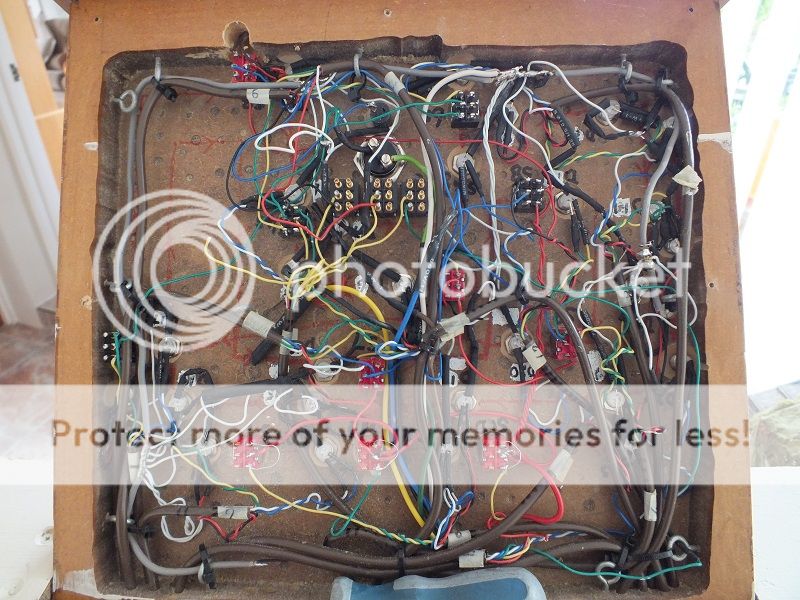
The underside of the layout showing the original wiring, before its wholesale removal as I was getting nowhere fast.

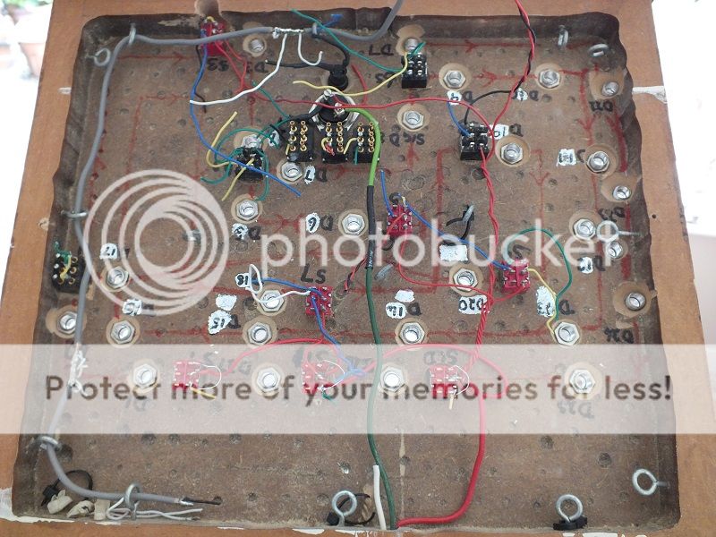
And this is the wiring after the snip snip exercise.
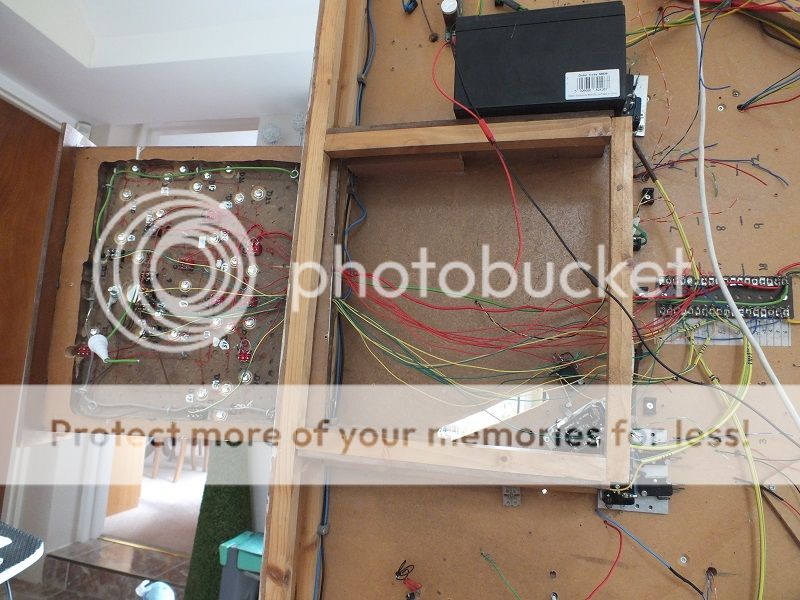
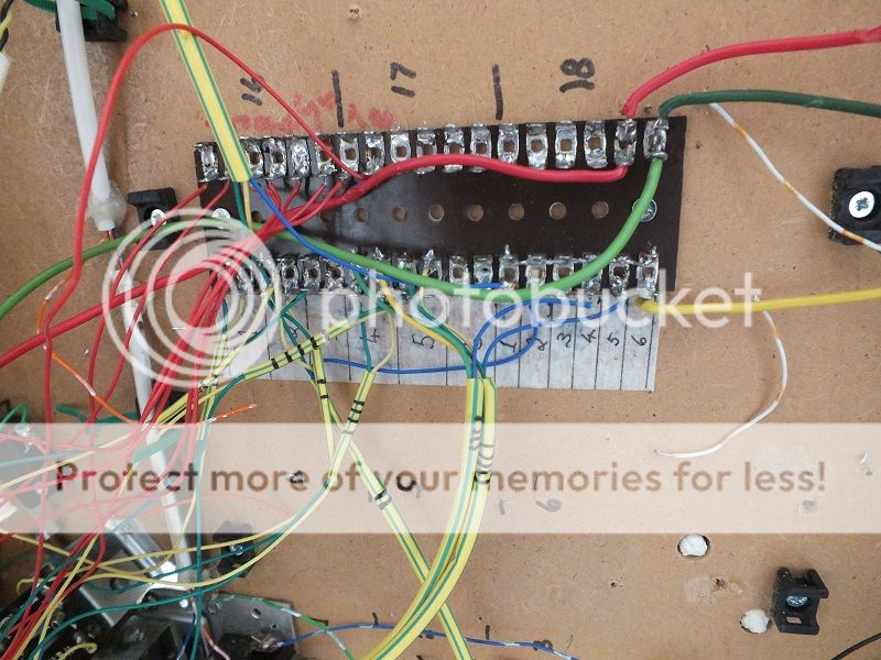
The new wiring replacing the original the green and white sleeving carries the new point wiring of green, yellow and blue common, the red wires are the new wiring to connect the control panel section switches to the track sections.
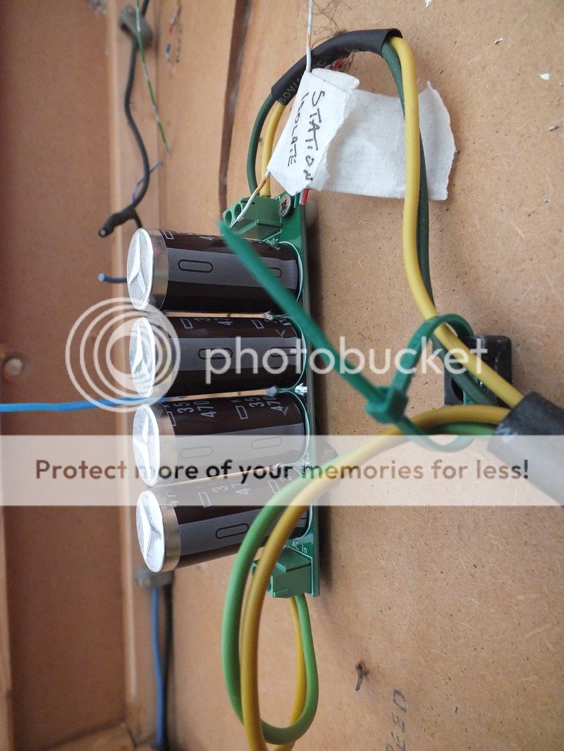
The new CDU that I purchased to replace the old original one, the new unit does not work when I connected it into the wiring.
The inside of the underside of the track diagram before the snip snip moment.
The underside of the track diagram after the wholesale clear out of surplus wiring.
There have been several setbacks during this attempt to resurrect the layout, and I have really struggled, but the final straw for me, was the purchase of a new CDU, that when connected, does not work the points, and I have given up the struggle and called it a day with Burrowby Underhill.
I will be at the east Midlands show at the Portland College, Mansfield, thanks to the kind offer from a fellow 009 member, Mr John Andrews, who has offered me the loan of one of his layouts, and who I hope will accompany me to Mansfield to receive due credit for what is a very nice little layout, which will give pleasure to the viewers, and enable me to honour my commitment to Roger Bugg, by filling the gap allocated to Burrowby Underhill on the day.
Kind regards to all the people who have offered support and encouragement over the last few days, but enough is enough.
BrianT.
Posted
Site staff

Ron
NCE DCC ; 00 scale UK outline.
NCE DCC ; 00 scale UK outline.
Posted
Full Member
John calls this little layout a decorated test track, but when he demonstrated it to me, I was very pleased to find that it is a very nicely done test track, that only required a quick wash and brush up, to be up and running, so I gratefully accepted his kind offer and brought it home with me, and for the last few days, I have been beavering away getting it into an exhibtion'able state.
The layout has now been ballasted, the points have the switch blades of the dead frog points now polarity wired back to seven DPC over slide switches, grouped and mounted on a plate of Opel Perspex, with the operating slide dollies drilled to accept a piano wire operating rod, running in Nylon tubing, when the supplier gets his/her finger out and finally delivers the tubing.:sad:
The Gaugemaster controller feed wires have been altered slightly to accept a double pole Mono plug and socket for ease of setting up.
The holes to accept the Nylon tubing have been drilled ready for the tubing runs, to take them below the baseboard. This was done using a 300 x 4mm home made drill to be able to drill through the existing baseboard and scenery at a very slight angle to keep the tubing as flat as possible between switch and point tie bar, only time will tell whether I have been successful in this work.
The scenery has been refreshed with new scatter materials.
Several of my analogue 009 loco's and rolling stock have been test run around the layout, and the local population has had an increase in numbers.
All I have to do now is await the arrival of the Nylon tubing, fit it and hope that the test operation of the switch/point changeover dollies operate the points as intended, no pressure there then?:Happy
Regards,
BrianT.
Posted
Full Member
Hope the show goes well and that we see the Rabbit layout back to its former running glory.
Michael
 Last edit: by Headmaster
Posted
Full Member
I have now got this loan layout, and I have been working on that, I've got all the loco's I'm taking with me working, I've freshened up the scenery, and a few other little bits of alterations sorted out, just got the point operation to sort now, I've done as much pre preparation as I can, just waiting for the Nylon tubing to arrive.
I'll take a photo when and if the tubing arrives.
Kind regards,
BrianT.
Posted
Full Member
I had bought the Nylon tubing from Ebay, from a pneumatic supplier, a lot cheaper than the Mercontrol supplier for point operation.
Having seen the Urology consultant, I was not particularly bothered about getting back to railway modelling, it was not good news.
Any way, I have now got back into the swing of things. the 1/8th Nylon tubing was ok for the purpose. and I'm now busy trying to fit the tubing and piano wire in place to operate the points, and it is not as easy as running a few wires and point motors!!!
Relatively easy on a dead straight run between switch and point, but on a finished layout, and with a centralised point operating position, as you would or could with electrics, not so easy at all.
Anyone who uses this method to switch points on their layouts, will have by now realised that I have never used wire and tubing unti now, but I am getting there, sslllooowwwwlllly.:oops:
Regards.
BrianT.
Posted
Full Member
The layout is a simple roundy roundy, with a passing loops to the front and rear, an engine shed road off to the front left, and a goods storage road off to the right.
So, simple to operate, with ample room to hold at least three made up trains.
John gave me permission to do more or less what I liked with it, as he had built it more as a test track than a layout.
The scenery he had installed was a little tired, and the track had never been ballasted, the dead frog points were all digitally operated, ie you pushed them with whichever digit was nearest to the tie bar.
This worked perfectly well when John dragged it down from his loft to demonstrate it to me, and he was happy to let me bring it home with me.
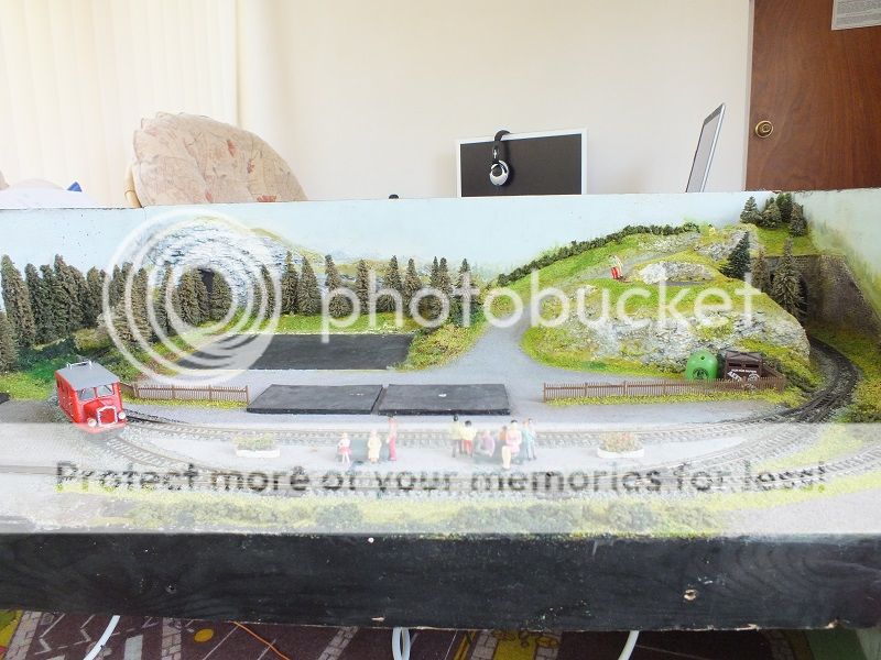
The little layout after I had freshened up the scenery and ballasted it.
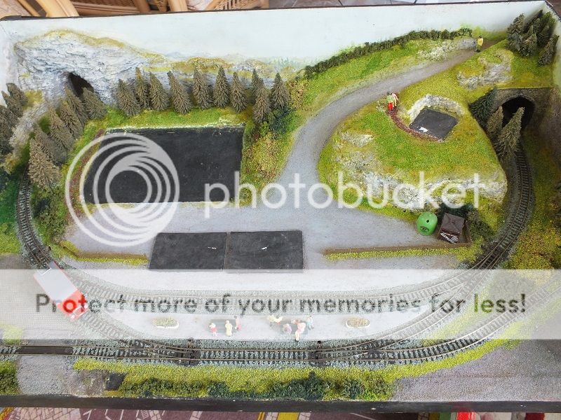
The black base patches are where John's scenic buildings sit, which are still packed away in my garage just as John
packed them for me to take away.
My wife bless her, was not so happy, as my garage now housed three railways, and sundry quite large wooden toys I had made my grandson ,over his thirteen years of existence.
One bright red half size all electric Land Rover, a 20 note Barrel Organ built in a stage proscenium arch setting, a Ukulele, three Violins and a Viola for my children when they were in the Rotherham Youth Orchestra during their later school years, and sundry small wooden models of various things.
The three layouts were my 7mm 0.16.5 narrow gauge Knottworthy Magna layout, the 009 Burrowby Underhill, rabbit layout I had made for my three or four year old grandson at the time, and which gave me so much trouble trying to resurrect it after seven or eight years lying unused in my garage, and John's 009 continental swimming pool spa, who's name I have already forgotten.
In mitigation, I have just been diagnosed with Prostate Cancer, and Thursday, the 27th of June was our 60th Wedding Anniversary, so she was treating me gently, and I think I've got away without too much aggro.
My postings have shown the problems I have had with the Burrowby layout, mainly due to my ever poorer memory, and my complicated wiring, so with a new layout to play with from John, I set about doing a little refurbishment.
The scenery and ballasting were soon done, and I wondered what else I could do to make the layout less vulnerable to glitches and fingerpokening.
I was wary of the dead frog points, which relied on the side contact of the switch blades to make electrical contact, so I wired the crossings similar to live frog points.
This required each point to have a selector switch to alter the polarity of the point crossing, and so I thought I would use wire in tube to move the point blades and switch the crossing polarity, a method that I hade never used before.
Because I am used to wiring things up, I made a bank of seven DPCO slide switches into a control panel mounted centrally at the rear of the layout, I had to make a 300mm x 4mm drill to be able to drill for the Nylon tubing below the existing scenery and baseboard at an angle, it all seemed simple enough at the time.
When I fitted the Nylon tubing and enclosed piano wire in place, bent the ends of the piano wire and attached it to each tie bar and appropriate labelled switch, and found out that really, this was not the way to use wire in tube operation.
I had clipped all the tubes in nice gentle loops where I could not get a straight run using Burglar alarm wiring staples, from my time of helping friends, by installing burglar alarms for them. and it all looked very neat and shipshape. All the switch wiring was run to the frog positions using multicore alarm cable back to the DPCO switches, BUT, it did not work.
Not because the tube & wire was too stiff due to the bends, but because there was insufficient movement in the slide switch dollies, to take up the slack in the operating tubes.
The underside of the layout showing all the wire in tube runs, and the frog to switch cabling. The switch panel is over the central baseboard support, all the cables and the wire tubes are clipped to the baseboard with Burglar Alarm cable staples.
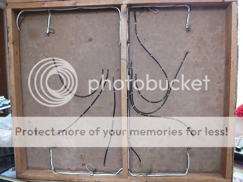
Some of the point blades were moving, but not all, and I could think of no way to remove the inbuilt slack in the curved push/pull operating links.
So I removed all the curved sections and just used the straight push pull sections, cut my switch mounting up, to just leave the four straight operators, but even then, the inbuilt slack made the operation unreliable, so all this was removed, and I decided to return to the digital operation of the seven point switch blades.
The mark 1 wire in tube switch block I made , cut from a seven switch operator down to a four block when I tried going back to a straight push pull operator wire configuration. And when that did not work, the MK3 switch mounting block with the DPCO slide switches changed to DPCO toggle switches, geographically placed on a track diagram.
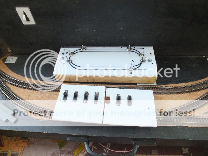
But when I tried the layout running with fingerpoken point operation, the loco's were stopping mid point in some cases, I then realised that because I had altered the frog operation, the frogs needed to have a switched feed for the polarity.
This entailed making a second switch mounting frame, with a track diagram and the DPCO toggle switches mounted in the appropriate position on the track diagram, so I rewired the points with six core alarm cable, with the intention of putting point motors in place, but by this time, my enthusiasm was on the wain, I was constantly tired because of the new medication I had been prescribed, my limbs seemed not to want to cooperate, and I have given up on the point motors.
The under side of the layout with the latest wiring installed, with intention of fitting point motors at each point position, the seven 6 core cables will carry all the wiring from the switch panel position to each point motor, when all was finished, the points would be fed by a capacitor discharge supply using a single firing button when all the point switches had been set for the route.
The single cables dangling are wires from the earlier wiring to the frog live side, all the blacks are wired as common return. The older live side wiring will be replaced by one of the cores in all the new 6 core cable runs back to the new switches, and fed from the live side feed wire from the controller. The six core cable ends have just been left dangling until the new point motors were fitted, then they would have been connected to the appropriate point on the seep point motors and finally clipped to the baseboard. You will be able to see the grooves cut into the baseboard where the first wire in tube runs terminated at rgw point tie bar positions.
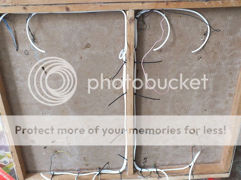
So the point operation will be fingerpoken, I will finish wiring the frogs to the switch positions with the already run cabling probably tomorrow, and hope that all will be well.at the next testing session.
We will just have to remember after the fingerpoken movement of the point switch blades, to switch the toggle switch to the correct position to change the polarity of the frog as appropriate.
Kind Regards from a very tired and chaste modeller,
BriantT
 Last edit: by gtmspyder
1 guest and 0 members have just viewed this.

