Building an MSE signal kit.
Posted
#264962
(In Topic #14427)

Full Member
It's not something I need tomorrow so I'll build it slowly doing a little here and there whenever the urge grabs me.
I like the N.E. lattice post signals and assumed, if I could build this, I could build most of the other non-gantry types ……………..

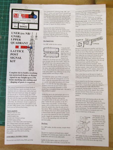
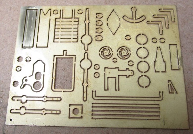
This is what's in the packet - some very tiny bits !!! :shock:

I like the comment "some marking out, cutting and shaping required" …………………. that's the understatement of the month !
'Petermac

Posted

Full Member
Cheers,
Claus
www.flickr.com/photos/ellef/
Claus
www.flickr.com/photos/ellef/
Posted

Full Member
I've got one of these waiting to be built. Looking forward to your instructions

Barry
Shed dweller, Softie Southerner and Meglomaniac
Posted

Full Member
Nice one!I've been wanting to have a go at one of these for some time.
I like the comment "some marking out, cutting and shaping required" …………………. that's the understatement of the month !
To quote Wikipedia; "As they survive, the labours of Heracles are not recounted in any single place, but must be reassembled from many sources"
I think you just found the long lost labour #13
Colin
 Last edit: by Colin W
Posted
Full Member
I did make a start yesterday but was interrupted when someone "popped in" to say hello - and stayed for 4 hours !!! Lots of expensive air-con went to waste to boot ……………….
Anyway, as with most things, there are instructions to read - fairly comprehensive ones - if you already understand signal terminology …………

Then - a proper start with the bits …….and mein Gott, there are some extremely small bits to work on.
Not altogether sure I'm going to enjoy this build when an instruction suggests drilling out a hole for the operating wire "starting with a 0.8mm drill and working up from there". The part to be drilled isn't even 0.8mm wide and the operating wire in question is only 0.31mm diameter so, following the instructions, I'd get 2.5 wires into the hole but the hole would be bigger than the etch I'm supposed to be drilling……………… I feel a note to Wizard Models coming on ………..
'Petermac
Posted

Full Member
Nigel
Last edit: by BCDR
©Nigel C. Phillips
Posted

Full Member

Good luck Peter - you may need a ladder

Posted
Full Member
Hi Peter,..
Not altogether sure I'm going to enjoy this build when an instruction suggests drilling out a hole for the operating wire "starting with a 0.8mm drill and working up from there". The part to be drilled isn't even 0.8mm wide and the operating wire in question is only 0.31mm diameter so, following the instructions, I'd get 2.5 wires into the hole but the hole would be bigger than the etch I'm supposed to be drilling……………… I feel a note to Wizard Models coming on ………..
When looking at MSE signals as one option for Upper Hembury, I evaluated their GWR Square post signal. Like yours, the GWR fret has 8 or so tiny washers so I'm guessing this is what you're referring to as well. In the GWR instructions which I downloaded it says"
"Solder one of the etched washers to the end of a 26swg nickel silver axle, having first opened out the washer hole to 0.50mm (no.76) and before removing the washer from the fret. Pass the axle through the holes in (7), trapping the balance lever so that with the open jaw upwards, the crank is pointing down through the slot, and the weight is to the right."
I've a feeling this is a more suitable line of attack, hope it may be of help.
Colin
Last edit: by Colin W
Posted

Full Member
. . . . . . . . . . . . . . . . . . . . . . . . . . . . . . . . . . . . . . . . .
(fill in the blank space to suit personal circumstances and continue on a blank sheet of paper if you need more room).
Bon courage as we say round these parts. Me, I'm just a lawnmower / will continue to use Dapol*, you can see by the way I walk!
*delete as appropriate
Bill
:cheers
At 6'4'', Bill is a tall chap, then again, when horizontal he is rather long and people often used to trip over him! . . . and so a nickname was born :)
Posted
Full Member
Not too sure I have a nickel silver axle Colin although I haven't got as far as the balance arm yet - still trying to get my head around how one makes a neat job of soldering brass photo etch …………………..
Is my iron too hot, too cold, too big, too small, wrong solder, wrong flux, wrong operator ………………???? The quest for a decent joint (as seen on You Tube), continues………
As I also aim to make some photo etch coach bogies (already purchased), I thought I should at least make an attempt to obtain some useful gadgets for the venture so purchased one of these:
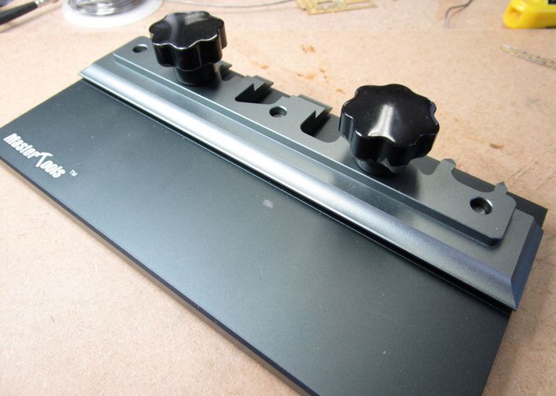
I have no idea who makes them but this model is marketed under the Trumpeter label. Thus far, having used it for just two bends, it's proving to be a great bit of kit. :roll: This side for long bends (read lattice post signals), flip the clamp part round and the other face is for odd shaped small bends (read, hopefully, coach bogies…)
At this point, I am forced to admit what soldering skills I'd acquired on track laying seem to have deserted me and are leaving much to be desired - at least on etched brass. Here are a couple of shots of my attempts:
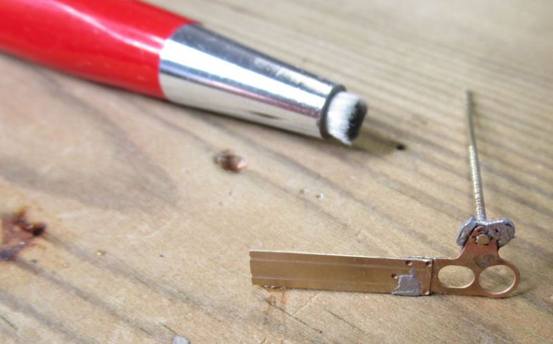
The glass fibre pencil shows just how small these bits are and the grey blobby bits show just how bad my soldering is. I cleaned the brass with the pencil, painted it with liquid flux and tinned it with 60/40 solder - obviously rather more "tinning" than a thin coat !!! Put the parts together and apply heat until the solder flows - or the bit you soldered last, drops off !!!
A 0.95 mm hole was drilled in a block of wood to take the shaft and the signal arm "dropped" (
) over it to ensure a right angled joint then soldered. It neither dropped over the shaft nor soldered to it !! 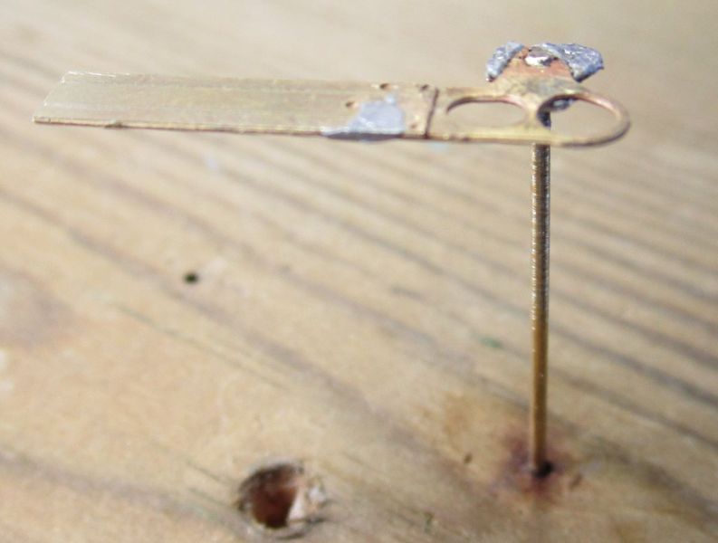
Here, I've attached the shaft to the signal arm - both brass but would the solder take on the shaft - absolutely no chance !!!! It took me forever, took the skin off two of my fingers and I had to re-solder the arm to the spectacle plate part at least twice …………………. Oh yes, I also managed to completely remove the little arm for the operating wire whilst attempting to drill the hole for it. I did try to solder one of the "etched washers" Colin mentioned but that ended up looking even worse than what you see here and that was before I attempted to drill the hole …………..
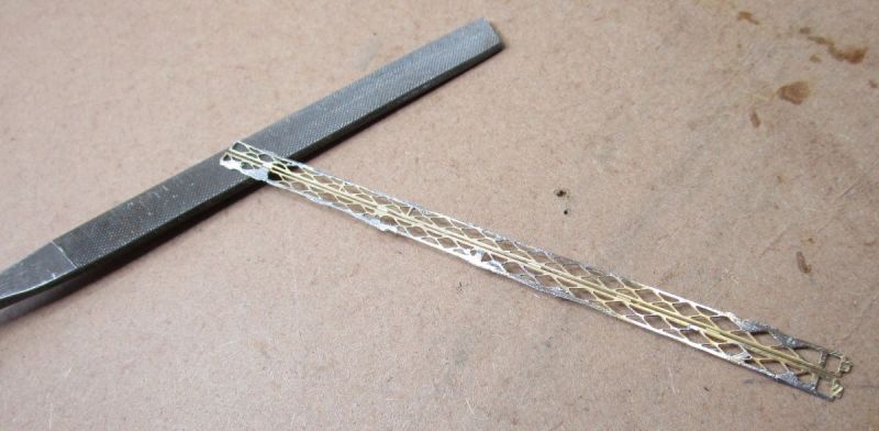
Swiftly moving on to the lattice post ………………….. The instructions say "lightly tin the edges of the lattice posts on both sides of the fret …………" How does one tin "lightly" when there's only a couple of millimeteres between the lattice work and the fret ??? I managed to fill a few of the lattices with my light tinning whilst firmly soldering most of it to the surrounding fret ……… As you might imagine, that made for easy separation from the fret ……….. :twisted: Having finally managed to separate "my bit" from the rest, here's what I had. The file again gives some idea of the scale :
The next operation was to test my new bending machine. As all I had to do was put the etch in and tighten two knobs, I managed it with surprising ease and totally without any personal injury. Once folded to 90 deg. the posts became remarkably sturdy - I can imagine, once I get the two sections soldered into a rectangle, it will be very strong.

Now I need to do some swatting and get some practice in. I can see this kit becoming my guinea pig rather than a feature on the layout ……………………. :hmm
'Petermac
Posted
Full Member
Looking good so far! You are very brave to tackle this under scrutiny - we are all taking notes!!
Barry
Shed dweller, Softie Southerner and Meglomaniac
Posted
Full Member
It looks so easy on You Tube ………………. :roll:
'Petermac
Posted
Full Member
PS it's looking like I made a good call by settling on using the Ratio kits modified by additions / replacements with finery from MSE rather than the whole works!
Colin
Last edit: by Colin W
Posted
Full Member
I've built the Ratio kits in the past and very nice signals they make, however, they are extremely fragile and I never managed to get one to remain in place for more than a couple of reaches over the layout ………
I'm hoping these will be more robust and also, I'll learn how to solder more skillfully …….. :cheers
'Petermac
Posted

Full Member
I have some mental and physical block when it comes to soldering (and bending*) brass kits - I inevitably have to resort to superglue and I have definitely never attempted anything so complex as that signal kit.
I do agree with you about the vulnerability of Ratio Signal Kits to the long reach. I have lost count of the number of times I have had to repair/reposition some of my signals. Happily the Dapol signals I am installing are much more sturdy - I have already inadvertently tested one a couple of times :roll: :oops:
I wish you luck with this project Peter although I doubt if I will be able to offer any useful advice.
* I do like your new bending tool it looks like a very useful piece of kit - probably just what I needed when I attempted a coach build years ago - sadly too late now!
Best wishes
Posted
Full Member
With that in mind, I've already downgraded this kit to a "practice kit" so, once I've gained the necessary skills, I'll attempt another…..or two …….. :roll:
I am already improving on my soldering techniques (I think) having used a bigger, hotter iron and flux in paste form rather than liquid during my "practice" last night.
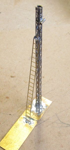
I soldered the 2 halves of the post together, added the large mounting baseplate and the tube to ultimately carry the arm.

The post in rectangular form is remarkably rigid compared with the initial floppy flat etches. The instructions said "now is the time to cut the post to length". Had I read the rest of that sentence, I'd have seen that it said "cut the surplus from the bottom, not the top"………………. :oops: :oops: :oops: :oops: Time will tell if that instruction is critical ……….
In additon, I ought to have used lower-melt solder to fix the post to the large baseplate - using "normal" solder was always going to de-solder the small rectanglular plate on the bottom of the post. Try as I did, I was unable to resolder that tiny plate - 2 of the locating slots had filled with solder as it fell off and all attempts at re-mounting it risked de-soldering the post itself. In any event, it would have gone had I followed the instruction about cutting to length ……….. :???: As a result, I have a fairly untidy lump around the base of the post.
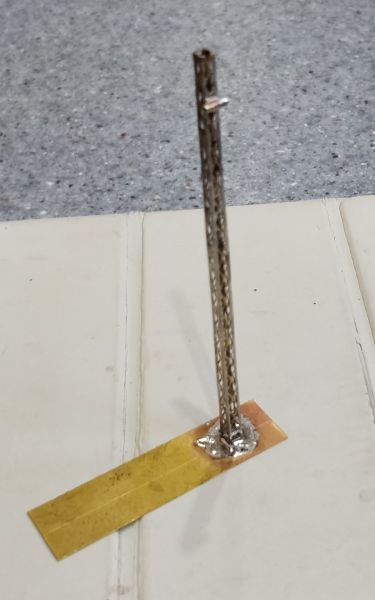
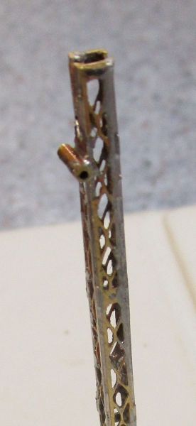
I did use 145deg solder to mount the tube for the signal arm. Not the largest object in the world although these pictures do show it once it's been cut to length with my trusty Dremel after soldering.
Before I continue, I'm awaiting some solder paste which I understand is easier to use than conventional solder on fine detail. I do have difficulty in "fine coating" the solder when tinning - I usually end up with a "blob" somewhere regardless of how little I load onto the iron…….. Paste apparently will prevent this - we'll see.
Another problem I've encountered is actually removing the etches from the fret. Most "experts" seem to use a craft knife of some kind - often with a No 10 type curved blade on a hard surface. It looks very easy and has a satisfying "click" as the brass separates.
I've tried 3 different blade designs - chisel type, straight (No 11) and curved (No 10) and a piece of thick glass as my cutting mat. This "outfit" is excellent at breaking blades but doesn't appear to cut through brass etches.
Maybe my etch is thicker than those on You Tube or my blades too fine. Whatever, it doesn't work very well. I did think I'd buy some special "photo etch cutters" - similar to a pair I have for cutting plastic mouldings from their sprue, but for brass. When I saw the prices, I decided brass etch modellers must be pretty wealthy bods…………… Some, admittedly they looked good, were over €30 !! That's more than I paid for my first motor bike !!! If there are any "etchers" reading this - what do you use to remove the parts from the fret ?
Having initially decided brass etches were not for me when I started, I'm actually warming to them now. Certainly I'm learning new skills which obviously require further practice but it's turning into quite an enjoyable ride. I endeavour to make each joint better than the last. I must also remember to read the whole sentence rather than just the first phrase………………. :roll:
'Petermac
Posted
Full Member
World removed from soldering droppers to rails.
Nigel
©Nigel C. Phillips
Posted
Full Member
The main exceptions are that I don't have any wicking braid - maybe I should get some :roll: - plus, I find that with small irons, whilst they're very handy to get into small spaces, they lose tip heat far too quickly other than for the smallest of jobs. Switching to my more clumpy 80w temperature controlled iron does a far better job at heating the brass.
In my previous post, I said I was awaiting delivery of some solder paste. That duly arrived - or at least I thought it had. Whilst I have absolutely no experience with the stuff other than what I've read, I had no idea what to expect in terms of appearance or performance.
Having tried it several times, I'm almost certain what was advertised as "solder paste" is in fact "flux paste". It does work well as a flux but appears to have absolutely no soldering capabilities whatsoever. It looks very similar to grease although I'd have expected it to have signs of solder powder in there ……………….. I'll need to re-look at the marketplace although I'm not sure what more I can do ……..the tin does say "solder paste" but I'm sure it's not what I wanted.
I've also had more success using Fry's Powerflow flux than relying on the rosin flux in cored solder.
Depending on what and where I'm soldering, I use "normal", 145 deg and 70 deg solders, mainly because those are the ones I have in stock - I think they are all leaded solders ………….. :roll:
One thing I have learned is that I need to wash the work at the end of every session to remove any acid residues from the flux. I do have some "no clean" liquid flux but haven't found that to be as good as the paste fluxes. On one occasion, I left things overnight and next morning there was that tell-tale green staining on the brass. :oops:
I'm still finding it difficult to handle the smaller bits - hands not steady enough and tweezers tend to go "ping" just as the iron approaches. They probably know it's going to be hot…………………
The instructions continue to cause some confusion ………………… :hmm
Not much progress of late - just the ladder and stays added. The instructions said "having removed the top rung, bend it over at about 130 deg above the new top rung" - I have absolutely no idea what they meant by that so didn't bother …………
Fitting the stays proved to be a delicate operation. I put a "swan neck" in the rear stays to compensate for the ladder being somewhat wider than the signal post. The instructions said "joggle the stays" to accomotate the difference ……………… :roll:
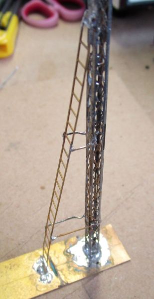
The photo makes it look worse than it actually is plus, when viewed from Bordeaux, one wouldn't notice the problems anyway …………….. :doublethumb
I'll now do some further research on "solder paste" ……………….. :cheers
'Petermac
Posted
Full Member
It seems leaded solder paste isn't available in France - RohS regulations may have something to do with that …….
I could get some from "overseas" - at a price !! good heavens, it's expensive and way more than I'm prepared to pay.
I can get lead-free paste - not many suppliers at anything like a reasonable price but I'm not sure I want to go lead-free. It's much harder to use requiring high heat and, from what I've heard, doesn't "flow" as well as leaded stuff does.
Can anyone shed any light on why it's so expensive other than the fact that lead is today's "evil" substance. Maybe it's because it's no longer used in large quantities………………….. :roll:
I think I'm either going to have to persevere with my solder wire and buy some wicking braid to remove any excess or learn to use the lead free stuff. I can buy a 50g tub for around €18 although I have seen a 35g syringe of 63/37 at €1,200 - admittedly with free delivery but their minimum order is 5 syringes !!! :shock:
Did I read somewhere that Dapol sell operating semaphores …………………….. :cheers
'Petermac
Posted
Full Member
Rather than use solder paste, try tinning one or both sides with a thin coat of solder, clamp, apply a drop of liquid no residue flux, and apply heat.
For these light and delicate brass etches I have found it much better to use a drop of CA 15 second glue applied with the end of a fine wire and clamp.
Give the etches a wipe with #400 paper, then a good wash in dishwasher liquid solution with a soft tothbrush, followed by rinsing with water and a wipe with IPA when dry. Disposal gloves when putting it together to avoid grease on fingers.
Tin/lead solder is much easier to work with compared to the "no lead" solders. And given the metals used probably just as safe. I gave up on "speciality" solders, I now use regular electrical 60/40 low residue rosin cored solder, 0.6mm diameter. No green residues! And much cheaper.
Nigel
©Nigel C. Phillips
1 guest and 0 members have just viewed this.