Whatsthename new OO steam DC terminus
Posted

Full Member
Layout blog
I think the reason for removing the springs is to take the strain off the operating wire Roger.As you say, the servos have more than enough grunt but thin wire through a thick baseboard might have enough give to be defeated by the spring …..not sure.
I remove mine mainly because I also use Tortoise motors and they do need the spring out. It's just a habit I got into in prepping points ……….. :hmm
'Petermac

Posted
Full Member
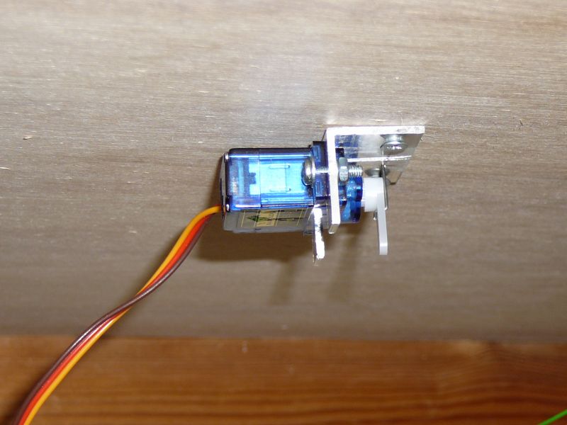
I made all the servo mounts and I must say the U channel is probably fewer cuts and holes, there wasn't any U channel in the local hardware store.
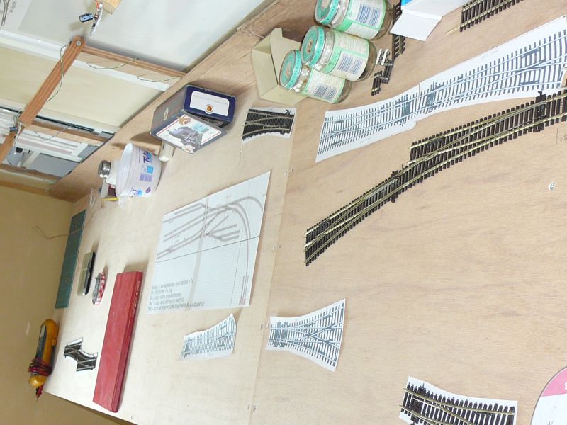
Laid that horrible approach curve yesterday as I have the 1st 3 long points of the approach so things are coming along, servo's fitted and working too. There is some audible noise but not enough to worry about and I guess it only lasts 1/2 second or so.
Roger OO DC Steam
Posted
Full Member
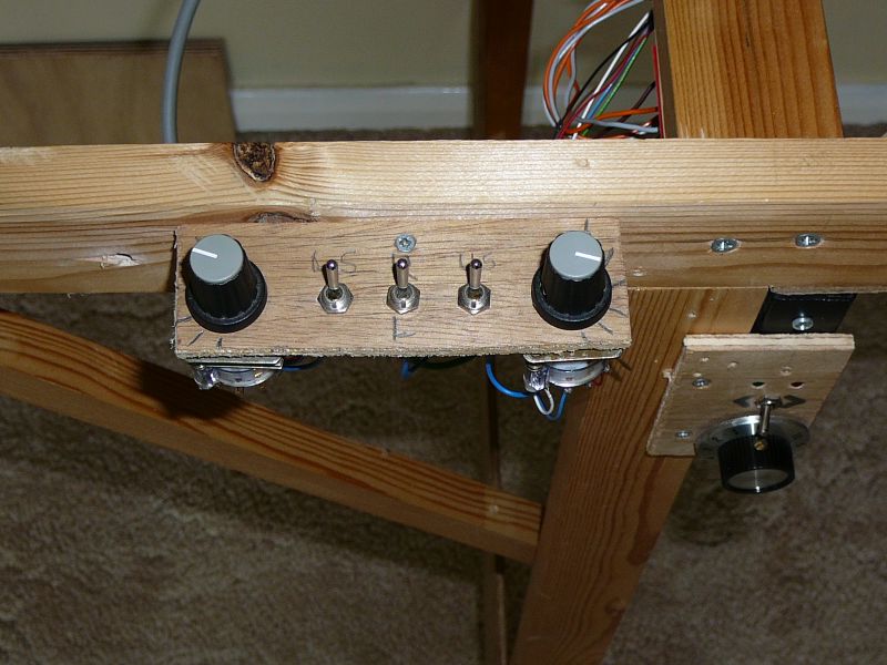
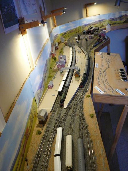
A better view of the traverser minimalist control panel (a feature of this layout is small control panels)
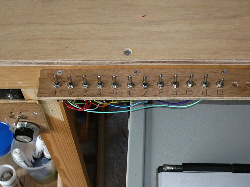
Another minimalist control panel this time for the mainline, passenger platforms & MPD, note the room for expansion. The signal box diagram is traditionally mounted on the wall in front of the operator (signalman).
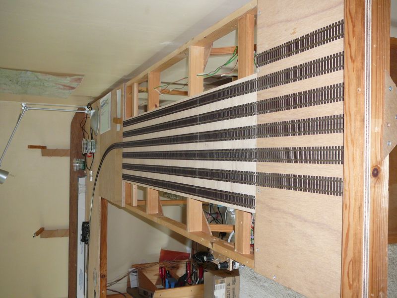
A whole lotta track laying (& aching wiring) to go but stuck for points (Peco pretty please make some).
A point servo with no fiddly microswitches and they are live frogs!
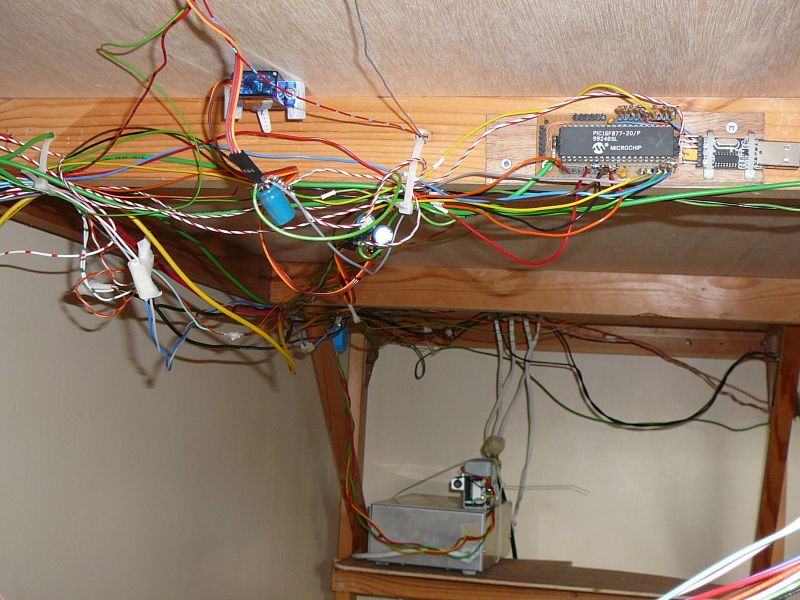
Some peoples wiring seems a bit more artistic than this, usually I have a tidy once it's all in (Hmmm but when is that
 )
)
 Last edit: by fourtytwo
Roger OO DC Steam
Posted

Full Member
Your progress is of great interest as I'm planning to build something very similar so a couple of questions.
- How are you controlling the movement of the plate between settings?
- Given the 4' span might it be worth having a third roller in the middle? From your earlier pic the plate appears to rest on the timber brace which will increase friction or sit above in which case may sag under the weight of stock.
Posted
Full Member
The plate just rests at it's current setting, there are no latches or locks, friction being sufficient.
I considered a 3rd roller but thought it would probably bind due to alignment problems so stuck with two, the extra support as you noticed is provided by subframe members that are liberally polished with "Liberon" furniture wax that I use in another of my hobbies (wood turning), it's a very hard wax and hopefully won't act as a dirt trap. The ends are also supported by a lip of the subframe, this is probably what provides enough friction to stop things moving when you don't want them too yet remains operable one handed.
Just as a complete aside in a limited space had you considered the cartridge system where the "single line plate" is completely removable and stored elsewhere (not on the layout, but perhaps under it) one of many.
Roger OO DC Steam
Posted
Full Member
I tend to "cobble" things up wire-wise until I'm sure it all works, then I tidy things up so it looks rounghly presentable afterwards. I really ought to identify my underboard wires but I've got as far as "red is live, black is return/negative/the other one" and white is for frogs. More colours will arrive once I start with signals, lights and other scenic effects.
'Petermac
Posted
Full Member
Remember the phrase "learning the box" so I am hoping the simple solution will add interest, possibly with bell codes as well at some later time :)
I guess only having to deal with a few wires is attractive though TBH most of what you see under there concerns servo's & frogs in any case! About my only colour codes are green for ground and red/orange/yellow for something nasty enough not to short out (a power supply of some kind). But as a modular layout it has connectors at each board boundary that makes the documentation of the wiring a little easier.
Roger OO DC Steam
Posted
Full Member
Hi Colin thank you for your interest,
The plate just rests at it's current setting, there are no latches or locks, friction being sufficient.
I considered a 3rd roller but thought it would probably bind due to alignment problems so stuck with two, the extra support as you noticed is provided by subframe members that are liberally polished with "Liberon" furniture wax that I use in another of my hobbies (wood turning), it's a very hard wax and hopefully won't act as a dirt trap. The ends are also supported by a lip of the subframe, this is probably what provides enough friction to stop things moving when you don't want them too yet remains operable one handed.
Just as a complete aside in a limited space had you considered the cartridge system where the "single line plate" is completely removable and stored elsewhere (not on the layout, but perhaps under it) one of many.
Hi Roger,
Most helpful guidance as I will be going to a traverser when I do start my new layout, timing ill-defined at present.
My current layout Westown-Heathfield on here is highly challenged in the space department and so I've made a whole range of cassettes from 3 coach / 8 wagon size down to single loco ones. It was reported in Feb last year and easiest seen on pps 13-4 of my gallery rather than by searching pages. I made a double track access point where the goods extension also fits on. Consequently there's a power access point so the cassettes can be powered by connection. It works perfectly well but swapping out is just another task and I don't find myself using as much as I should!
One big advantage is it allows me to do a turntable type loco turn around "in the wings" because I wired the cassettes so they can be put on either way round. Quick disconnect, rotate (with end plates on) and reconnect to track / the second socket then drive off. very quick operation.
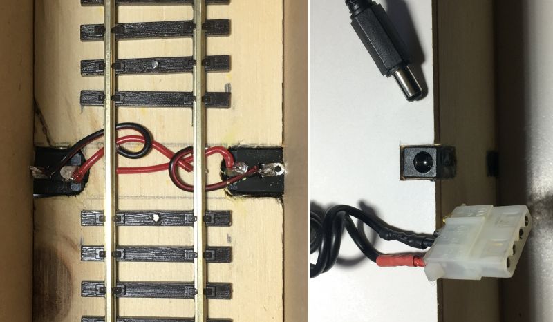
The power link is made by PC DC Power line connector with the Male sockets inset in the ply base of the cassette either side of track at mid point.
Note: The one shown earlier in my pic on Gallery p13 was just a trial run with an audio jack to test the concept.
Colin
Last edit: by Colin W
Posted
Full Member
Roger
Roger OO DC Steam
Posted
Full Member
Catching up on what you've been up to, so please forgive me if I turn back a few pages and comment briefly on the plan and the possible locations for the cattle dock.
Browsing through my fairly large collection of station plans, it seems that close matches to your sketch could have been found at Banbury (Merton Street), Harborne, Llandudno, New Brighton, Oxford (Rewley Road) and Windermere terminii during the grouping. Southport was also similar, but larger (11 platforms), due to the seasonal traffic.
Most of them had the coaling and livestock on opposite sides of the station buildings, unless restrictive natural features constrained the options. In most cases, coaling also took place nearer to the station throat than the movement of goods or chattels.
David.
9C, Hibel Road & Macclesfield Central: 30 May 1941. Various scales
Landscape 1:150, Buildings 1:152·4, 9mm Track 1:159·5, Stock 1:148
Landscape 1:150, Buildings 1:152·4, 9mm Track 1:159·5, Stock 1:148
Posted
Full Member
Thank you so much for those suggestions, I was able to find some (Banbury, Harborne & Oxford) on Dissused stations I have found it very hard to find branch terminus station plans, I have one GWR book but it deals mostly with mainlines and has very few branches in it. You have given me more fodder to think upon, certainly any idea of placing the cattle dock near the passenger station seems a non-starter so I think the run-round loop stub will be a loading dock and or parcels. It could be the smelly cattle are far out on the line into the corner intended for a gasworks or similar in that a few cattle trucks blocking a private siding periodically would not be a problem.
The whole station is a bit one sided an that all the goods are to the back of the baseboard (but well within reach) with the passenger station at the front however the die is now very much cast. This is my first OO layout in some 35 years so it is rather an experiment to get used to the scale all over again, that is one reason it doesn't have a name or specific location other than "Experiment". Another thing that may alter the balance between the passenger station and goods facilities will be the slow acquisition of stock. Due to lack of pointwork (Peco problems) I think it will be a while before the goods side gets laid out but I will certainly have to sort out where the major features are going first :)
Of course I have many RM & CJF plans from over the years but they are someone else's interpretation of a prototype with there particular compromises included hence my thirst for prototype plans. One again many thanks
Roger
Last edit: by fourtytwo
Roger OO DC Steam
Posted

Site staff
( Best to check the spelling if it's me and I'm in a rush through
 )
)Cheers
Matt
Wasnie me, a big boy did it and ran away
"Why did you volunteer ? I didn't Sir, the other three stepped backwards"
"Why did you volunteer ? I didn't Sir, the other three stepped backwards"
Posted
Full Member
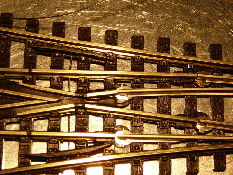
A Peco live frog 3-way turned up yesterday and solved a mystery for me, how up to date were the pictures in the Peco online catalogue and could you infer the connections from them, answers NOT & NO, so here are a couple of pictures of the real article for those similarly wondering
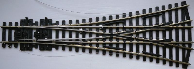
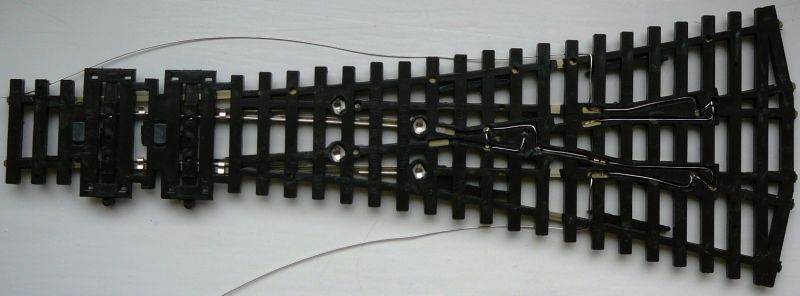
Note the switch rails are entirely isolated and only powered by the contact tabs visible in the sleeper cutouts adjacent to the tiebars. The outer set will be fairly easy to tie to the outer running rails with the sleeper cutouts provided between the two sets of frogs but the inner pair are going to be hard as there is not much metal to absorb the heat during soldering. Notice that two of the frogs are joined, I worked out a switching table for it and that turns out to be ok. Note this is code-100 in a plastic sleeve (not the old cardboard box) and it is possible code-75 is different again!
Last edit: by fourtytwo
Roger OO DC Steam
Posted
Full Member
Good luck with that Roger. I do have a couple of 3-way points on my layout but mercifully, unlike all the "simple" points, they will remain dead frog, at least for the time being ………………
'Petermac
Posted
Full Member
Well this might put you off live frogs or at least joining the switch to the running rails forever :twisted:
I finally plucked up courage, firstly the nice breaks in the sleeper base provided by Peco proved to be useless so new ones were mined with a dental burr

The flux pen is handy to assist tinning the rail underside as is holding down onto in my case an aluminium sheet to try absorb some heat but unfortunately you still need quite a bit from a hot iron to do it.
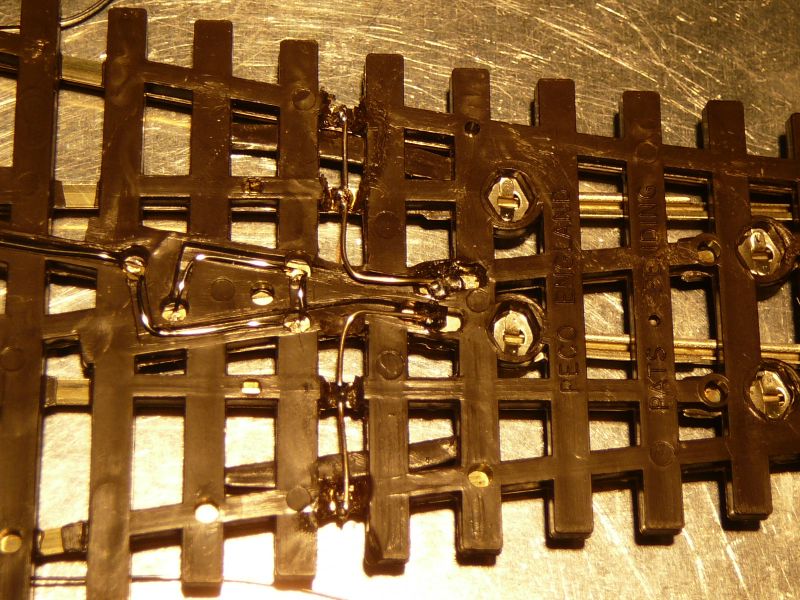
So there is the result after the wires are soldered
Unfortunately you can see the effect on the plastic
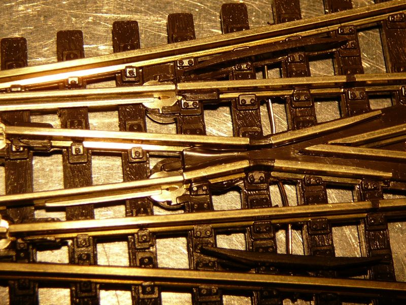
I was very lucky indeed to get away without apparently moving the rail, however I think if I was going to do a lot of this I would make myself a spot-welder like the ones peeps use for tabbing Lithium cells.
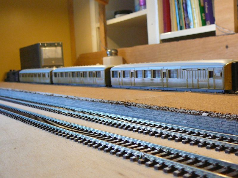
On a lighter note whilst trying to avoid doing the above I stone papered the platform edges and stuck hardboard sheets on the top of the base to form the platform surface. The base is 12mm MDF screwed down to the baseboard whilst the hardboard (3.5mm) is stuck down to the base with a few dabs of hotmelt (beware sets very rapidly).
Roger OO DC Steam
Posted
Full Member
I do have 2. maybe 3, three-way points but they're dead frog - Code 100.
Regarding the hot melt glue, it does set very quickly and therefore, in my experience, gives a fairly brittle joint because the glue doesn't have time to penetrate the materials - the bond seems to be just a physical bond to what texture there is in the materials. It's certainly handy but only for totally static bits.
'Petermac
Posted
Full Member
Here's a print from AnyRail 6.37.0 showing a slightly simplified plan of Windermere station during the mid-1930s.
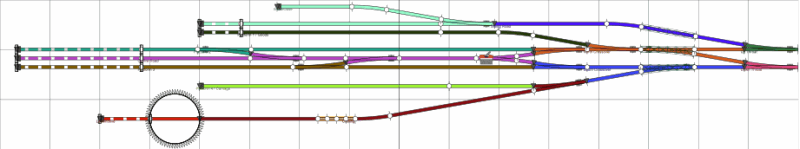
From the bottom (SW) of the plan, which is now covered by Booths' car park, towards the <omitted> merchant's yard beyond the top (NE) are the following identifiable features:
The locomotive facilities (72 foot shed partially embedded into the station buildings, 48' turntable about 12' from the shed {AnyRail only has the Ransome & Rapier 70' version in its library}, coaling, water and ashpit).
<siding between loco road and platform 4 omitted>
Platform 4, 495' in length but with the line terminating 40' short of the station buildings (space to handle one large tank locomotive and seven carriages on arrival, eight carriages on departure), fully open.
Platform 3, 675' in length (space to handle one large express locomotive and ten carriages on arrival, eleven carriages on departure), covered by the overall canopy for 180' with the remaining 495' fully open.
Run around and layover road, covered for 180'.
Platform 2, 675' in length (space to handle one large express locomotive and ten carriages on arrival, eleven carriages on departure), covered by the overall canopy for 180' and by a lower canopy cantilevered from the goods and parcel warehouse for 140' with the remaining 355' fully open.
Platform 1, 355' in length (space to handle one large tank locomotive and five carriages on arrival, six carriages on departure), fully open. The attached plan shows an extra 60' (one carriage) length on this platform, covered by the lower canopy seen above platform 2.
Goods handling facilities, 340' in length, covered for 60'.
<goods bay siding omitted>
Cattle dock on other side of peninsula from main goods siding and bay, 300' in length, fully open.
<omitted merchant's yard containing four sidings individually leaving the goods road along the purple section>
The coloured sectioning is overlaid to illustrate possible divisions for the analogue operation of a model.
=-=-=-=-=-=-=-=-=
I hope that gives you a few more ideas about ways to lay out your platforms, loco handling, inert goods and livestock.
David.
Last edit: by 6243
9C, Hibel Road & Macclesfield Central: 30 May 1941. Various scales
Landscape 1:150, Buildings 1:152·4, 9mm Track 1:159·5, Stock 1:148
Landscape 1:150, Buildings 1:152·4, 9mm Track 1:159·5, Stock 1:148
Posted
Full Member
The problem is the switch rails are only energised by the tiny metal tab underneath making contact with either the adjacent switch or running rail in an impossible to clean location that is liable to get glue on it during ballasting, personally to me that's just not reliable enough (I have had my time with dodgy point blade contacts) hence the additional wire links.
I was a bit caught by surprise at the setting speed of the hotmelt in that situation but if I used my favourite alternative UHU I would have had to find weights to hold the hardboard down while it set as unfortunately the hardboard was a bit warped. I like the texture of the hardboard surface but the edges look terrible so I just might have to replace them with plywood however often thin ply is only 3 ply with the only decent veneer on the outside leaving some rough old stuff that almost looks like cork as the filler so I may be no better off, will have to take a close look next time I am in a hardware store as I don't have any to hand.
Hi David,
Thank you so much for the plan and the very good text description, that must have taken you ages and I am very grateful indeed. I do not have the pointwork (ongoing Peco shortages) presently to do the goods side of the station so other than deciding what the run-round loop spur is for (I think loading bay & parcels) I have plenty of time to think. For some reason or another although I have a whole bookshelf of railway related books very few of them have prototype track plans in them and of course once you become more selective (like medium branch terminus) the availability becomes even rarer so I am very grateful indeed to those blessed with such information in helping me, thank you again :)
Of course I realise this morning whilst beginning the track layout of the MPD it is way oversized for the station but then I think modellers often end up with more stock of one kind or another that will fit on the layout so it may be handy in the future.
Regards
Roger
Last edit: by fourtytwo
Roger OO DC Steam
Posted
Full Member
Roger,……………… You have given me more fodder to think upon, certainly any idea of placing the cattle dock near the passenger station seems a non-starter so I think the run-round loop stub will be a loading dock and or parcels. It could be the smelly cattle are far out on the line into the corner intended for a gasworks or similar in that a few cattle trucks blocking a private siding periodically would not be a problem.
…………………….
The quintessential (have I got that right?) GWR branch terminus of Ashburton, much modelled, had its cattle pens on the stub of the run round loop, directly opposite the platform. And looking at Middleton-in-Teesdale, the cattle pens here were very close to the station building.
Last edit: by spurno
Alan
Posted
Full Member
Roger,Hi David,
Thank you so much for the plan and the very good text description, that must have taken you ages and I am very grateful indeed. I do not have the pointwork (ongoing Peco shortages) presently to do the goods side of the station so other than deciding what the run-round loop spur is for (I think loading bay & parcels) I have plenty of time to think. For some reason or another although I have a whole bookshelf of railway related books very few of them have prototype track plans in them and of course once you become more selective (like medium branch terminus) the availability becomes even rarer so I am very grateful indeed to those blessed with such information in helping me, thank you again :)
Of course I realise this morning whilst beginning the track layout of the MPD it is way oversized for the station but then I think modellers often end up with more stock of one kind or another that will fit on the layout so it may be handy in the future.
Regards
Roger
It didn't take *that* long and it was my pleasure to give you an example based on the operating practices of the largest grouping company (over 36% of all railway infrastructure and movements), rather than the smallest (less than 14%) as usually seems to be the peculiar case in this hobby. One other thing that a second look at my maps and plans reveals is that (site permitting) the cattle pens were usually east or north of the station buildings…. downwind in the UK's prevailing southwesterlies.
You're quite right about our stock collections, they are often those of the secondary MPDs rather than the tertiary ones which would be found alongside our stations. I do doubt that many, apart from Messrs Stewart or Waterman, would have the complement of a primary depôt such as Crewe North or Longsight.
:mrgreen:
9C, Hibel Road & Macclesfield Central: 30 May 1941. Various scales
Landscape 1:150, Buildings 1:152·4, 9mm Track 1:159·5, Stock 1:148
Landscape 1:150, Buildings 1:152·4, 9mm Track 1:159·5, Stock 1:148
1 guest and 0 members have just viewed this.