Waddlemarsh
Posted
Full Member
Somewhere SW of London. Somewhen before today
Wow look at the transformation! It’s starting to look great.Most photos for me too go the wrong way from my phone, I have to put them in the computer first.

Posted

Full Member
Meanwhile the layout proceeds very slowly along and I have now to understand the wiring requirements for a piece of specially-built pointwork. This is a scissors crossover but with one of the four points being a double-slip diamond. It allows two tracks to feed three sidings with entry and exit available in any direction. Once that is working and pinned down the layout should be fully wired and working as regards traction current. The third rail for the passenger line will be a dummy; I have conducted trials aimed at having it live and used for traction feed but our various manufacturer's tolerances and scaling mean that the pick-up shoes are in entirely different positions across the brands. For a couple of metres of visible running line that was going to be too much effort for too little gain and the "live" rail will not be live.
Posted

Full Member
If you need any advice with your wiring Rick, just ask me ………………………. :???: :???: :???: :cheers

'Petermac
Posted
Full Member
SWMBO is unwell and is due into hospital on Monday. This gives me a little time at home while she is recovering to both be close to her and deal with matters outstanding on the model without too much interruption. I have taken next week off work so hopefully will be able to make some progress.
Posted
Full Member
SWMBO has been home recovering from her surgery for a few days now and is doing well. She still has at least two more weeks off work.
The layout is not recovering and lurches from short circuit to short circuit. In fixing the latest one I managed to cause more damage which means I now need to replace a yard of plain and ballasted track in addition to re-fettling the offending Y-point.
I am going to have to get a diagram drawn because if I can't figure out what needs to be don I shall either tear out my remaining hair or tear up the track and try flower arranging instead.
Over two years and the only progress made has been to move shorts from one place to another …….
Posted

Full Member
Flower aranging is over-rated
Let us have a diagram and where the problems appear to be and the combined Brains of YMRC will see you right!!
Barry
Shed dweller, Softie Southerner and Meglomaniac
Posted
Full Member
Would it be easier to just have a plain track diagram without showing where the feeds etc are and allow folk to fill in the blanks, as it were?
Posted

Full Member
I would find a track diagram showing the existing feeds helpful and in addition the existing location of all IRJs (insulated rail joiners) is essential.A diagram will be sorted.
Would it be easier to just have a plain track diagram without showing where the feeds etc are and allow folk to fill in the blanks, as it were?
I am sure it will all be resolved Rick
Best wishes
John
Posted
Full Member
Posted
Full Member
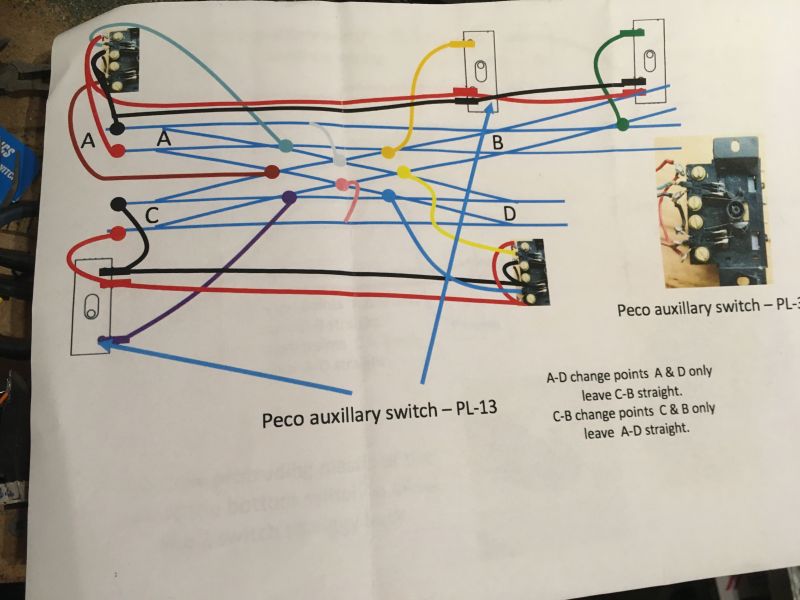
The colours used on the wiring diagram are as fitted to the track piece and all those which exist are fitted exactly as shown. However there are "doubled" or "piggy-backed" auxiliary switches (Peco PL-13 as per diagram) which is something I cannot get to work. They simply will not piggy-back with each other. The bar from the point motor is not long enough to go through two and where I have got them doubled up they jam the motor.
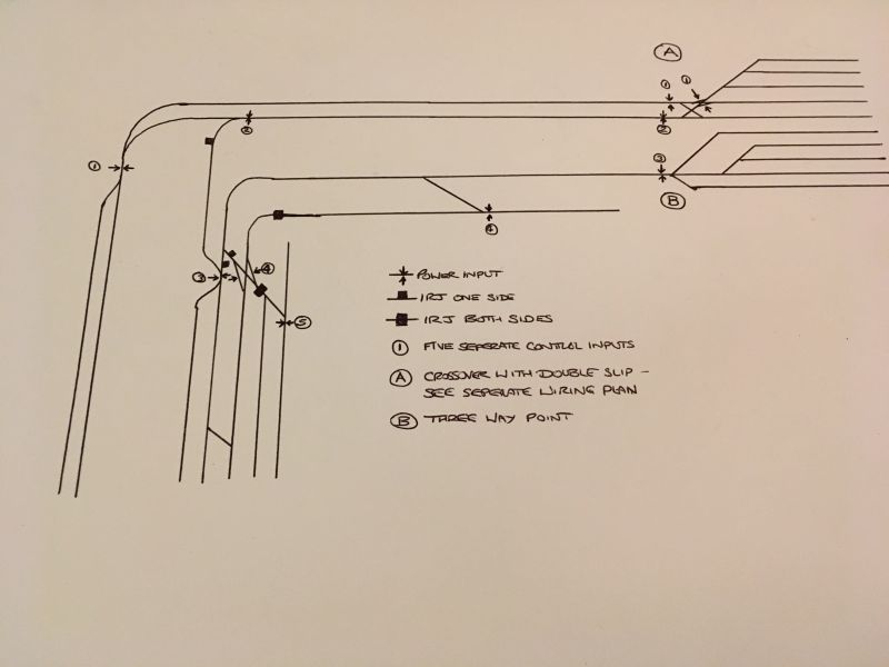
At the bottom is the actual track plan with the position (as of today) where I have power inputs and IRJs. Clearly there is something not right because while individually most parts of the layout will work under power there remain dead sections through several points and both double-slips, plus there are numerous shorts which I don't understand enough about to rectify.
All points are Peco code 75 electrofrog and all are fitted with PL-13 accessory switches except for the three-way which has nothing fitted, and neither do the points in the fiddle yard which lead to dead ends because frog switching here is not required.
Good luck!

Posted
Full Member
Could I suggest that we take this in stages taking one section of simple trackwork at a time and leave the 3 way and diamonds until the basic areas are sorted.
Taking this approach lets focus right now solely on the twin sidings and tracks leading up to the fiddle yard A at power feed 1
There are two points back to back from this single power feed…..It would be helpful if you numbered the points but for now lets call them A1 (top) and A2 (bottom)
[1] A1 must be isolated on the ends (toes?) …..as shown there will be a short whichever way this point is thrown.
I assume A1 has switched polarity? Check that this now works correctly
I assume A2 is not switched and relies on the turnout blade to power the frog ?
Personally I think I would have isolated the two points and added another power feed
[2] Isolate all four ends of the diamond/double slip (?) leading to the fiddle yard A……we will add a separate power supply for this later
[3] Sidings SA1 thru SA4 are now powered and should work without issue…..confirm
[4] Add a power feed to the bottom siding SA 5
[5] Check trains will run from each siding on both routes up to the diamond.
When you are absolutely satisfied this all works we can address the diamond or double slip
Hope this helps……Nec aspera terrent ……my old army motto "Difficulties be damned"
John
Posted

Site staff
Untitled Page
it has basic frog wiring for normal turnouts, slips & scissors crossovers.
I personally would not use 2 PL13's ganged but a PL15 twin microswitch
Ron
NCE DCC ; 00 scale UK outline.
NCE DCC ; 00 scale UK outline.
Posted

Full Member
Did you want a double slip in the middle with a branch to the upper right, or a crossover (diamond) in the middle and a slip upper right? The examples I have seen are the latter. Crossover wiring is simple, basically continuity and isolation, that would have left the slip, which is straightforward. These assemblies are made from Peco offerings, so no real track building, just cut and shut. Or was this a custom build?
Nigel
©Nigel C. Phillips
Posted
Full Member
Sol I already have that page saved and have read it couple of times. I also have Ian Morton's book Aspects of Modelling - Electrics which is a good guide but of course cannot cover every scenario.
John I shall try to follow your thoughts when I have an hour or two to spare at the layout.
Posted
Full Member
So the slip is at B (which would correspond to the photos of this arrangement on the web and eBay). Missed that on the diagram :oops:. 3 long points, 1 crossover, 1 double slip. I noticed you have live frogs in the diamond. Life is a lot simpler if they are insuls or dead metal.
I would contact Mr. Nicholls to see what is wrong.
Nigel
©Nigel C. Phillips
Posted
Full Member
Posted
Full Member
An 0-6-0 will usually trundle across insulfrogs or for that matter a dead metal frog as long as the frog is shorter than the wheelbase. The insulfrog design is different to the electrofrog - around 2-3 sleepers for the insulfrog, around 7 for a large radius electrofrog. Can you get insulfrogs in code 75?
If you are rebuilding it's worthwhile shortening the distance between the closure rail and the frog.
Nigel
©Nigel C. Phillips
Posted
Full Member
I have used insul Code 75 crossings and they work fine without any hesitation with 6-coupled tank engines. I don't have any 4-coupld so cannot comment.
Barry
Shed dweller, Softie Southerner and Meglomaniac
Posted
Full Member
Posted
Full Member
I now have a couple of PL15s How should I wire them up in this context please?Rick, I know you are a DC man so can I suggest you read this page for starters
https://brian-lambert.co.uk/Electrical_Page_3.html
it has basic frog wiring for normal turnouts, slips & scissors crossovers.
I personally would not use 2 PL13's ganged but a PL15 twin microswitch
1 guest and 1 member have just viewed this: peterm.