Waddlemarsh
Posted

Full Member
Somewhere SW of London. Somewhen before today
I agree with Marty, you have done a great job with what appeared to be a very awkward bit of scenery. Having made the same footbridge, I am very impressed at your kit bashing tooMichael

Posted

Full Member
Further furtling has taken place.
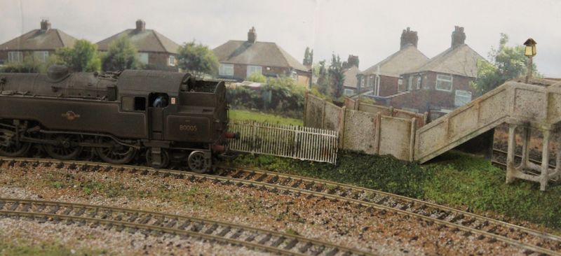
The detailing along the line of the backscene has had its greenery built up to conceal the slight gaps and bits of white paper. The concrete fence panels have been weathered and stuck in place and the footbridge has also been fixed down. The points of contact are tiny and I'm not too sure I can trust the gluing at this stage but time will tell.
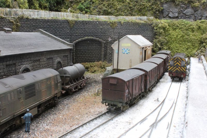
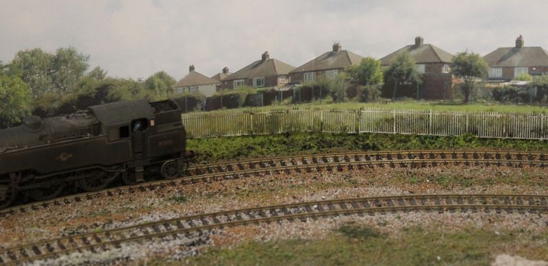
The grass behind the houses has now been fenced off from the railway. Keen eyes will observe that I have used GWR spear fencing rather than an SR style. It might not be the final version but it will certainly do for now. Very keen eyes may spot that the weathered white fencing used has been recycled from Penhayle Bay where it sat alongside the main line above the loco shed and yard; from the top image to the lower ones by the magic of modelling.

Posted
Full Member
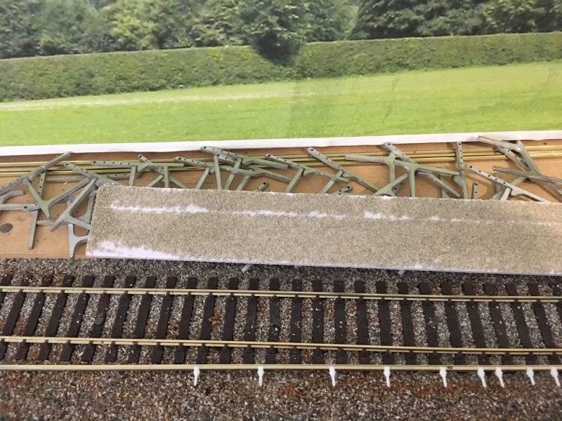
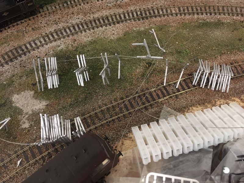
Dart Castings SR platform supports and fence posts. Peco conductor rail insulators going onto code 60 rail. And a closer view of the castings - sorry it lost definition - showing the reason I have been boring holes recently. 4x0.5mm and 1x1.0mm per post to drill out, 100 off. So 500 tiny holes plus those required to locate the "pots" into the sleepers …..
3mm foam board covered in fine sand to create the concrete-slab platform of the halt.
I am awaiting a delivery of piano wire for the fence wires and will attempt to get the castings looking like concrete after that is threaded through.
Posted

Full Member
I saw your post on FB and thought you were drilling plastic sprue - didn't realise you'd invested heavily in metalwork. :roll:
What's it like to drill - i.e. does it clog the drill fairly quickly ?
'Petermac
Posted
Full Member
It has been a remarkably boring couple of weeks! Doing a few now and again - including just before bed most nights - results in the job getting done without my patience being exhausted.Well it looks as if you've had a boring week Rick !!
I saw your post on FB and thought you were drilling plastic sprue - didn't realise you'd invested heavily in metalwork. :roll:
What's it like to drill - i.e. does it clog the drill fairly quickly ?
I will admit to being on my second 0.5mm bit now and am honestly surprised I haven't destroyed more. They are the finest thing I have yet worked with, size wise.
The casting is quite soft so easy to drill with the tiny amount of swarf just tapped off at the end of each bore. The more difficult part is maintaining even but light pressure and having the pin-vice perfectly vertical with respect to the job. Each bore can be done in one operation without a need to clean the drill part-way through.
This is the half-way point. 50 down, 50 to do. An extra pack is on its way from Dart Castings to boost the numbers as I am a few short and there have been a couple of breakages. More posts have been terminally damaged than drills so far - by a factor of three to one.
 Last edit: by Gwiwer
Posted
Full Member
Posted
Full Member
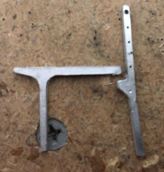
The castings are designed to butt-fit rather than having one overlap the other as I am doing. Ideally they would be soldered but I don't have the facilities to low-melt solder so many parts. As much the absence of a suitable workspace as the out-of-stock low-melt solder.
So I am super-gluing the two parts together with the overlap as shown. It isn't quite right but the joins won't show and any irregularities in leg length can be trimmed. The legs will need trimming anyway because as supplied and once fitted with the foamboard sheets they result in a slightly-too-high platform surface. So no more work is involved there than was anticipated.
There are two related and significant pieces of work to do before the platform can be completed. I really must fix the short-circuit through the crossover at the yard end - which is hopefully the last of the electrical problems to attend to - and when that is done I need to trim some woodwork in order to have the tracks running straight through the platform area. Currently there is a curve at one end caused by the fit of point motors at the crossover. It is those motors which require wood to be cut back before the track is firmly pinned in place and the halt is built.
It feels like a snail with a zimmer frame would make faster progress. But progress is being made.
Posted
Full Member
I wonder, why are you using wire for the fence Rick - wouldn't it have been pailings of some kind ?
'Petermac
Posted
Full Member
Seen here at a location typical of the one being modelled the lower four* strands are twisted wire for which I shall use 0.4mm piano wire. The top rail is steel tube. I have 0.9mm piano wire coming but would prefer to use brass rod.
Due to the current circumstances I cannot source fine gauge brass rod but may use it instead of wire at a later date.
This image also shows the prototype of the concrete posts and supports I am currently working on.
Public domain image sourced via Google. Creative Commons licence
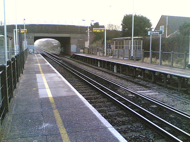
* On closer inspection I only see three strands of wire on this station. I would be happy using just three on mine because it represents 25% less threading of piano wire through tiny holes. And 25% fewer holes to bore out on the other half of the job!
Last edit: by Gwiwer
Posted

Legacy Member
Brian
Last edit: by Briperran
OO gauge DCC ECOS Itrain 4 computer control system
Posted
Full Member
'Petermac
Posted
Full Member
Posted
Legacy Member
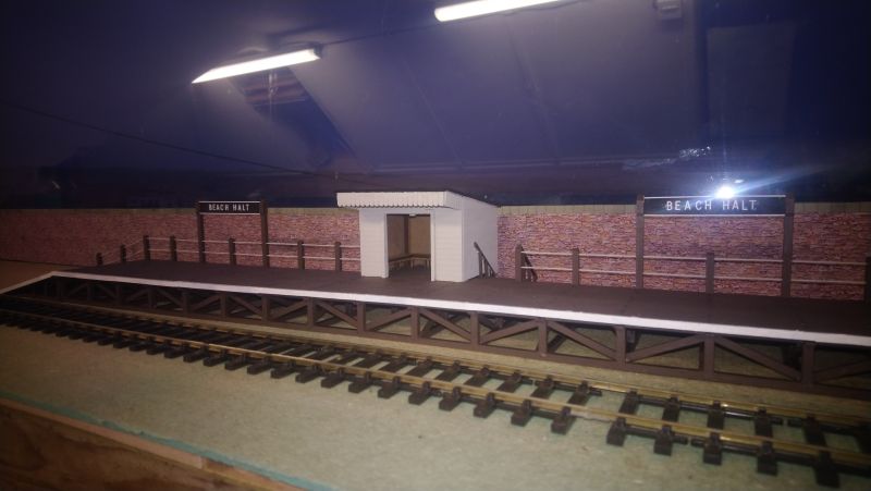
You live and learn - I didn't know they used that kind of fencing on stations Rick - but then, I tend not to study "modern" !! Also, I note Brian has similar fencing on his halt - I hadn't noticed that either - have you posted that photo before Brian ?
Not here Peter but you would have seen it on MRC
Brian
OO gauge DCC ECOS Itrain 4 computer control system
Posted
Full Member
It depends on your definition of “modern†I suppose. Those concrete halts with wire fences were a feature of the Southern Railway from the 1920s onwards. Many were built as lines were electrified or were rebuilds of earlier wooden halts at that time so date from the 1930s.
Ah yes, "Southern" - I'd forgotten - that explains it all …………………..

'Petermac
Posted
Full Member
Either I hadn't noticed it there Brian or it hadn't registered ………….. :thud[user=6]Petermac[/user] wrote:You live and learn - I didn't know they used that kind of fencing on stations Rick - but then, I tend not to study "modern" !! Also, I note Brian has similar fencing on his halt - I hadn't noticed that either - have you posted that photo before Brian ?
Not here Peter but you would have seen it on MRC
Brian
'Petermac
Posted
Full Member
[user=1753]Gwiwer[/user] wrote:It depends on your definition of “modern†I suppose. Those concrete halts with wire fences were a feature of the Southern Railway from the 1920s onwards. Many were built as lines were electrified or were rebuilds of earlier wooden halts at that time so date from the 1930s.
Ah yes, "Southern" - I'd forgotten - that explains it all …………………..

Posted
Full Member
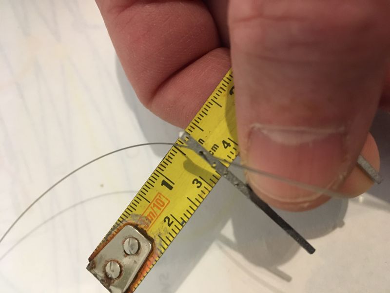
0.4mm piano wire is threaded through 0.5mm holes in the fence posts and will ultimately be weathered down. 50 posts per platform (maybe give or take a few) and four strands of wire per post. That's a lot of threading. Lots and lots ………
The top-most hole is 1.0mm and will have - hopefully - brass rod through it both for stiffness and because the top run on the prototype is steel tube not wire.
Posted
Full Member
What's the translucent choc block shaped thing in front of the locomotive in the photo ?
'Petermac
Posted
Full Member
Last edit: by Gwiwer
Posted
Full Member
The problem with storage space is finding what's in there !! My storage space is full - people tell me I'm a hoarder - but I still often buy new because I can't find the old !!!
Those plug-in choc blocks are great, provided you don't plug and un-plug too often. I've found they can become loose in time.
'Petermac
1 guest and 0 members have just viewed this.